In this section we list the activities to be solved in the following table:
| Checklist | Estatus |
|---|---|
| Linked to the group assignment page | finished |
| Explained how you parametrically designed your files | finished |
| Documented how you made your press-fit kit | finished |
| Documented how you made your vinyl cutting | finished |
| Included your original desing files | finished |
| Included your original hero shots | finished |
Characterize your lasercutter's focus, power, speed, rate, kerf, and joint clearance. Document your work to the group work page and reflect on your individual page what you learned.
Design, lasercut, and document a parametric press-fit construction kit, which can be assembled in multiple ways. Account for the lasercutter kerf cut something on the vinylcutter
This work was carried out by the team made up of teachers from the I.E.S. “FEDERAL REPUBLIC OF GERMANY”, which is detailed below:
Ing. Olenka Odar Jiménez
Ing. Deisy Olguín García
Ing. Roger Zavaleta Lozano
Ing. Luis Montalvo
Técnico Ronald Villar Gonzales
We still do not have a Fab Lab implemented in our institute, so we looked for places where we could carry out our assignments; Although we were limited in the time we could use the machines, we were able to carry out the activity.
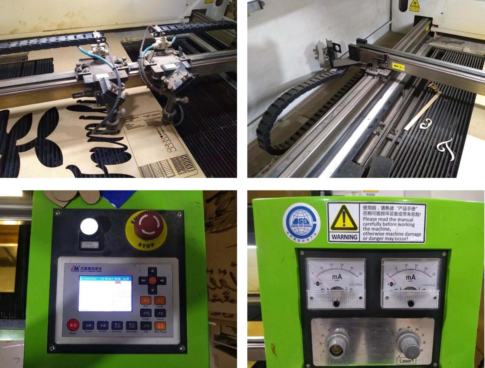
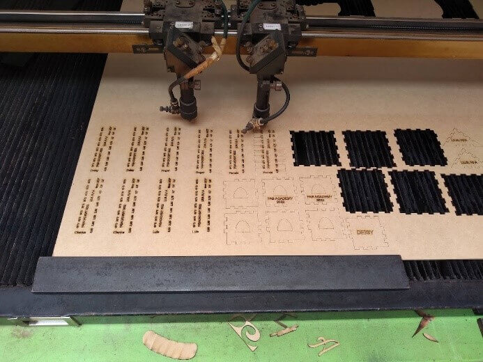
Laser Cutting Engraving Machine CMA 1610 TA, has 2 Tube Laser with power 1 Tube 80 watts. 1 Tube for 1 Head. Can be used 2 Tubes for 2 Head at a time, can also 1 Tube 1 Head is On.

Mark: Hans Yue Ming
Model: CMA 1610 TA
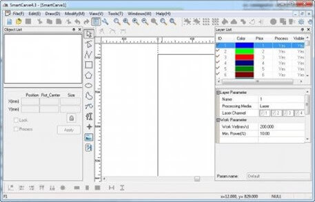
Software: Corel Drawn + SmartCarve4.3
Technical Parameter
 Some photos of the machine that was worked on:
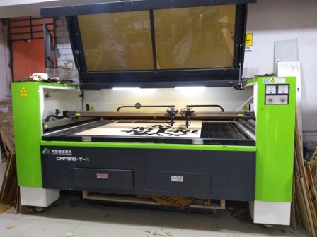
The company Cero 5 S.A.C. belonging to Mrs. Judy Fuentes Silva, located on the corner of Lora y Lora avenue with Elmer Faucett street, rented us part of its facilities for hours to carry out the work in MDF and acrylic using a laser cutter.
In this company, COREL DRAW is used as the base software to design the objects and then these files are opened in the software of the laser cutting machine, which is SmartCarve 4.3; from where the printing order is finally given, not without first indicating the origin of the laser on the same cutter.
SmartCarve4 possesses many functions, such as computer aided design, computer intelligence control, images processing,multi languages, and can deal with various data types, multiple laser processing, multiple layers designs.
It is an epistasy platform software developed by GD Hans Yueming Laser Co., ltd., supporting the processing control and data generation of most laser processing equipments.

Our instructor recommended that we work on the template for our work in Autocad and then import it into Inkscape, but doing so made the letters warp; so he told us to make the letters in Inkscape and the graphics in Autocad, but the process was difficult because the Inkscape files could not be opened in Autocad.
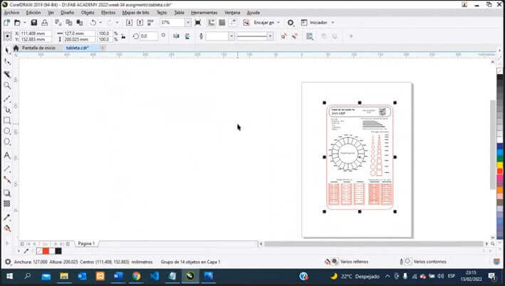
On the other hand, in the place where we would make the laser cut, it works with Corel Draw, so we would correct to make the template and the rulers directly in that software that also allows us to make measurements on the objects using the COTA tool.
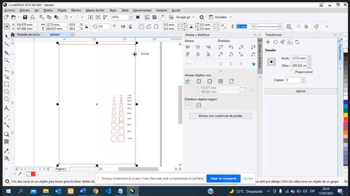

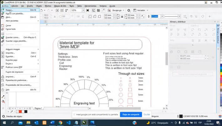
The values test template was made in 3mm MDF, taking into account the parameters:
For the cut: Power = 35%; Speed = 14mm/s
For engraving: Power = 20%; Speed = 40mm/s
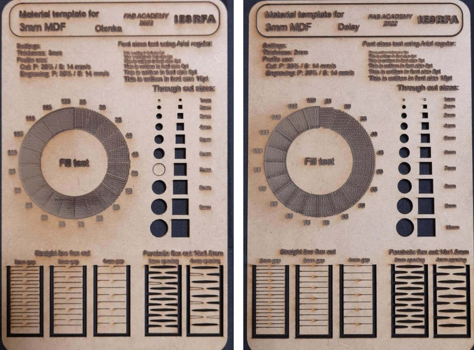
In order for shades of color to be seen in the MDF, the FILL is used, which means the number of lines.
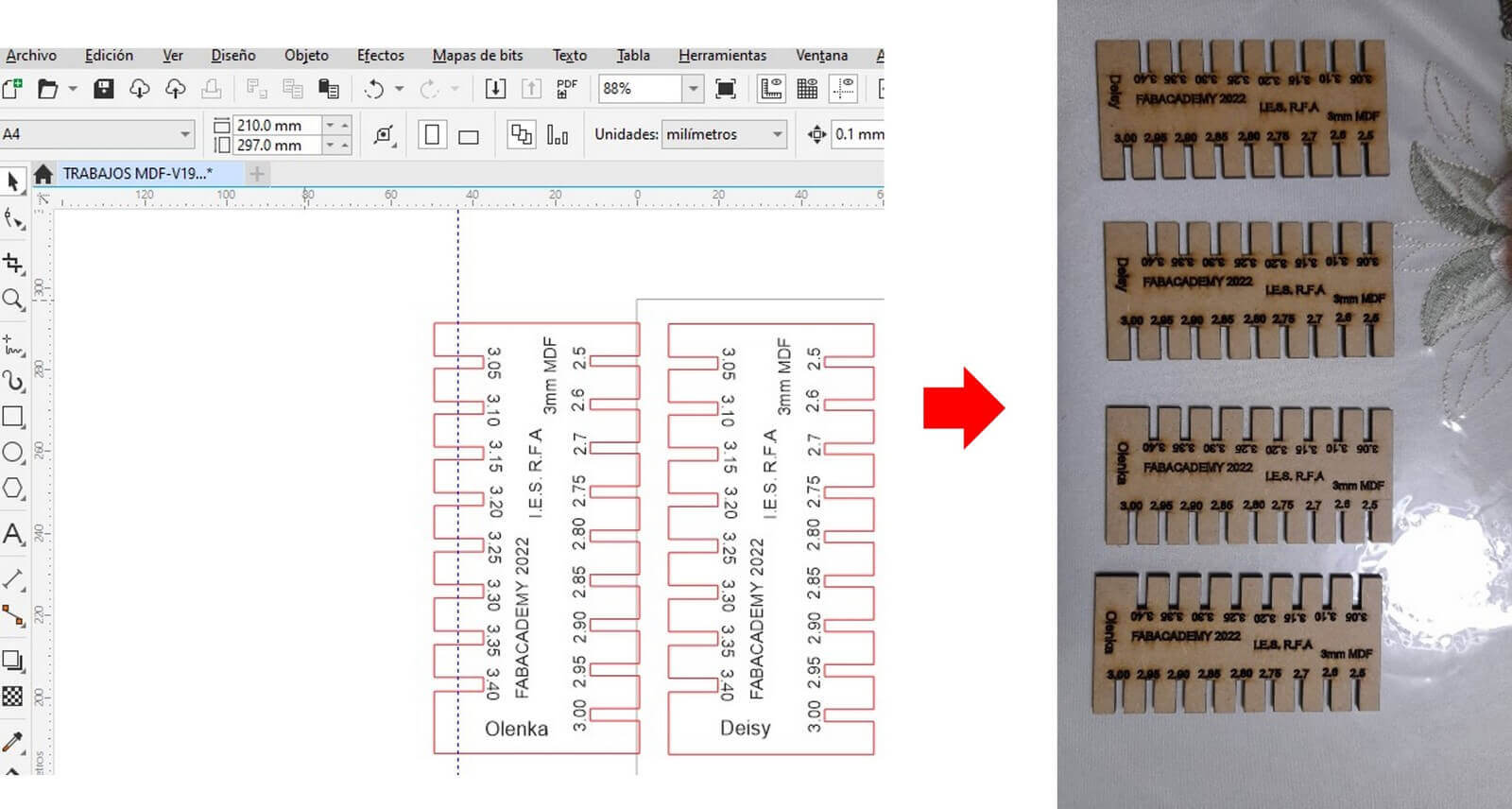
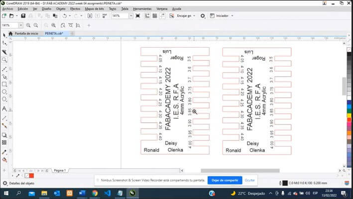
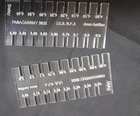
The combs to verify the adjustment of the cuts were worked in 3mm MDF and 4mm acrylic, taking into account that the power is greater and the speed is lower:

Parametric design allows you to create parts whose dimensions can be easily changed, but to do so it is necessary to follow a series of rules so as not to distort the dimensions and shape of the design.
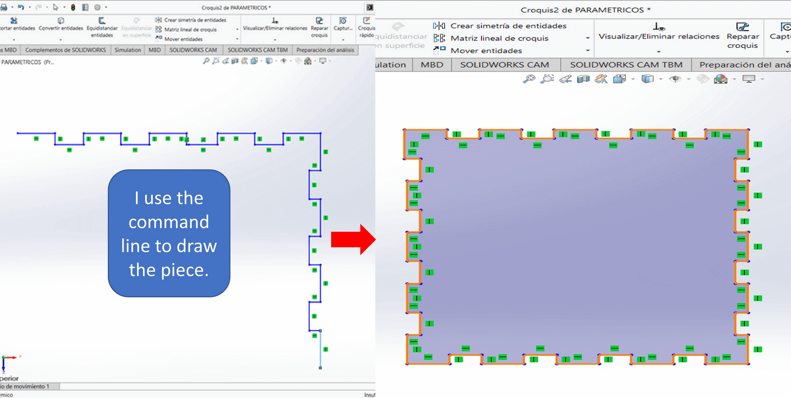
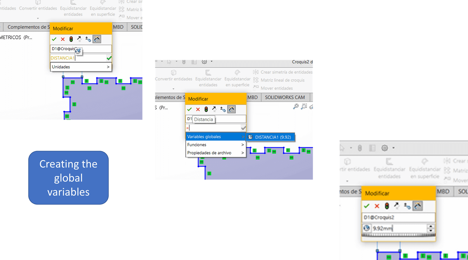
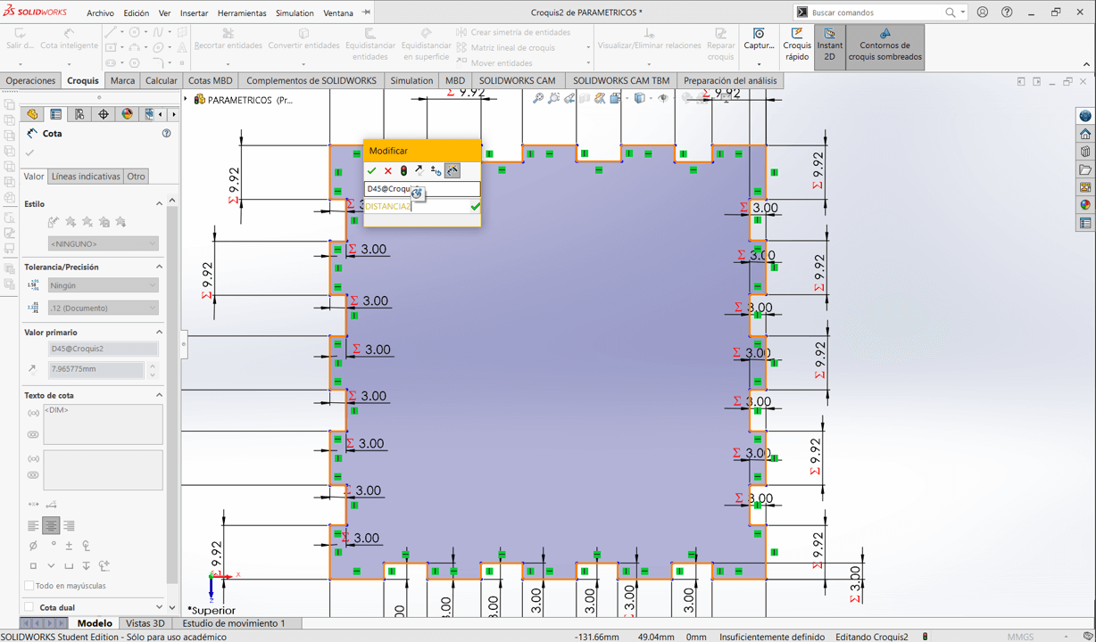
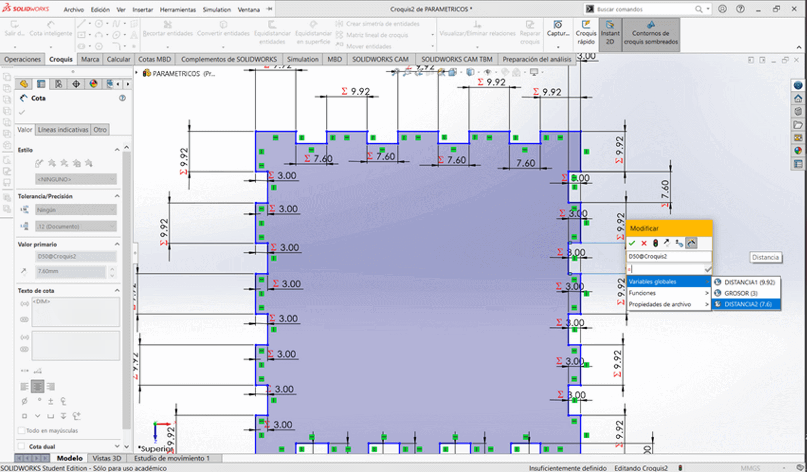
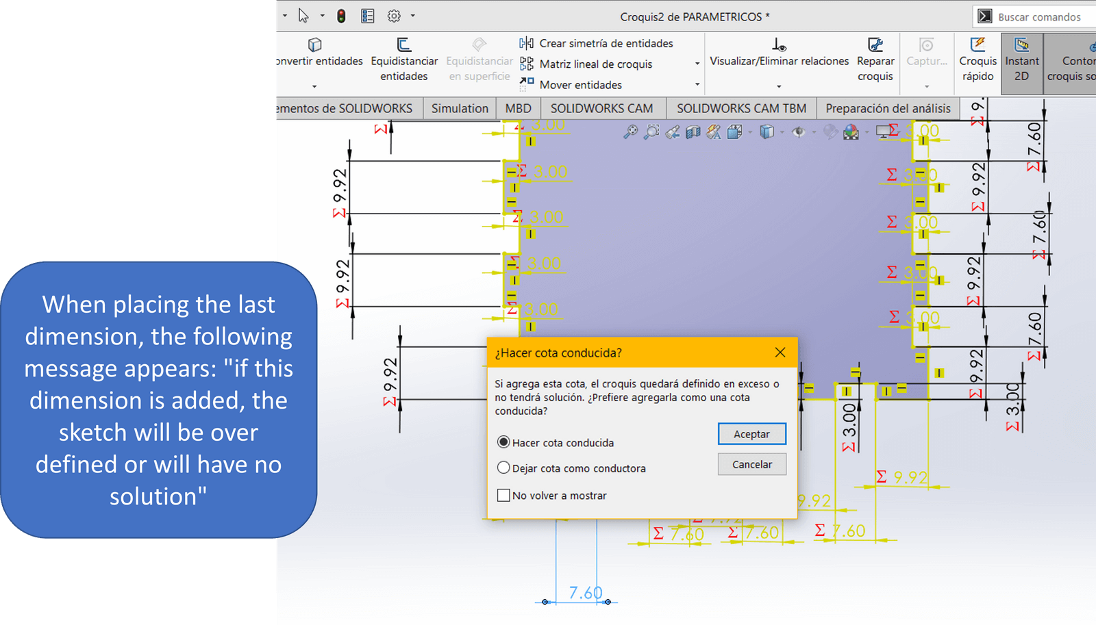
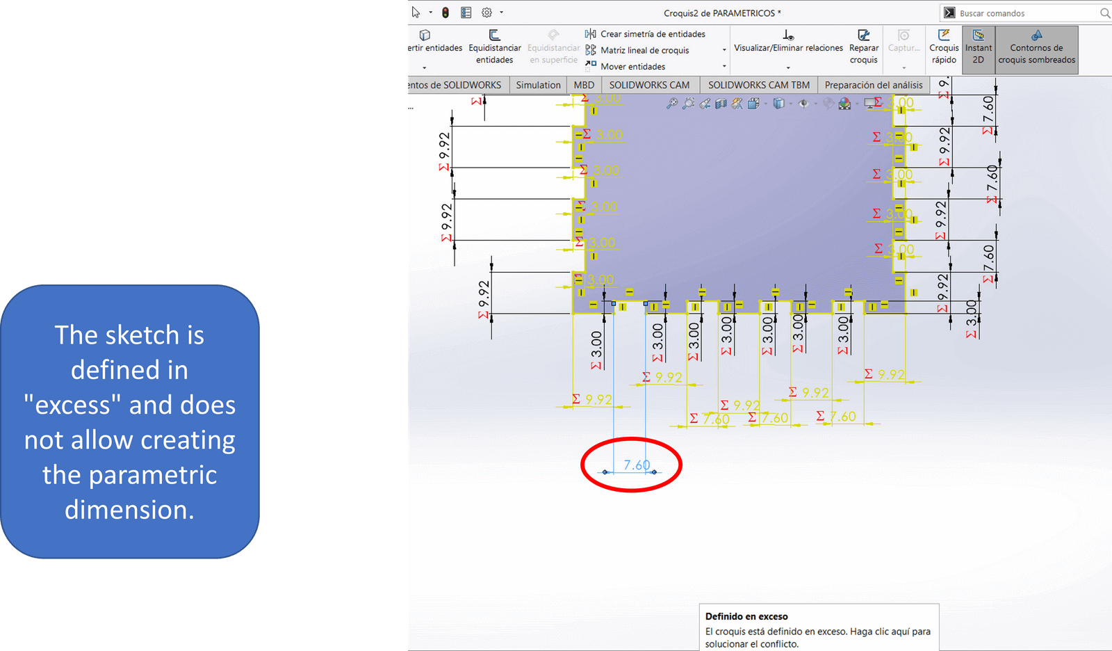
Watching some videos on YouTube, I decided to do the parametric design with Solidworks. With the line command I start to design one of the faces of my press-fit box. Finished my piece, I create the respective "global variables" for this I select "intelligent dimension" and proceeded to create the respective global variables for the different distances that my piece presents. But when I'm almost done, I can't associate a distance with its respective global variable and the sketch is over defined. In such a way that I cannot vary that distance. So he chose to use other software.
I leave here the file that I worked on in Solidworks.
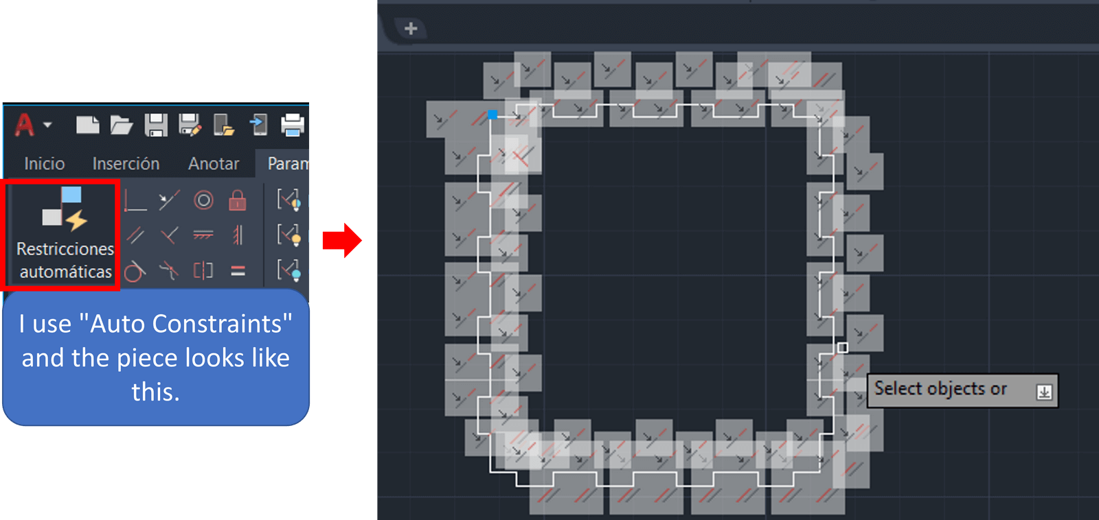
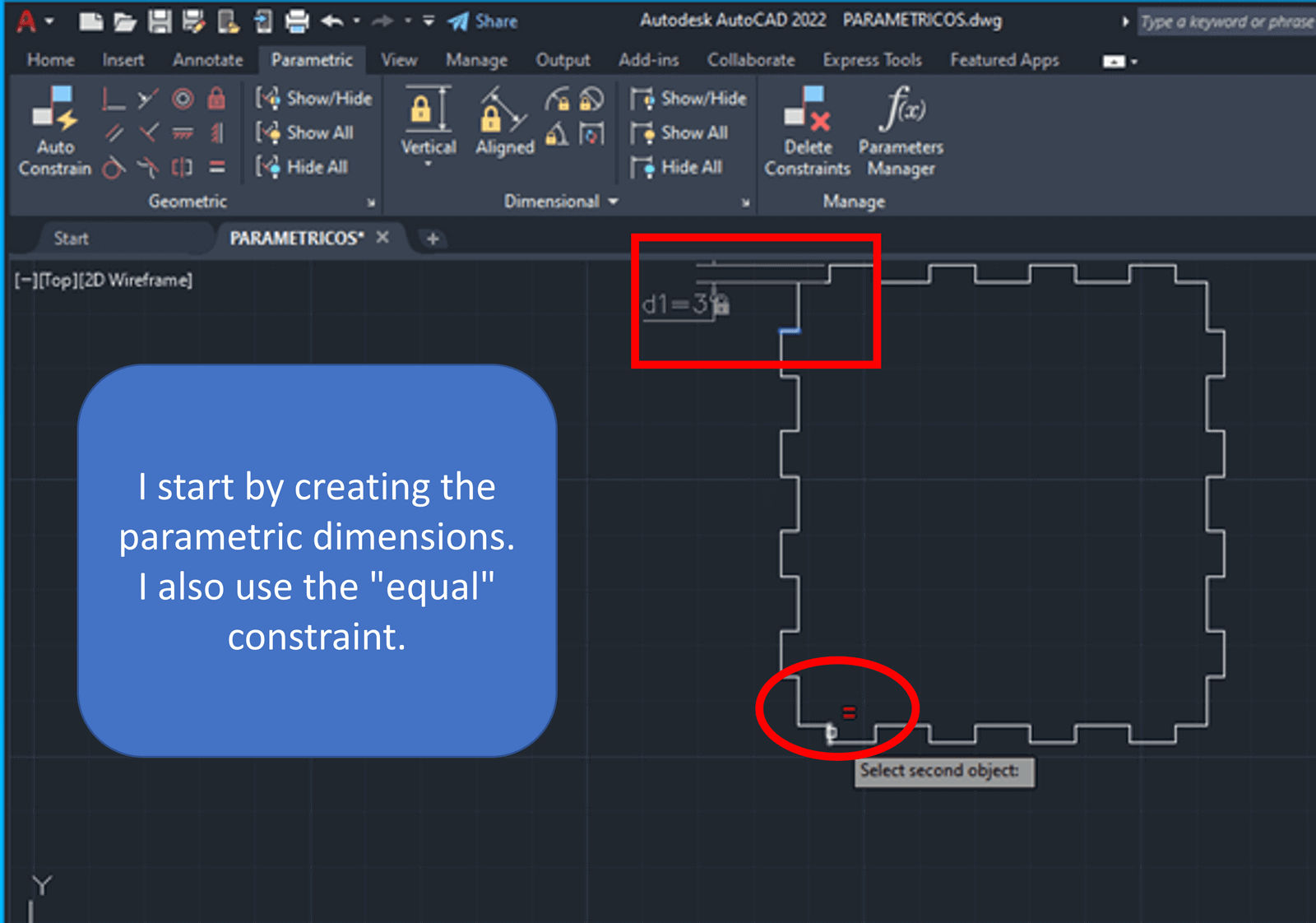
I start by creating a piece with the line command, after finishing the group, I go to "parametric" and within "geometric" I select the option "automatic constraints" and in design the following constraints are defined: collinear, parallel, perpendicular and horizontal.
Then I choose "linear" within "by dimension" in the "parametric" option and I begin to define the parametric dimensions for the different distances of the piece, I use the "equal" constraint within "geometric" to finish associating the constraint dimensions. It does not generate any error, my parametric design is correct.


I save this design with a .DXF extension so I can work
with it in Corel.
To place the letters within the design, my instructor
recommended that I work directly in Corel, and so I did.
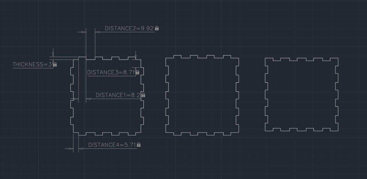
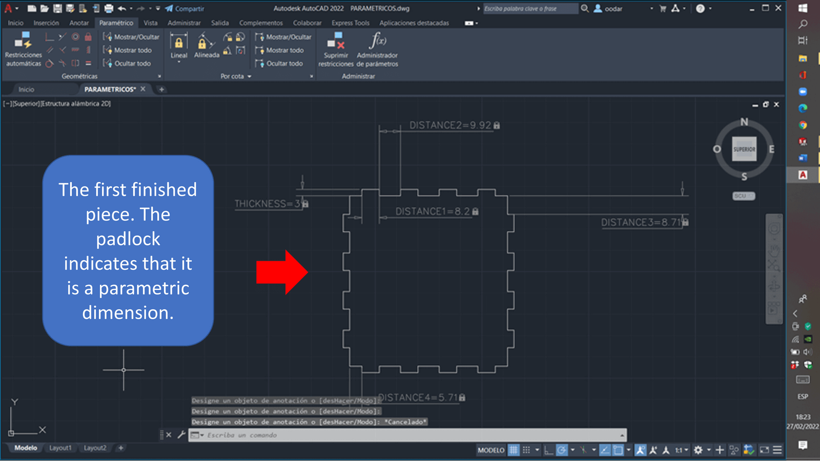
After parametrically designing the three pieces of my press-fit box, I save the file with a .DXF extension to later work on the file in Corel Draw.
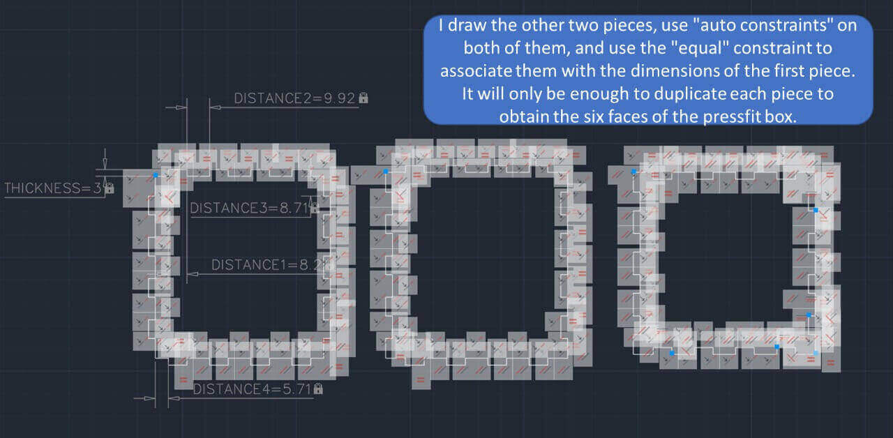
Once in Corel, we duplicate each piece (in this way we obtain the 6 faces of the box), and proceed to place the corresponding letters as my instructor recommended.
Now yes, my design is ready for laser cutting. 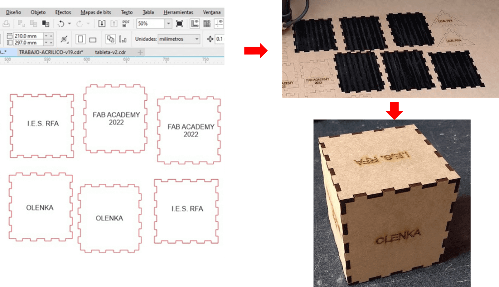
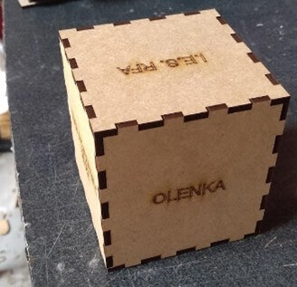
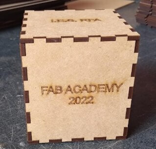

It should be noted that in the case of acrylic, the text to be engraved must have a minimum size of 3mm, to prevent the laser from damaging it.
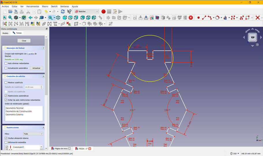
At the recommendation of my evaluator, I made a second pressfit kit. Since I had uninstalled Autocad, I decided to follow Neil's suggestion and work with FreeCAD; It was a pleasant experience, parametric design is really easy to implement with this software.
We open the program, and we configure the work area to carry out the drawing.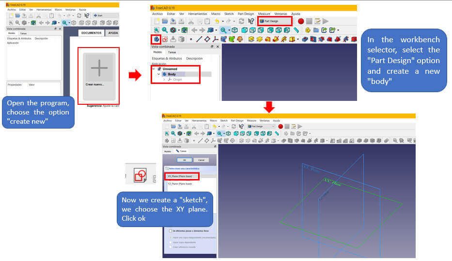 Finally the work area is configured as follows.
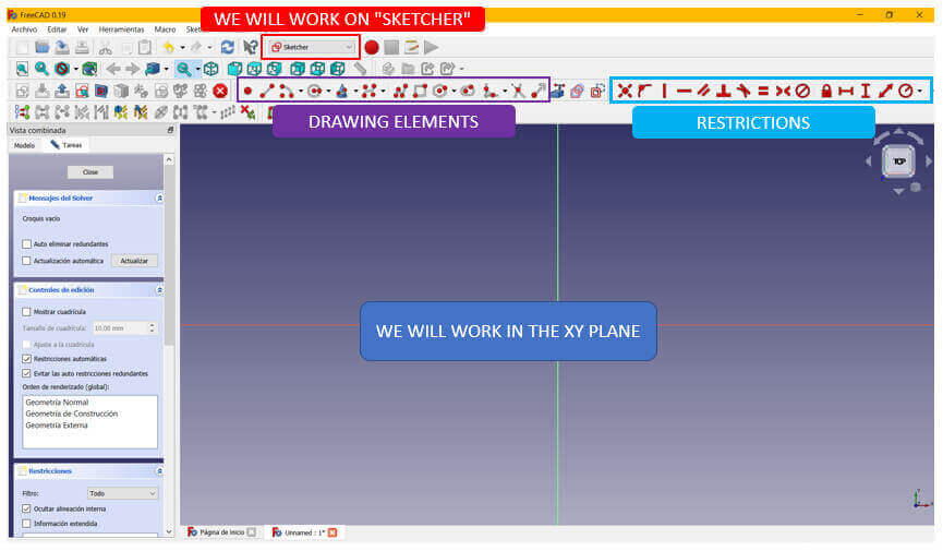
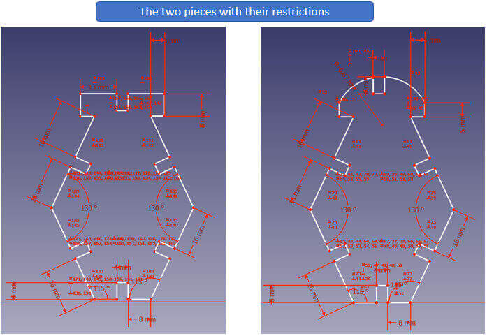
My test design was a triangle, I drew it following the idea of more or less how I wanted it to look. Then I started to apply the parametric restrictions and the figure was taking shape.
I start my drawing with the “Polyline” drawing tool. To create the restrictions, you must choose the restriction to apply and select on which part of our drawing it will be applied (lines, sides, angles, etc.).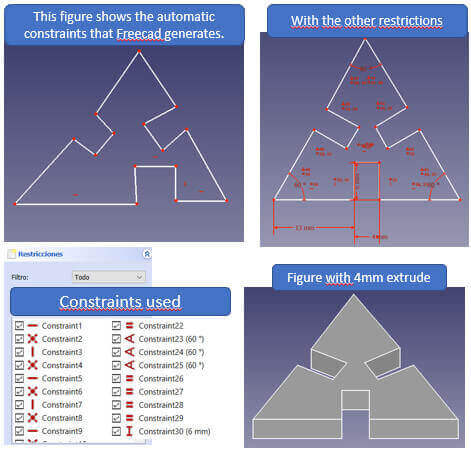
Since I didn't know what other figure to form, I ventured to make two figures similar to the star wars ship. I show you what I did.

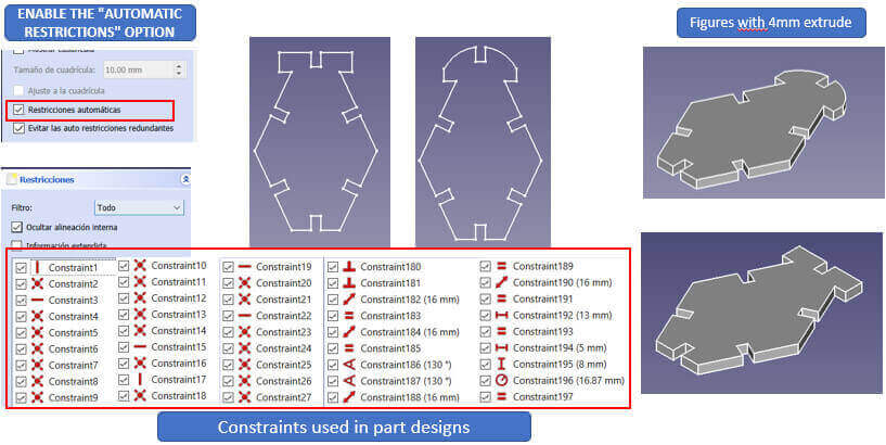
It is recommended to enable the "AUTOMATIC RESTRICTIONS" option when working in freecad; in this way the same software generates the default restrictions that our drawing needs.
When finishing the design of the pieces, we export them in DXF format, in this format you can work without any problem in the software of the laser cutter.

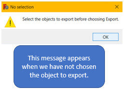
In order to cut the pieces, we import the DXF files into the software of the laser cutting machine.
After loading the DXF file into the laser cutting software, I performed the following steps:
1. Configure speed and power parameters
2. Select the lines that should be cut
3. Save and send the file to the laser cutter
4. Set the origin of the cut on the material
5. Start the laser
As i had already used 3mm MDF, this time i used 4mm cardboard. I made the first cut on the laser cutter with the following parameters: cutting speed of 5 mm/s and 60% of the laser power. It did not go so well as the pieces were burned in some places.

After several tests I found the correct values: cutting speed of 7 mm/s and 50% of the laser power.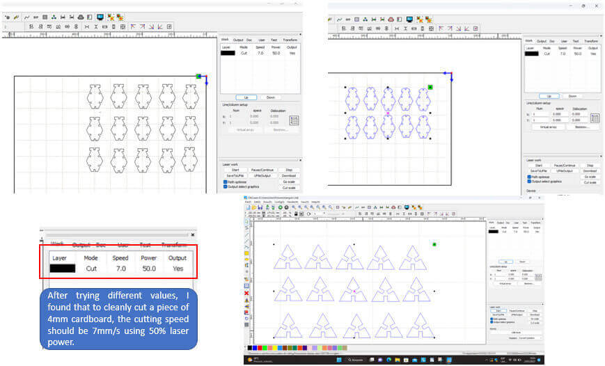
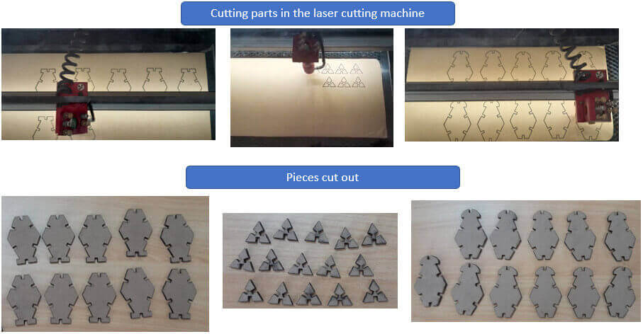
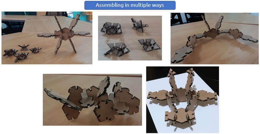
Finally, these are some of the things I put together with my pieces.
1. I liked working with FreeCAD, especially because of how convenient it is to use the parametric constraints.
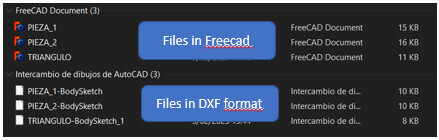
2. Make sure to save each piece made in FreeCAD separately, so when exporting in DXF format it will be easier to work with the file in the laser cutter software.
3. It must be taken into account that the cutting parameters vary according to the type of material and its thickness. By not setting the parameters correctly, the material can be burned and a fire could start.
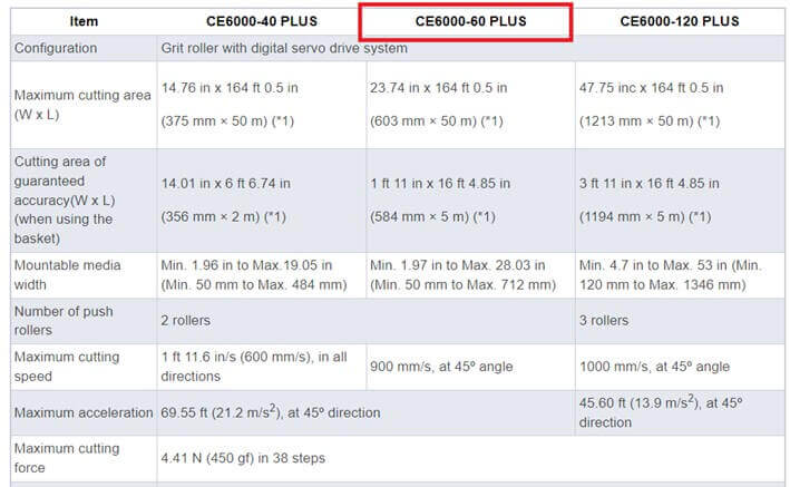
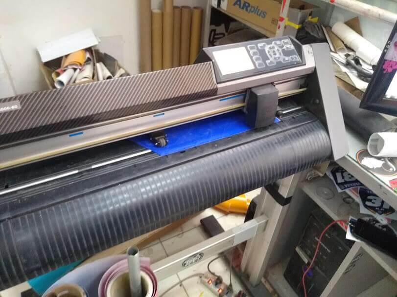
Marca: Graphtec
Modelo: CE6000-60
Parámetro técnico:


The files to be worked on vinyl must be previously vectorized in corel draw, it must be avoided that the image has many fill details so that the machine does not work much. These images were worked by layers in vinyl of different colors.
Redrawing to be able to cut by layers of colors.
![]()
The layers of different colors that make up the logo are cut separately.

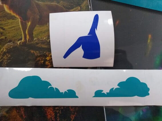
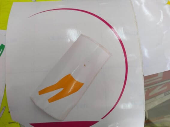
Each layer of a different color is glued until the logo is shaped.

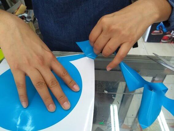
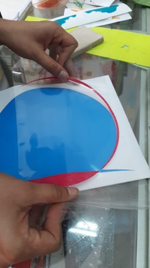
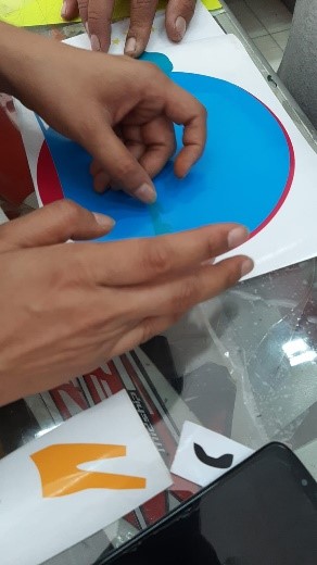
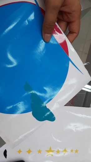
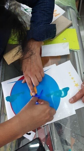
The adhesive plastic used to join the layers is called TRANSFER.
![]()
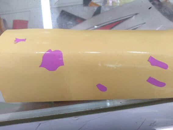
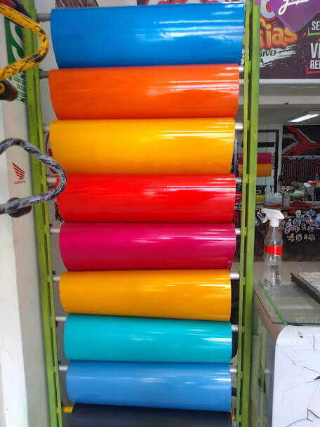
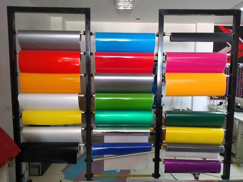
Here images of the different colors of vinyl.

File download links
created with
Best Website Builder .