In this section we list the activities to be solved in the following table:
| Checklist | Estatus |
|---|---|
| Linked to the group assigment page | Finished |
| Documented how you determined power consumption of an output device with your group | Finished |
| Documented what you learned from interfacing output device(s) to microcontroller and controlling the device(s) | Finished |
| Described your design and fabrication process or linked to previous examples. | Finished |
| Explained the programming process/es you used. | Finished |
| Explained any problems you encountered and how you fixed them. | Finished |
| Included original design files and code | Finished |
| Included a 'hero shot/video' of your borad | Finished |
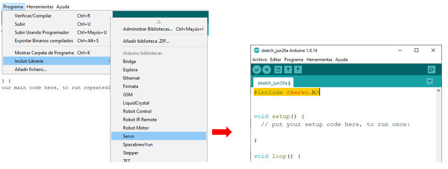
Add an output device to a microcontroller board you’ve designed and program it to do something.
For this part I will use the Fab XIAO RP2040 board that I made in electronic production and the following devices:
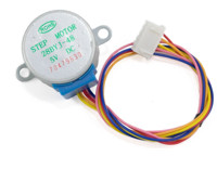
It is an electromechanical device that converts electrical pulses into discrete mechanical movements. The shaft or spindle of a stepper motor rotates in discrete step increments when electrical pulses are applied to it in the proper sequence and at the proper time intervals.
learn more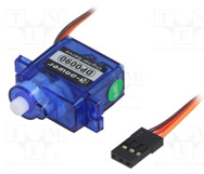
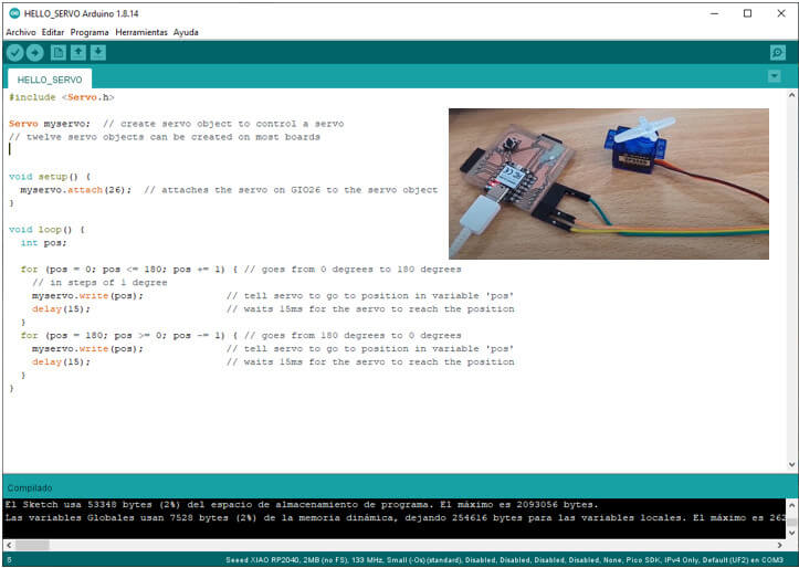
A servo motor (0 to 180 degrees) is a device that has the ability to move to any position within its operating range and remain stable in that position.
learn more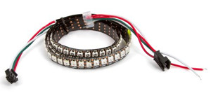
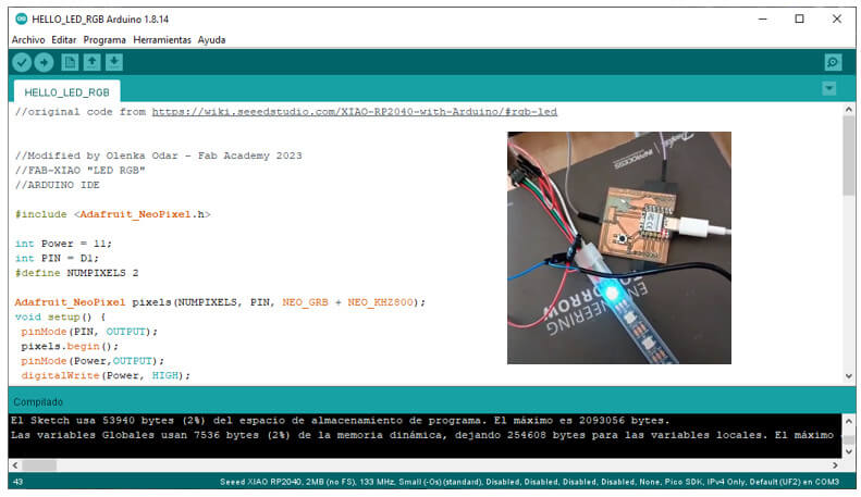
The strip of RGB LEDs, which can be individually controlled using a single-cable interface, giving you full control over the color of each RGB LED.
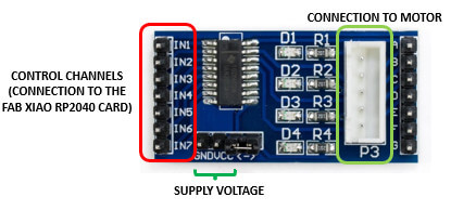
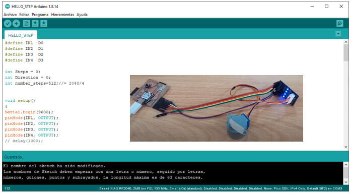
learn moreThis device works with the ULN2003 Driver, a driver specially designed to drive the 28BYJ-48 (unipolar) stepper motor. It works at 5V and has up to 7 control channels, in my case I used the IN1, IN2, IN3 and IN4 channels connected respectively to the D0, D1, D2 and D3 pins of my card. Do not forget to feed the card at 5V. The connection is very simple.
This device only consists of 3 cables: GND, VCC and a third one for the signal output that will be connected to pin D0 (GPIO 26). I take as a base the program modified by Adrián Torres to make it work.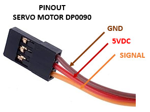
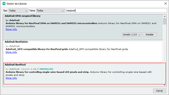
My project consists of making a lamp for children who are afraid of the dark. But what can I use so that the lamp illuminates, in different colors and shapes and also does not need many connections? An interesting alternative is this RBG led strip because I can independently control each led with a single control cable.
I used a 20 led strip, it comes with a projector and works with a 5V voltage; it has three wires: 5V (red wire), GND (white wire), and a control pin (green wire). 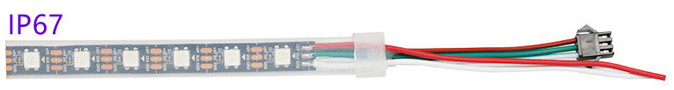
I made a small test program, after several tries you can manage to activate two leds.
- Measure the power consumption of an output device.
- Document your work on the group work page and reflect on your individual page what you learned.
I will also do this assignment individually.
To know the power consumption of the servomotor, I used the multimeter connecting it as shown in the figure (we must measure in series, that is, the circuit will be closed through the multimeter).
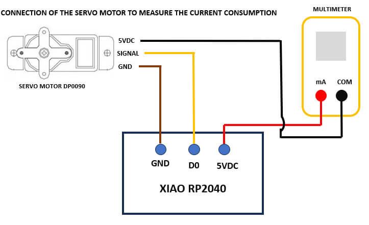
When making the measurements, the current varies from 18.66mA to 49.17mA.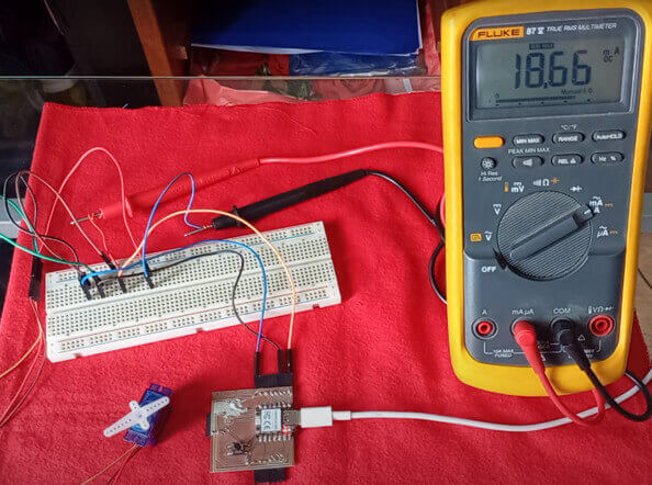
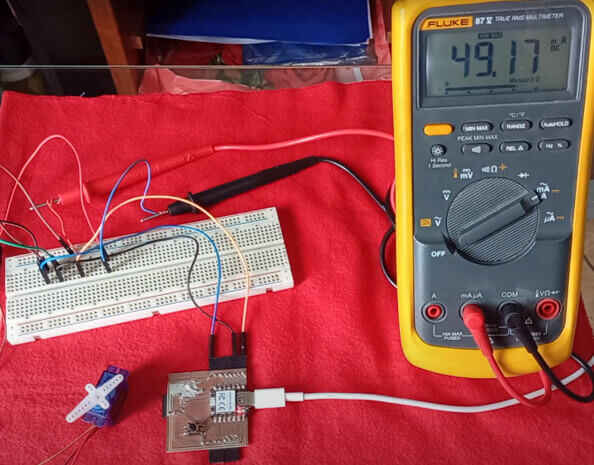
To find the energy consumption, we must use the formula: P = I x V.
Taking the highest current consumption 49.17mA and the supply voltage of 5V, we have:
Converting to amps.
P = 5V x 0.4917A
P = 0.24585 W
Finally, I use the oscilloscope to see the variation of the frequencies when the servo moves, for this I place one end of the oscilloscope on pin D0 and the other on GND.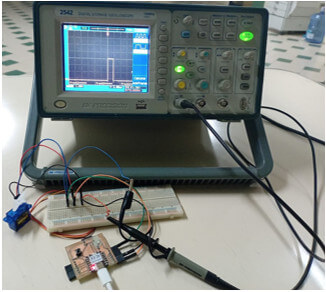
Here the images of the output signal from pin D0 are shown, configuring the oscilloscope to see the waveform in "multiple cycle" (image on the left) and as "single cycle" (image on the right).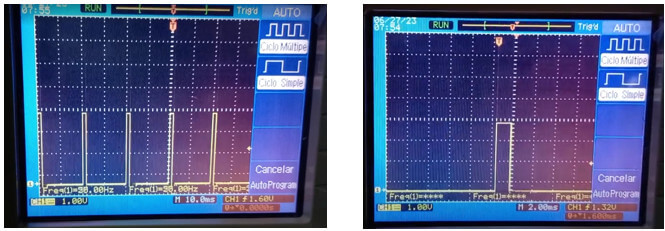
In the video I configured the oscilloscope to see the wave as "simple cycle" since the variation of the pulse width is better appreciated.
created with
HTML Designer .