In this section we list the activities to be solved in the following table:
| Checklist | Estatus |
|---|---|
| Linked to the group assignment page. | Finished |
| Documented your process. | Finished |
| Explained the GUI that you made and how you did it. | Finished |
| Explained how your application communicates with your MCU board. | Finished |
| Explained any problems you encountered and how you fixed them. | Finished |
| Included original source code (or a screenshot of the app code if that's not possible). | Finished |
| Included a ‘hero shot’ of your application running & communicating with your board. | Finished |
- Compare as many tool options as possible.
- Document your work on the group work page and reflect on your individual page what you learned.
I will also do this assignment individually.
Node-RED is a flow-based programming tool, which is implemented on hardware controller devices. Originally developed by the IBM Emerging Technology Services team and now part of the OpenJS Foundation.
It is a flow panel to which nodes that communicate with each other can be incorporated and can be installed on computers such as Windows, Linux or on cloud servers.
Being a tool designed to communicate hardware, it allows programming, connectivity and services to be simplified; It has become the open-source standard for processing data in real time.
The Node-RED software allows communication through the serial port as well as the creation of boards that allow data to be sent and received.
The first thing we need to do is install the software, go to the NODE JS page, and download the latest version.
Once the download is complete, we proceed to install the software.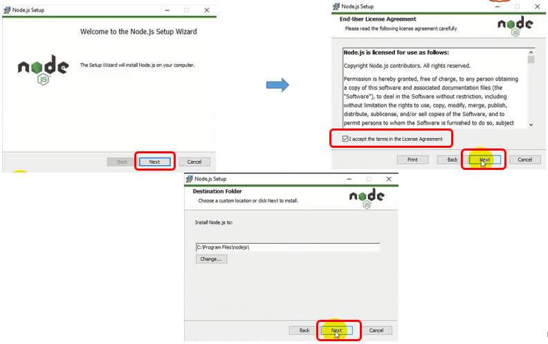
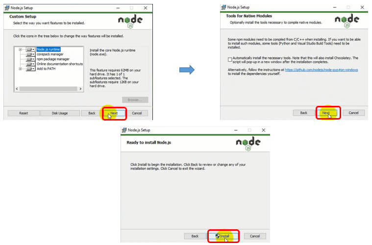
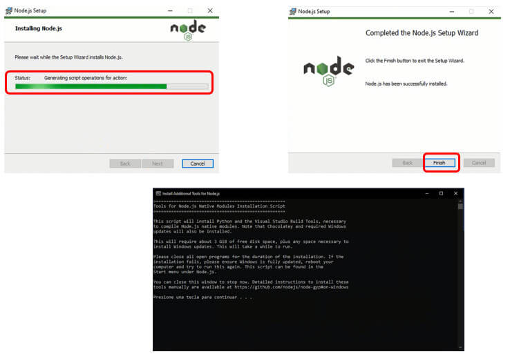
Once the installation is finished, we enter the Windows console (CMD) and execute the following command: npm install –g –unsafe-perm node-red
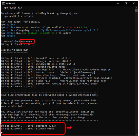
 After the command has been executed successfully, issue the command: node-red to run the software.
In the web browser type: 127.0.0.1:1880, this is the home screen that should appear. We are ready to create our first Flow.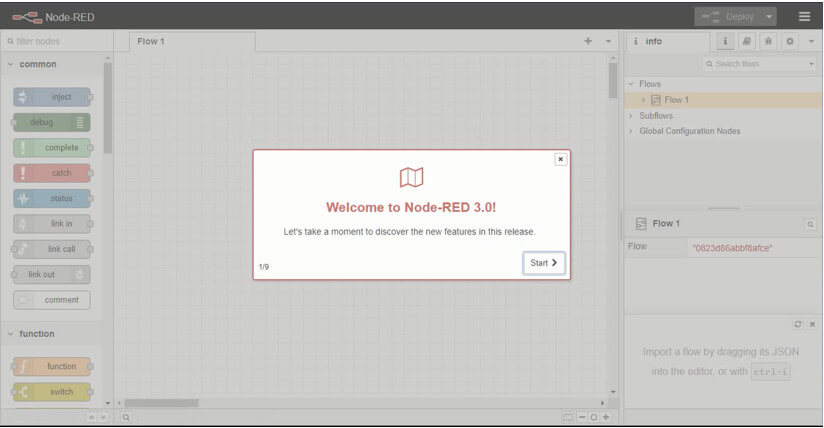
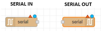
For serial communication we will use the nodes serial in (to read data) and serial out (to send data)
For my test with this interface I will try to control the lighting of 4 leds, here are the steps to create the corresponding dashboard (the dashboard block is a special block that must be installed: node-red-dashboard)
First we enter the dashboard panel, then click on "Tab" to create the "CONTROL LED" tab, click on UPDATE.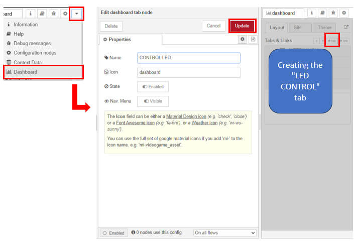
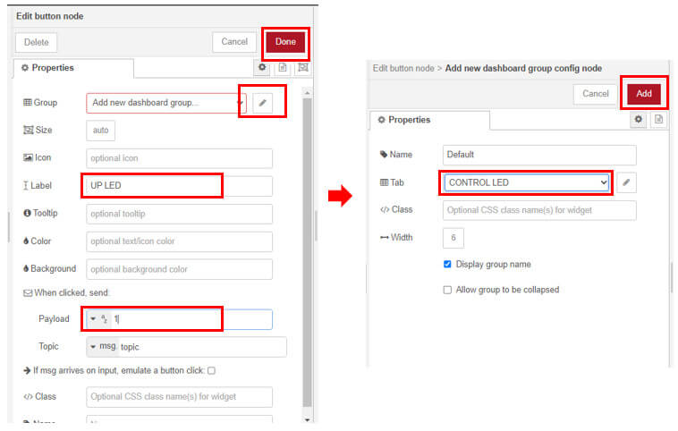
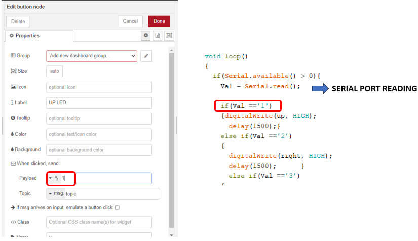
Now with the help of the "button" dashboard we will create the controls for turning the four leds on and off. Each one of them must be edited and grouped in the "LED CONTROL" tab, in the payload we will leave it as a string and we will place 1-4 for each button that turns on a led and 0 for the button that turns off the leds. We then bind them to the serial out node.
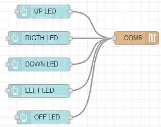
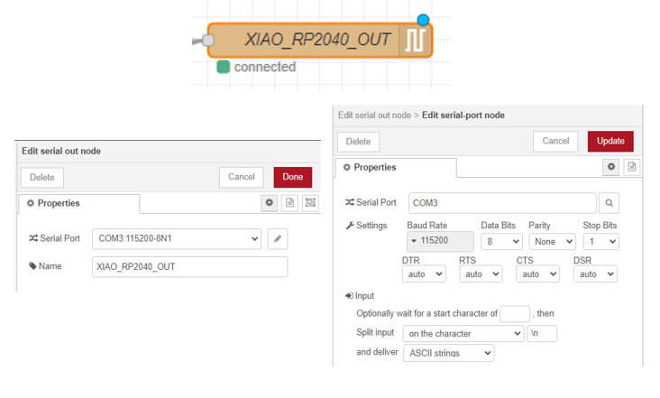
Finally we must edit the serial out node, here the only thing we will do is choose the COM port that our card uses and the baud rate.
Do not forget that to save the changes you must click on deploy.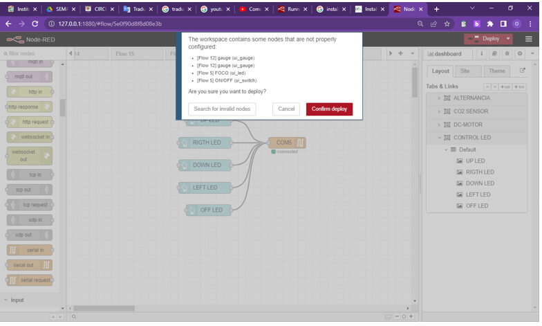
We connect our card with the previously loaded program, and the serial out node should connect without problems.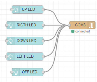
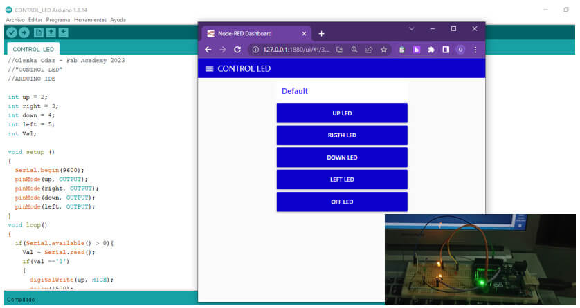
This is the dashboard created to control the on and off of the LEDs.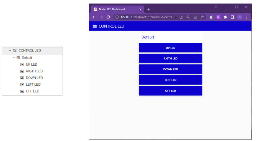
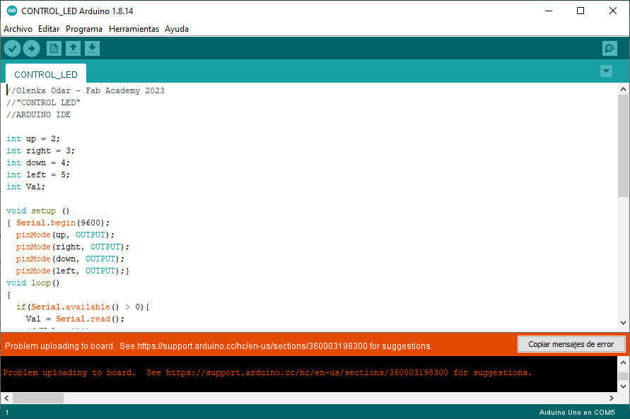
//Olenka Odar - Fab Academy 2023
//"CONTROL LED"
//ARDUINO IDE
int up = 2;
int right = 3;
int down = 4;
int left = 5;
int Val;
void setup ()
{ Serial.begin(9600);
pinMode(up, OUTPUT);
pinMode(right, OUTPUT);
pinMode(down, OUTPUT);
pinMode(left, OUTPUT);}
void loop()
{ if(Serial.available() > 0){
Val = Serial.read();
if(Val =='1')
{digitalWrite(up, HIGH);
delay(1500);}
else if(Val =='2')
{
digitalWrite(right, HIGH);
delay(1500); }
else if(Val =='3')
{ digitalWrite(down, HIGH);
delay(1500); }
else if(Val =='4')
{ digitalWrite(left, HIGH);
delay(1500); }
else
{
digitalWrite(left, LOW);
digitalWrite(down, LOW);
digitalWrite(right, LOW);
digitalWrite(up, LOW);
delay(1000);} } }
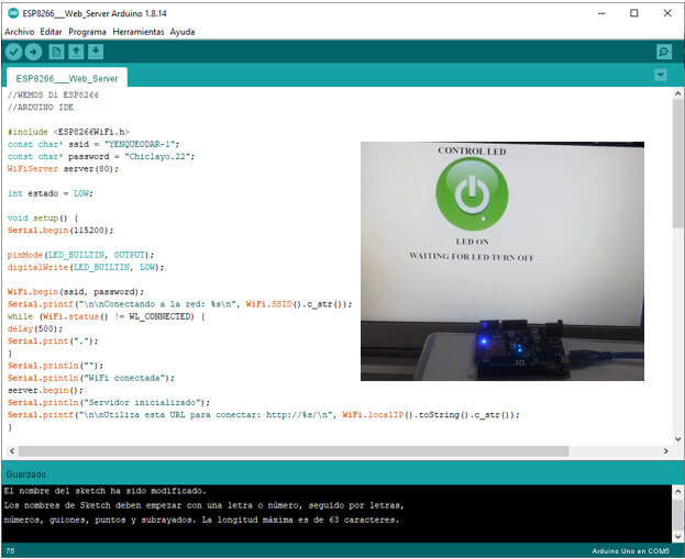
Wemos D1 can be programmed using the Arduino IDE. In this way, we can take advantage of the code made for arduino and take it to this card easily. To work with the WEMOS D1 ESP8266 card with the Arduino IDE, we must first configure and install the necessary libraries and drivers so that our card can be recognized and programmed. I based it on a YouTube video, he left the link.
After downloading and decompressing the files, we proceed to install the driver. 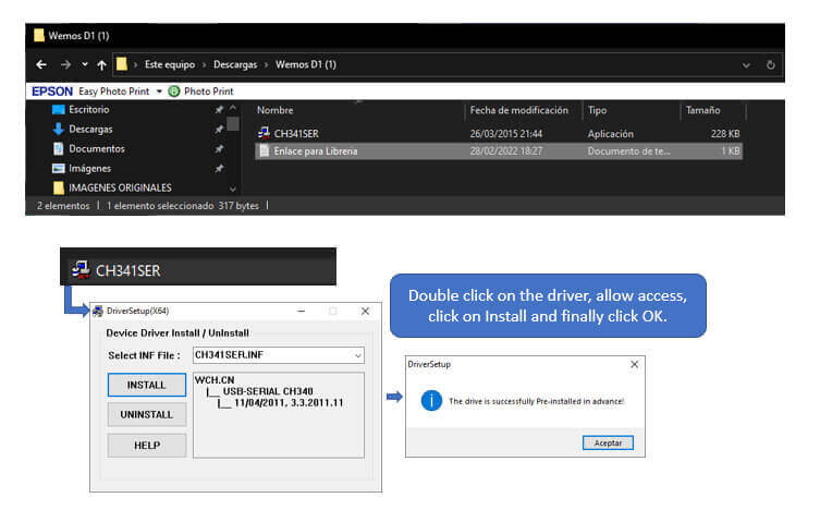
Now we enter, from the Arduino IDE, the link in the card additional URLs manager. 
To work with the WEMOS D1 ESP8266 card with the Arduino IDE, we must first configure and install the necessary libraries and drivers so that our card can be recognized and programmed. I based it on a YouTube video, he left the link. We install the ESP8266 card library.

This card integrates an ESP8266 Wi-Fi module, so I will make an interface that allows me to control a led from the web. Once we load the program to the card, we enter the serial monitor to obtain information on the address of the internet page that we must access to control the on and off of the led, if the information does not appear, just press the reset button the card and the information will appear. Do not forget that it is necessary that we place the serial communication at 115200 baud.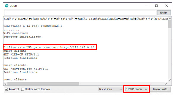
I searched for the on/off images that appear on the internet and copied the address of the image, but since it was too long, I shortened the URL with the following online program "Acortar.link URL", and it worked correctly. 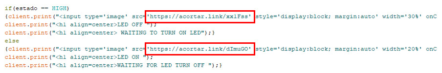
//WEMOS D1 ESP8266
//ARDUINO IDE
#include <ESP8266WiFi.h>
const char* ssid = "YENQUEODAR-1";
const char* password = "Chiclayo.22";
WiFiServer server(80);
int estado = LOW;
void setup() {
Serial.begin(115200);
pinMode(LED_BUILTIN, OUTPUT);
digitalWrite(LED_BUILTIN, LOW);
WiFi.begin(ssid, password);
Serial.printf("\n\nConectando a la red: %s\n", WiFi.SSID().c_str());
while (WiFi.status() != WL_CONNECTED) {
delay(500);
Serial.print(".");
}
Serial.println("");
Serial.println("WiFi conectada");
server.begin();
Serial.println("Servidor inicializado");
Serial.printf("\n\nUtiliza esta URL para conectar: http://%s/\n", WiFi.localIP().toString().c_str());
}
void loop()
{
WiFiClient client = server.available();
if (!client) {
return;
}
Serial.println("nuevo cliente");
while(!client.available()){
delay(1);
}
String peticion = client.readStringUntil('\r');
Serial.println(peticion);
client.flush();
if (peticion.indexOf('/LED=ON') != -1)
{estado = LOW;}
if (peticion.indexOf('/LED=OFF') != -1)
{estado = HIGH;}
digitalWrite(LED_BUILTIN, estado);
client.println("HTTP/1.1 200 OK");
client.println("");
client.println("");
client.println("");
client.println("");
client.print("<h1 align=center>CONTROL LED ");
//client.print("<h1 align=center>CONTROL LED33 ");
if(estado == HIGH)
{client.print("<input type='image' src='https://acortar.link/xx1Fss' style='display:block; margin:auto' width='30%' onClick=location.href='/LED=ON'>");
client.print("<h1 align=center>LED OFF ");
client.print("<h1 align=center> WAITING TO TURN ON LED");}
else
{client.print("<input type='image' src='https://acortar.link/dImuGO' style='display:block; margin:auto' width='20%' onClick=location.href='/LED=OFF'>");
client.print("<h1 align=center>LED ON ");
client.print("<h1 align=center>WAITING FOR LED TURN OFF ");}
client.println("</html>");
delay(1);
Serial.println("Peticion finalizada"); // Se finaliza la petición al cliente. Se inicializa la espera de una nueva petición.
Serial.println("");
}
Processing is an open source programming language and integrated development environment. Based on Java oriented graphics programming and interaction; it was created as a digital tool for artists and designers.
The first thing to do is to download the program, we go to the official page of Processing, click on downloads and choose to download Processing 4.3 for windows (you can also download versions for macOS, Linux and Raspberry Pi). Once the download is finished, unzip the zip folder, enter the folder and click on the Processing icon and that's it.
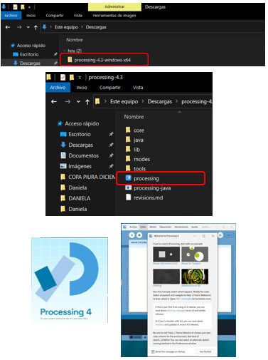
The program presents the following working environment:

All processing programs have a common structure, first it is important to define the Variables and Libraries (it is important to use the Processing.serial library ), then the void setup and finally the void draw. Some important concepts:
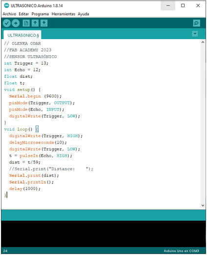
Low-cost distance sensor that uses ultrasound to determine the distance of an object in a range of 2 to 450 cm. Based on the following formula we can find the distance traveled. This will help us in the Arduino programming.
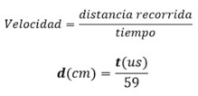
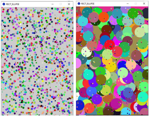
For my test with this interface, I will draw random squares and spheres, of variable size (the size will depend on the value of the distance obtained with the ultrasonic sensor) and random color. If the distance is less than 50 cm, squares will be drawn and if it is equal or greater than 50cm, spheres will be drawn. I took as a guide the work done by Adrian Torres, but in my case I used an ultrasonic sensor.
Basic commands used in this program:
Do not forget that before starting the program it is necessary to import the library that allows us to work with the serial port. I show the screens of the program in Processing.
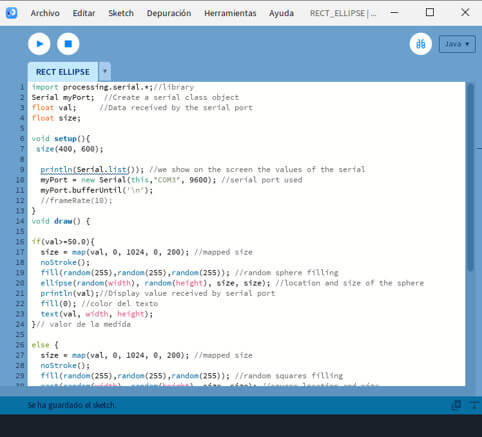 As Adrian indicates, after the void draw, do not forget the following program lines, to achieve the serial communication with the Arduino board.
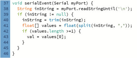
//OLENKA ODAR
//FAB ACADEMY
//RECT_ELLIPSE
import processing.serial.*;//library
Serial myPort; //Create a serial class object
float val; //Data received by the serial port
float size;
void setup(){
size(400, 600);
println(Serial.list()); //we show on the screen the values of the serial
myPort = new Serial(this,"COM3", 9600); //serial port used
myPort.bufferUntil('\n');
//frameRate(10);}
void draw() {
if(val>=50.0){
size = map(val, 0, 1024, 0, 200); //mapped size
noStroke();
fill(random(255),random(255),random(255)); //random sphere filling
ellipse(random(width), random(height), size, size); //location and size of the sphere
println(val);//Display value received by serial port
fill(0); //color del texto
text(val, width, height);
}// valor de la medida
else {
size = map(val, 0, 1024, 0, 200); //mapped size
noStroke();
fill(random(255),random(255),random(255)); //random squares filling
rect(random(width), random(height), size, size); //square location and size
println(val);//Display value received by serial port
fill(0); //color del texto
text(val, width, height); }}
void serialEvent(Serial myPort) {
String inString = myPort.readStringUntil('\n');
if (inString != null) {
inString = trim(inString);
float[] values = float(split(inString, ","));
if (values.length >=1) {
val = values[0];
}
}
}
OLENKA ODAR
//FAB ACADEMY 2023
//SENSOR ULTRASÓNICO
int Trigger = 13;
int Echo = 12;
float dist;
float t;
void setup() {
Serial.begin (9600);
pinMode(Trigger, OUTPUT);
pinMode(Echo, INPUT);
digitalWrite(Trigger, LOW);
}
void loop() {
digitalWrite(Trigger, HIGH);
delayMicroseconds(10);
digitalWrite(Trigger, LOW);
t = pulseIn(Echo, HIGH);
dist = t/59;
//Serial.print("Distance: ");
Serial.print(dist);
Serial.println();
delay(1000);
}
This will show the processing at different distances detected by the ultrasonic sensor.
After comparing these interfaces, I decided to do my individual assignment with Node-Red. Why? Because when I reviewed different tutorials, I could see that it can be used in process automation, since there are specific nodes for reading and writing data to a programmable logic controller. Therefore, I decided to learn more about this environment in order to apply it to the courses I teach.
Write an application that interfaces a user with input and/or output device(s) on a board that you made.
What to do? I had seen on the internet that communication can be established through the serial port of my FAB XIAO RP2040 card with the Node-RED software and that control boards can also be created to receive and send data, so I decided to do my assignment with Node-RED. But first I had to make sure that it is allowed to use that software and what do you think? Yes it can!!!
Let us begin!!
For this assignment I will work with:
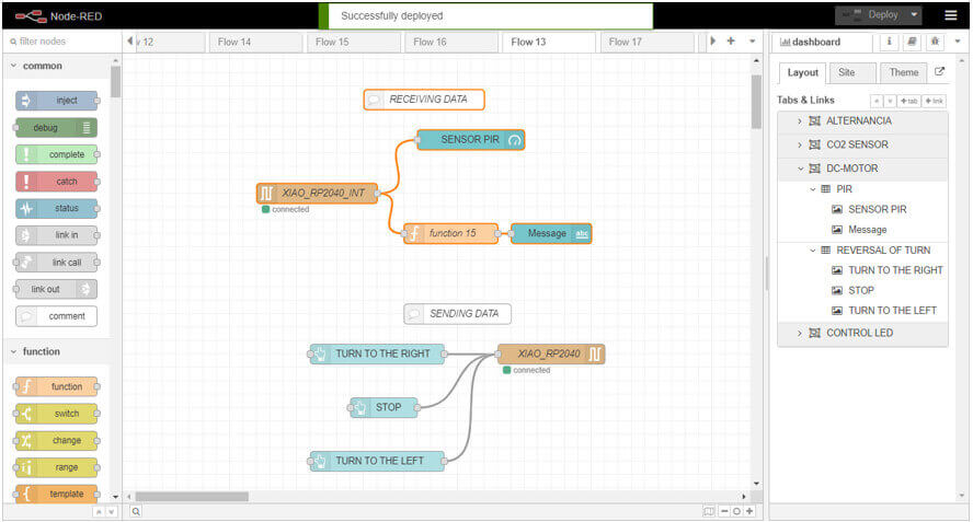
Next I will describe the creation of the interface in Node-red:
The interface consists in that every time the sensor is activated when an object is detected on the screen, the message "object detected" should appear, otherwise the message will be "object not detected". To achieve this I will use the serial input node in which the port to be used will be configured, the baud rate and a name will be assigned to it.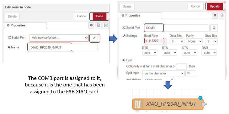
We will also use a gauge node, a function node and a text node which will be configured as follows. Click n done. To save all the changes click on deploy.
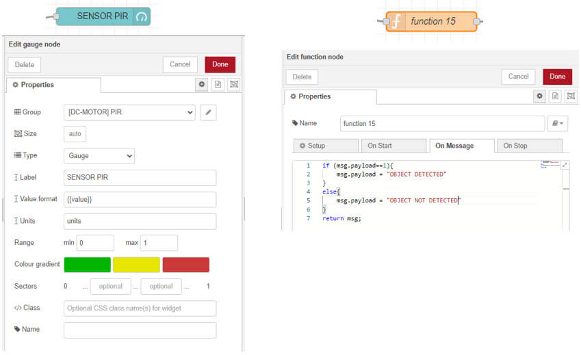
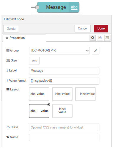
All these nodes will allow the creation of the dashboard to visualize the operation of the PIR sensor.
// Fab Academy 2023 - Olenka odar // Fab Academy 2023 - Olenka odar // Fab Academy 2023 - Olenka odar
int pir = D0;
int val_pir;
void setup() {
Serial.begin(115200);
pinMode(pir, INPUT);
pinMode(led,OUTPUT);
for(int i = 0; i > 60; i++)
{delay(1000);
}
delay(50);}
void loop() {
val_pir=digitalRead(pir); //read pin status
if(val_pir==HIGH){
Serial.println(val_pir);
delay(150); }
else{
Serial.println(val_pir);
delay(150); } }

For this part I will need:
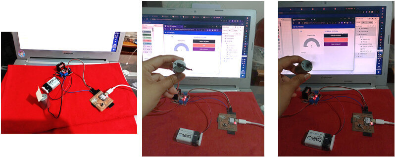
With Node - Red, I'll try to make a reversal of a 9v DC motor.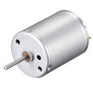
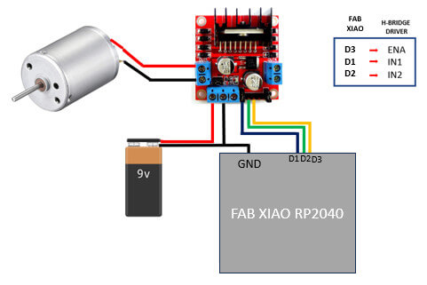
Before starting it is necessary to indicate how the DC motor will be connected, this is an output device that can be controlled by my Fab XIAO card. Through the L298N H-bridge driver. I indicate the characteristics of the driver and connection with the dc motor.
To use this driver, the following information must be taken into account:
Ways to power the module:
1. Using a single source, connected to the 12V input and with the Jumper to enable the regulator, clarifying that the source voltage is the one that supports the motor. In this way, the 5V input must not be connected to any source, since 5V is present on this pin through the internal regulator; but you can use this pin as a 5V output, but without exceeding the 500mA consumption. It is recommended to make this connection for voltages lower than 12V so as not to overheat the regulator.
2. Using two sources, one of 5V connected to the 5V input (it can be the 5V of an Arduino) and another source with the value of the voltage that works the motor, connected to the 12V pin. For this, the Jumper must be disconnected, which will disable the regulator.
For module control:
1. The ENA, IN1, IN2 pins correspond to the inputs to control MOTOR A (OUT1 and OUT2)
2. In the same way ENB, IN3, IN4 allow to control MOTOR B (OUT3 and OUT4)
3. ENA and ENB, are used to enable or disable their respective motors, they are generally used to control the speed, entering a PWM signal through these pins. If they are not used, the Jumpers must be connected so that they are always enabled.
I got this information from the following tutorial.
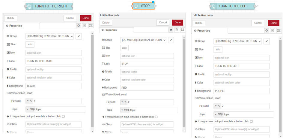
Now we have to create the dashboard for the motor control, for this I will use the serial out node and three button nodes, the configuration of each of them is shown.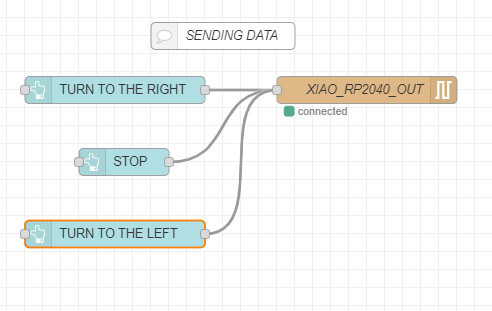
// Fab Academy 2023 - Olenka Odar
int in1 = D1; // Pin that controls the direction of rotation Motor
int in2 = D2; // Pin that controls the direction of rotation Motor
int ENA = D3;
int Val;
void setup ()
{ Serial.begin(9600);
pinMode(in1, OUTPUT);
pinMode(in2, OUTPUT);
pinMode(ENA, OUTPUT);}
void loop()
{ if(Serial.available() > 0){
Val = Serial.read();
if(Val =='2')
{ analogWrite(ENA,75);
digitalWrite(in1, HIGH); // RIGHT
digitalWrite(in2, LOW);
delay(1500); }
else if(Val =='1')
{ analogWrite(ENA,75);
digitalWrite(in1, LOW); // LEFT
digitalWrite(in2, HIGH);
delay(1500); }
else
{ analogWrite(ENA,75);
digitalWrite(in1, LOW); // STOP
digitalWrite(in2, LOW);
delay(1000);
} } }
This is the final dashboard, it contains both the display of the PIR sensor data and the control of the reversal of the DC motor.

Programming in Node-red

created with
WYSIWYG HTML Editor .