Mechanical Design / Machine Design
Group Assignment 2021 (Héctor and Gustavo)

Personal sites: [Hector Flores] [Gustavo Salcedo]
CURIOSITY
The logo makes a little "joke" between the word "strawberry" and the "milling bit", which in Spanish are called the same, "strawberry", like fruit.
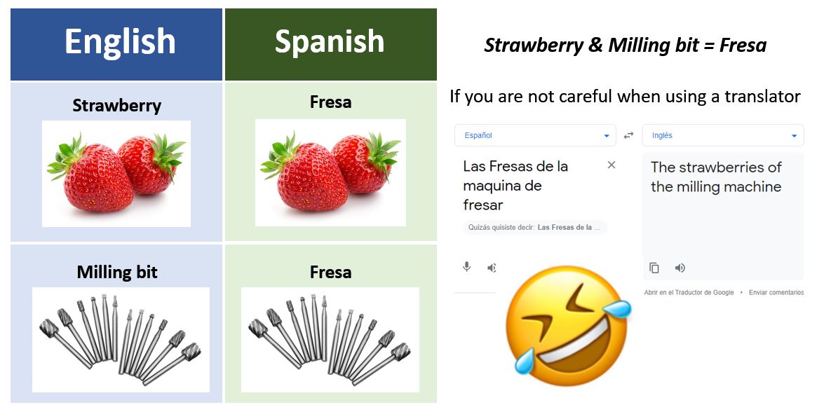
Strawberry Milling Machine Teaser:
Introduction
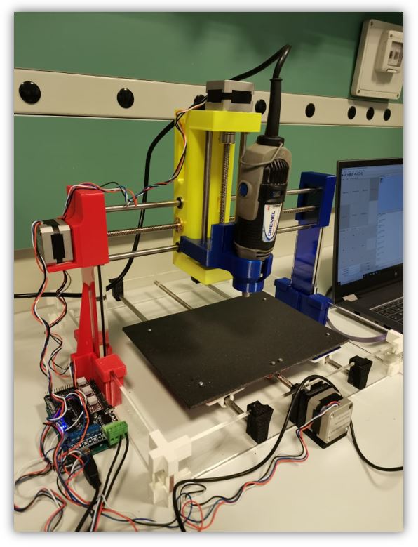
In our case we have created the Strawberry Milling Machine. A CNC machine for small milling jobs that can be built with acrylic material (made by laser cutting) and PLA thermoplastic parts (made by 3D printing).

Methodology
The flow of the work methodology has been as follows:
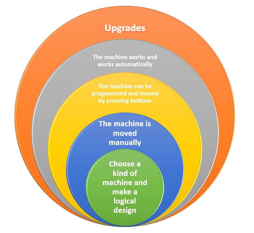
First of all, we have chosen the type of machine that we want to design and manufacture and we have established a scheme of 5 spirals, to mark the objectives of the machine.
With the objectives, we have started to make some first sketches and ideas, to identify the shape of our machine and the possible materials to use.
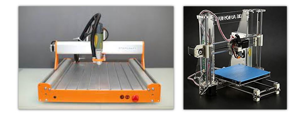
Inspiration
We have distributed tasks. Although we have both been present throughout the development, each one has focused on a few tasks to work in parallel and save time.
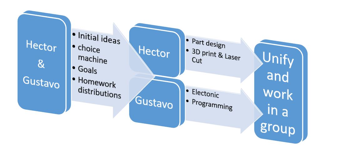
Through the use of Solidworks the parts of the machine have been developed. All parts have been designed from scratch. The advantage of designing all the pieces is the possibility of knowing all their dimensions and being able to carry out an assembly to check how they work (digitally).
Parallel to the design of the parts, the Arduino programming and the operation of the motors have been worked to verify that they communicate by USB and work correctly.
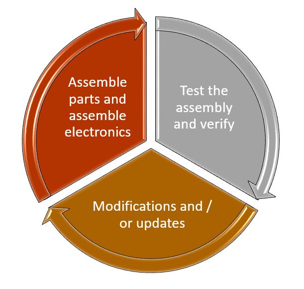
Finally, the Strawberry Milling Machine has been assembled, tested manually and with computer controlled movement before testing the automatic working mode.
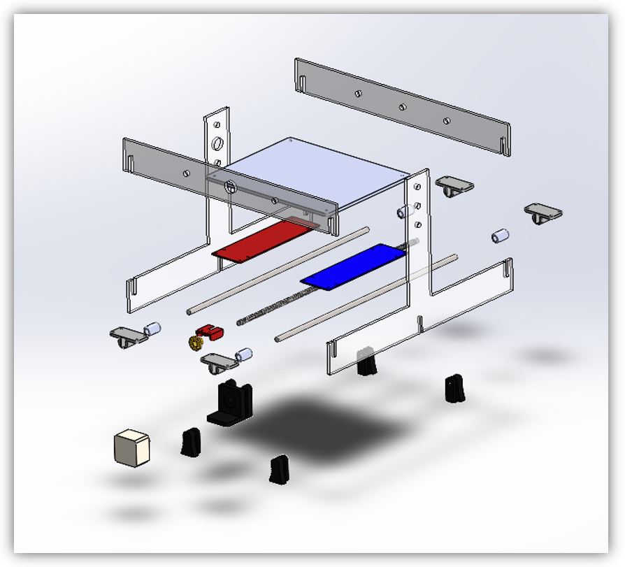
Design of the parts
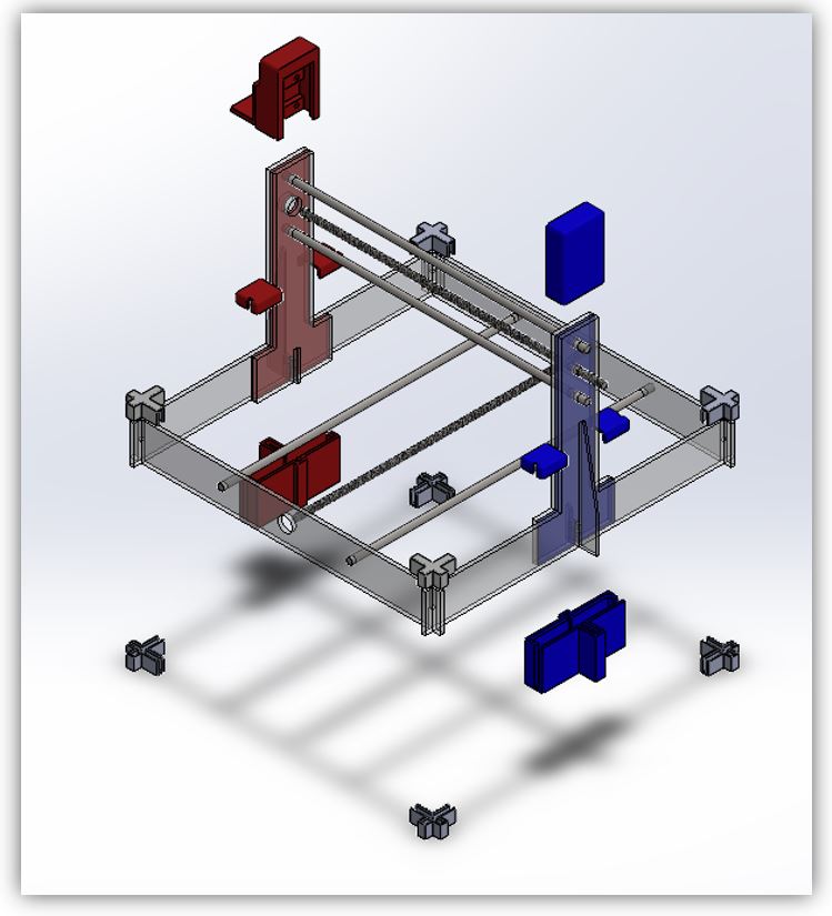
The first steps in the design have been the creation of the main structure of the milling machine.
They are designed for acrylic material, laser cut and press fit. They do not need screws. The use of glue is optional; we have not used glue.
The pieces are 5mm acrylic and the two colored pieces are 3mm acrylic.
Placement of the acrylic structure and the rods.
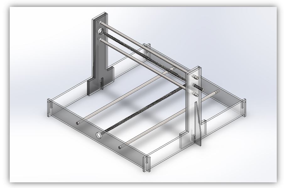
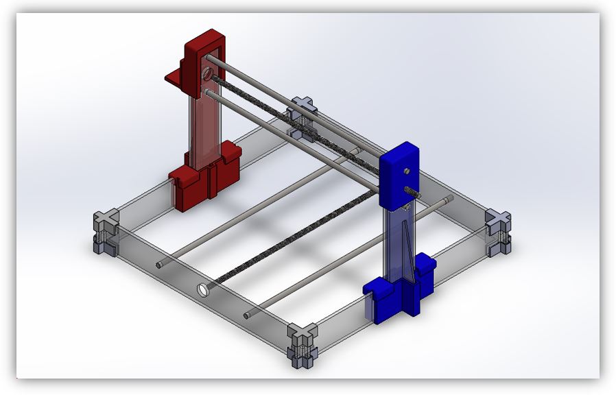
Assembly of the acrylic structure and the rods.
Two 8mm diameter rods are needed to cut to size, when coupled to motors. Also 4 non-threaded rods to favour linear movement.
Although the adjustment is by press fit, to reinforce stability, press fit reinforcement pieces have been created to aid the structure.
Reinforcement pieces.
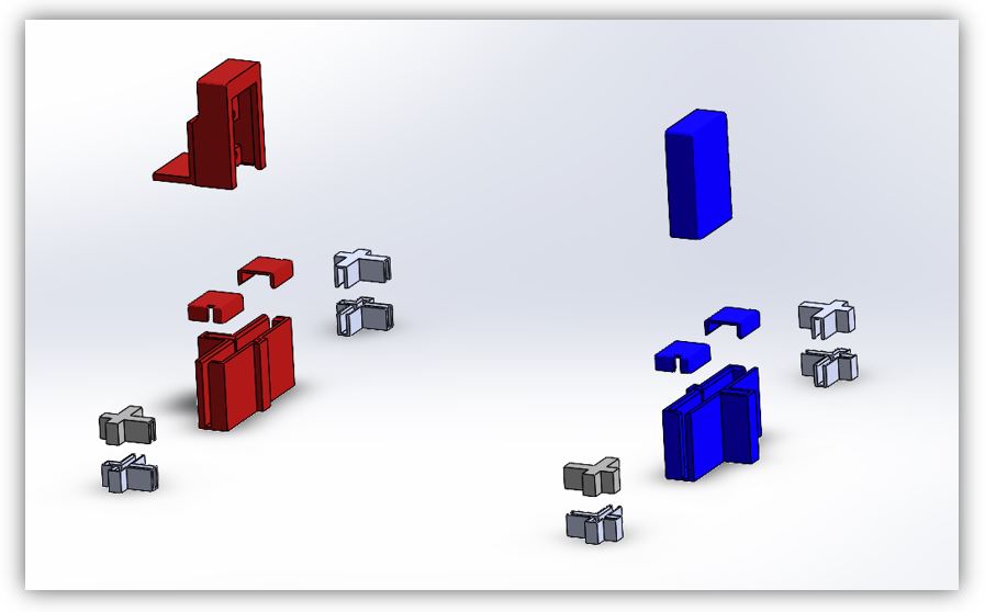
Assembling the reinforcements.
Visualization of the assembled reinforcements.
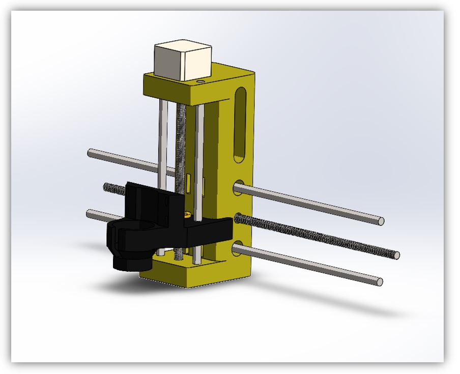
The carriage has the main body (yellow part) made in 3D printing. Likewise, the support part of the tool is also thermoplastic, by means of 3D printing.
Alignment of the carriage parts.
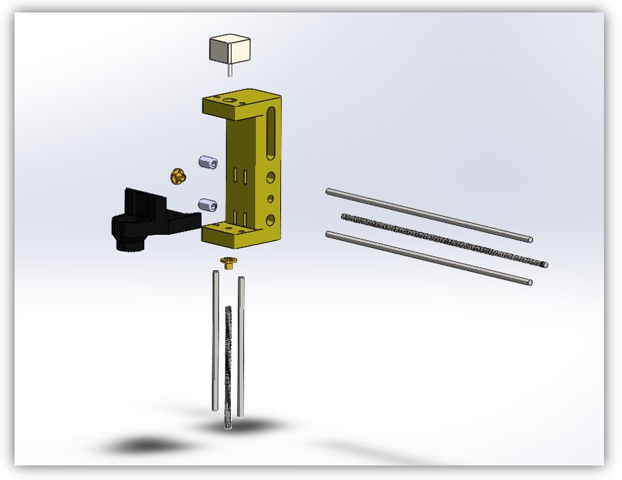
Assembling the carriage.
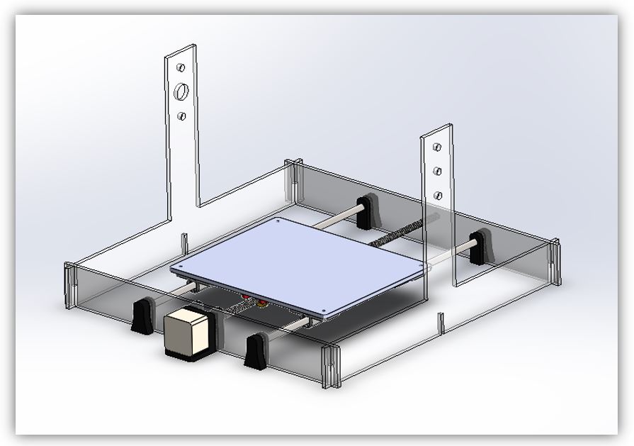
Exploded view of the work table, for milling.
Assembling the worktable.
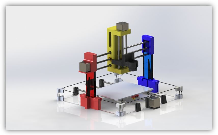
Strawberry Milling Machine Assembly.
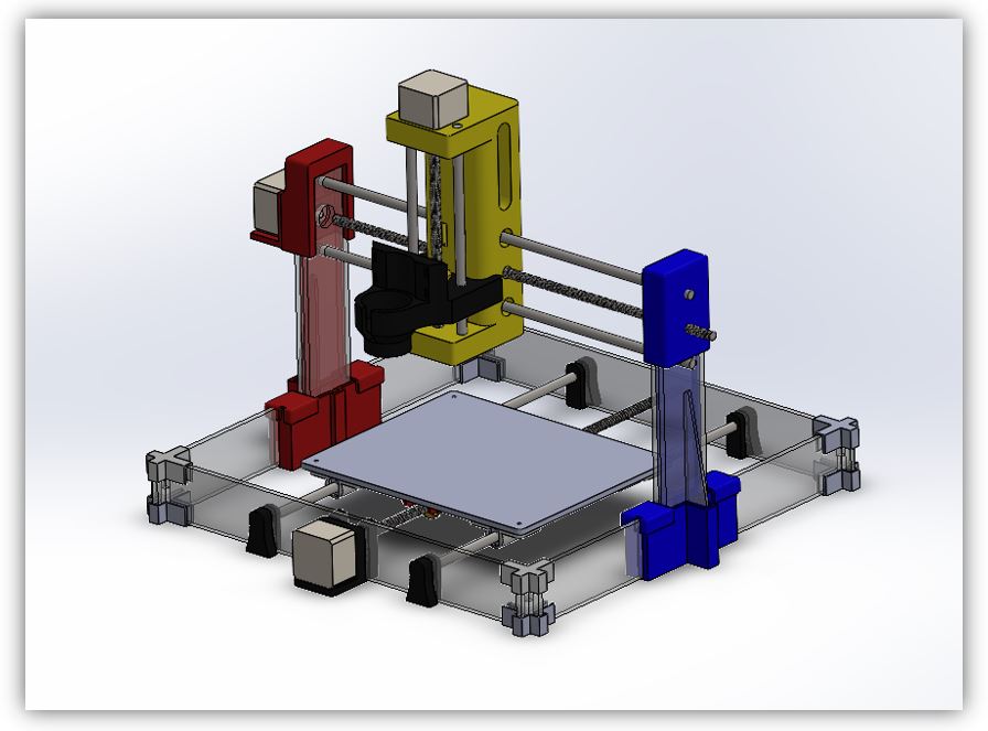
Render of Strawberry milling machine. To have a first look at the finish of the machine.
Electronics
For the electronics of the Strawberry milling machine you need:
■ 3 nema 17 motors
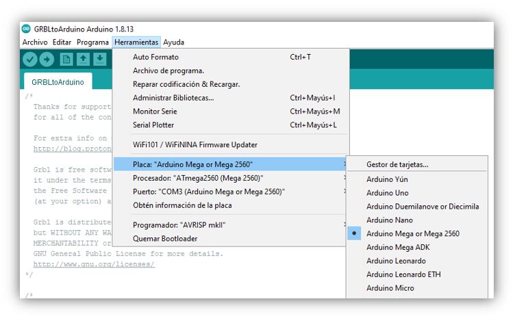
■ An Arduino Mega 2560 board
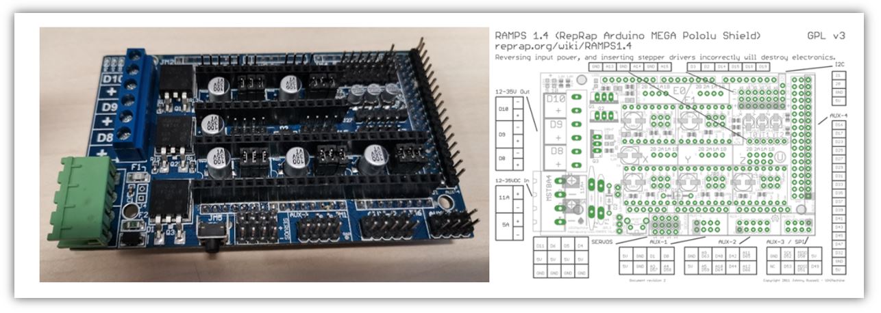
■ A Ramps 1.4 or 1.6 board
■ 3 Drivers A4988
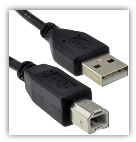
■ 1 USB cable (A to B)
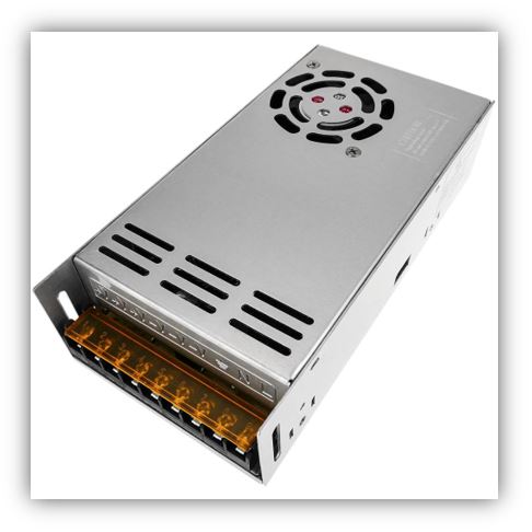
■ A 12V Source
Arduino Mega 2560 Rev3
The Arduino Mega 2560 is a development board based on the ATmega2560 microcontroller. It has 54 digital inputs / outputs (of which 15 can be used as PWM outputs), 16 analog inputs, 4 UARTs, a 16Mhz crystal, USB connection, DC power jack, ICSP connector, and a reset button.
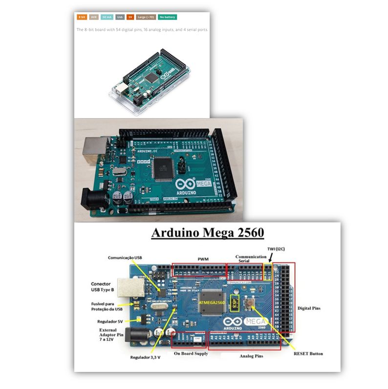
Arduino Mega link https://store.arduino.cc/arduino-mega-2560-rev3 and Arduino Mega schematic: https://www.arduino.cc/en/uploads/Main/arduino-mega2560-schematic.pdf
RAMPS
The RAMPS “Raprap Arduino Mega Pololu Shield” are shields for Arduino MEGA designed to control stepper motors, generally NEMA, using POLOLU A4988 or DVR8825 drivers. They are widely used to control 3d printers, since in addition to stepper motors, we can manage all the peripherals that usually make up printers: fans, limit switches, power sockets, LCD screen. In our case we will only use it to control stepper motors. I have tried two models of Ramps, initially I started with the Ramps 1.6 but could not program it, so I used the Ramps 1.5 which did work for me. The design of RAMPS 1.5 is practically identical to that of RAMPS 1.4 (https://reprap.org/wiki/RAMPS_1.4)
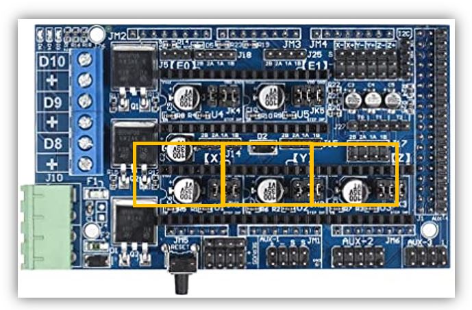
Board and Wiring guide
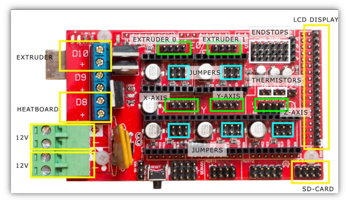
In the following diagram we see the connection guide.
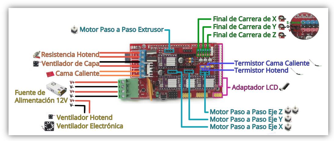
We will connect the 12 Vdc power supply, the 3 motors for the X, Y, Z axis.
Nema 17 stepper motors
We use three NEMA 17 motors. The Nema 17s have 200 steps per turn in principle. This means that with each step we obtain a movement of 1.8º per step.
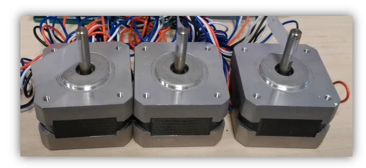
Nema 17 datasheet link (X17-1003LQCEF) http://silnikikrokowe.pl/SX.pdf
Drivers DRV8825
The DRV8825 is a stepper motor driver board that has on a DRV8825_chip that allows control of stepper motors through arduino type programming software and firmware. The DRV8825 board can supply up to 2.5-A peak or 1.75-A RMS output current (with suitable 24V 25 ° C heat sink).
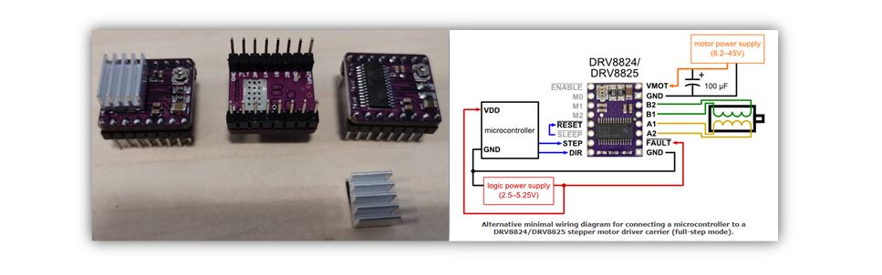
Enlace del datasheet DRV8825:
drv8825.pdf
Enlaces de descripción
REPRAP DRV8825
POLOLU DRV8825
12 Vdc source
The power supply has the mission of converting the alternating voltage into a direct voltage. In our CNC, the power supply is in charge of transforming the current from the electrical network (220V50Hz) to direct current. It is a switching power supply. It has terminals for making the AC (L, N and GND) and DC connections (3 -V terminals and 3 + V terminals).
USB cable (A to B)
Cable with USB connectors Version 2.0 male (plug) type “A” to male (plug) type “B” of 5 pins, allows the connection between the Arduino Mega and the computer.
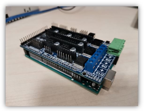
Connection of electronic components
First I attach the Ramp 1.5 on top of the Arduino mega 2560, be careful not to bend the pins of the Ramps, it must be attached carefully.
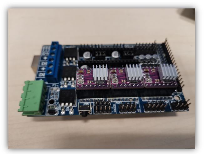
Couple the three DRV8825 drivers on Ramps 1.5
But we can use the jumpers that come with the RAMPS to work with microsteps, in which case we can achieve a ratio of 1/16 steps per turn in the case of A4988 drivers, that is, we can reach 3200 steps per turn. . And in the case of the DRV8225 we could reach 1/32, that is, 6400 steps per lap.
RAMPS 1.6 description link
REPRAP RAMPS 1.6
Datasheet and firmware link:
BIGTREETECH RAMPS 1.6
Programming, firmware and software
The process to work milling with the Strawberry milling machine is to choose the image or design that we want to mill and work it in Inkscape, to generate a vector file.
The image, we have to draw it in vector, in this case Inkscape is used to save the image in .ngc, which is the format understood by cnc through the Universal Gcode Sender software (this is a serial termination to communicate with the arduino and can make variations on the GRBL, which is the firmware that controls the machine). With the image created, it is loaded with the Universal Gcode Sender, configured and launched into the router bit, via a USB serial connection.
In order for it to work this way, the strawberry mill must first be programmed correctly, via firmware. To do this, the following sequence is followed.
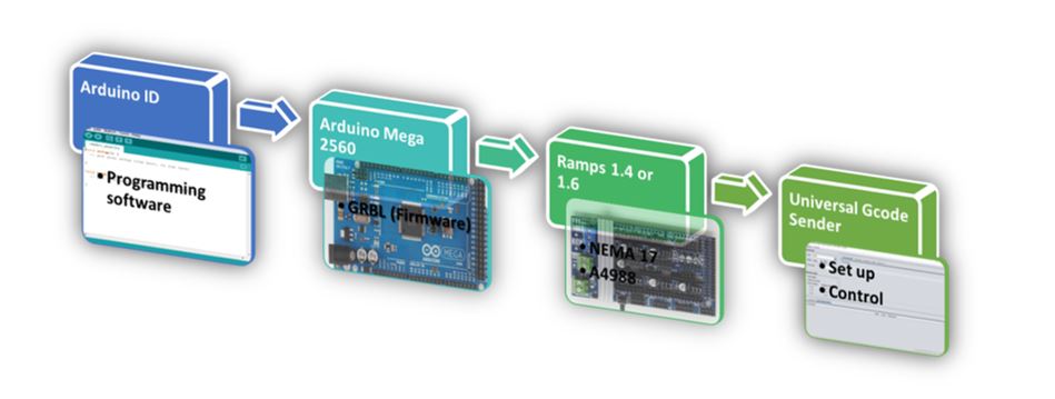
PROGRAM THE GRBL FIRMWARE WITH ARDUINO ID
NOTES:
■ Never connect the CNC Shield without having previously loaded the GRBL since it can burn, especially if the arduino has another program previously.
■ Universal Gcode Sender - It is shared development software; it can be found on GitHub.
■ GRBL Firmware - This is also a shared use firmware; it can be found on GitHub.
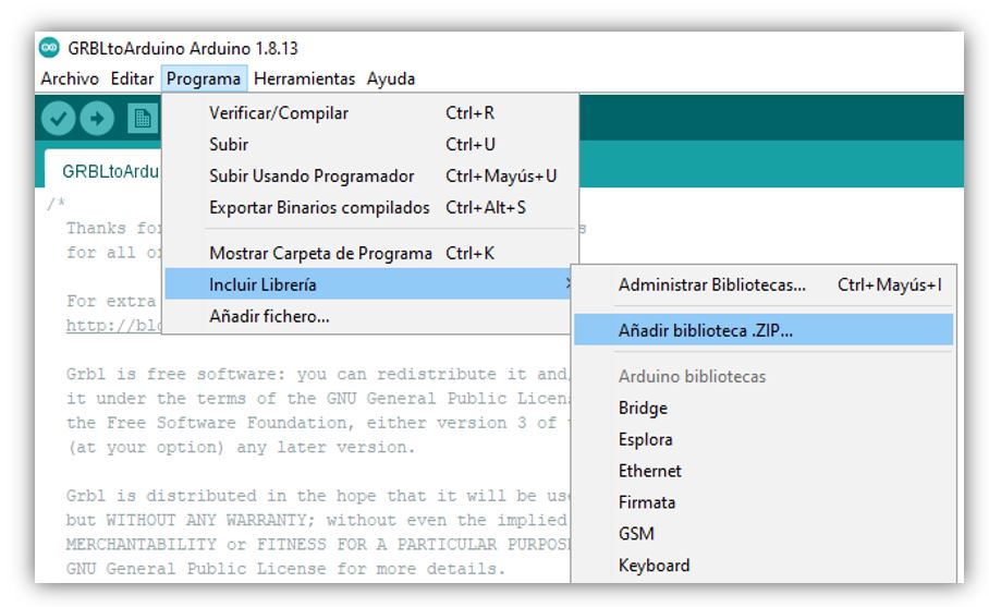
1. We connect the Arduino ID (free on the Arduino page, on any platform).
2. In the Program Menu -> Include .ZIP library -> add the path of the GRBL library.
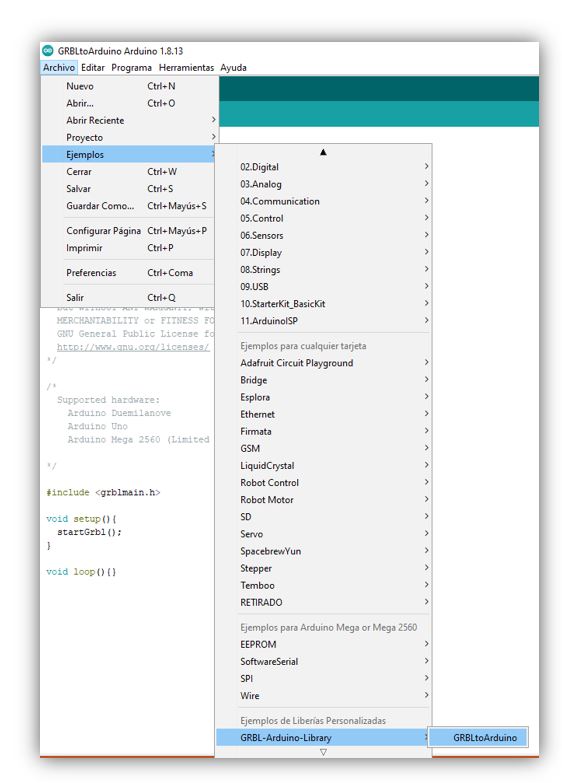
3. After File -> Examples -> find GRBL -> open the example there is. Basically what it does is copy the library on our Arduino. It comes prepared for Arduino Uno and Mega 2560. We upload it, it may take a little while because it is a bit heavy.
4. Now, what is needed is to configure it, for this we need a serial monitor, which we can open from the Arduino ID. We open the monitor and set the serial port speed to 9600 bauds. It should show: (for the GRBL 0.8 verified with Arduino ID 1.6.7).
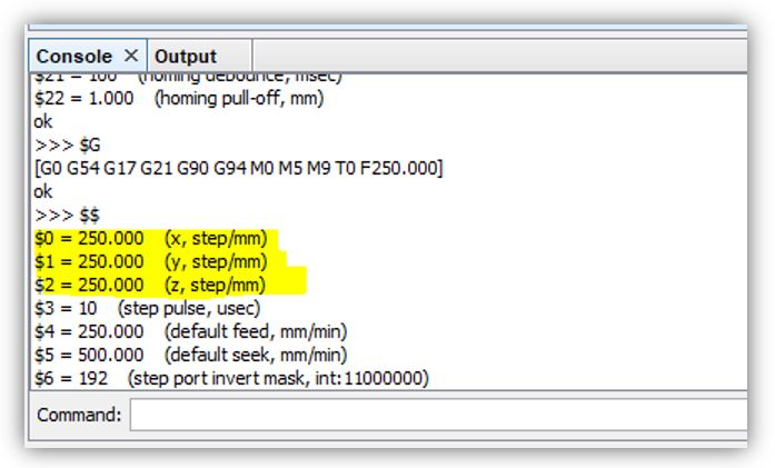
5. With the $ sign you can get help. We introduce $$ to generally configure the firmware. To change values, for the monitor put: $ item number = desired value. For example: change the heat of item 9 to 200 (instead of the 25 that were already on). Press enter to verify.
6. With $$ I can check that it has been changed.
7. These 22 parameters can be configured with other types of monitors in a simpler way, such as the Universal Gcode Sender.
8. Compile the program.
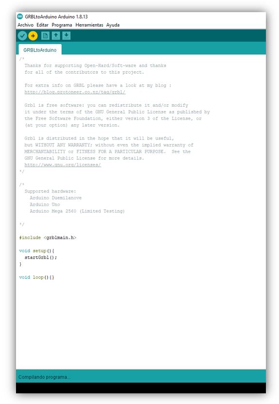
Warning: Problem that occurred in our case
I have compiled the program, but it does not move the motors, so we use another
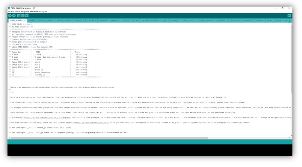
GRBL_RAMPS1_4 Library
that Álvaro Macian uses in the Fabacademy 2020 and that does work for us.
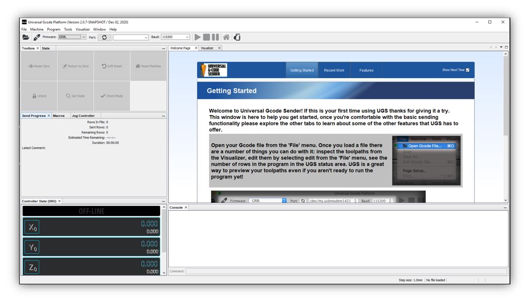
UNIVERSAL GCODE SENDER
What is universal G Code Sender?
For those who want to start in the world of CNC, this is one of the best options, through the user interface developed in Java and completely intuitive "UGS" manages to put in your hands a complete CNC control system, all this at the same time. one-click reach.
A full-featured gcode platform used to interface with advanced CNC controllers such as GRBL, TinyG, g2core, and Smoothieware. Universal Gcode Sender is a standalone Java application that includes all external dependencies and can be used on most computers running Windows, MacOSX, or Linux.
To run it you need to have JAVA installed.
We decided to give the GRBL firmware a try because it is easy to configure and can be controlled using the Universal G Code Sender software.
GRBL: The GRBL firmware is a key piece in charge of transforming the GCODE file into motor movement and is used in a great variety of CNC machines such as routers, laser engravers and a long etc.
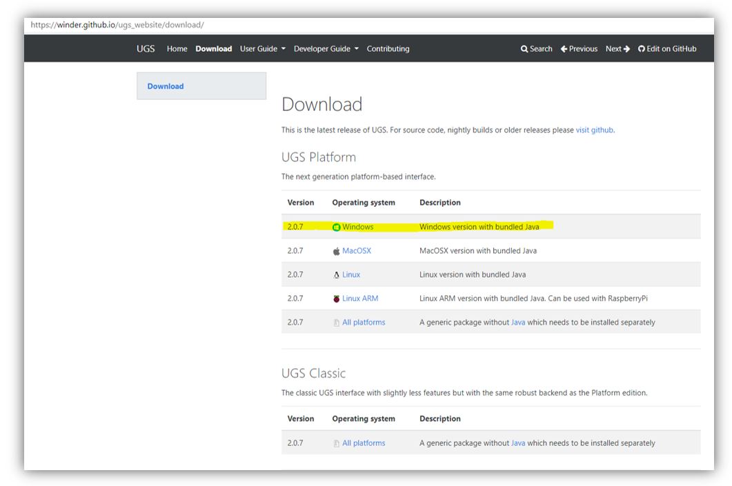
I download the GRBL firmware for Arduino
GRBL firmware
Follow the youtube manual “elprofegarcia” [link]
1. Unzip the ZIP files.
2. Open the .jar file. (1.0.8 tested version)
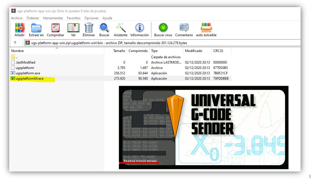
Note: other option, portable version, we used this option: Open the file ugs-platform-app-win.zip and select "ugsplatform64.exe"
3. With this console, you can create macros, you can control the machine directly, you can search for a file (such as a picture) and send it. To configure it, it is done from Commands.
4. Connect so that Commands can be activated. To do this, refresh the ports at a speed of 9600 baud. Select the COM that detects us. Select the GRLB firmware and open the port.
5. Now from commands, we can put $$, as with Arduino ID, and the GRBL configuration comes out. (the most important parameters in our case are those of the motors, x, y, z step / mm, steps to move one mm and that depend on the motor and the threaded rod, default feed, default seek). See in the manufacturer the degrees that each step takes, 360 between the degrees per step, and it gives us the steps of a complete turn, for the rod, see the mm that it travels per turn. If, for example, the (propeller) rod makes one turn in a distance of 8mm, it will be necessary to divide the steps for one turn of the motor, between these 8mm for the turn. In this way I will obtain the mm of displacement for my motor and my rod, this is set for the x, y, z step / mm. (with the one mm rods, it stays as is).
6. The parameter (step pulse, usec) with which we will indicate the pulse width that Arduino will recognize. (with 10 it works fine) ($ 3 = 10 (step pulse, usec).
7. Default feed is the speed with load, and the default seek speed when searching for some position. The two should be the same, or with a slightly less load. This must be seen according to the user; the manufacturer does not provide information.
8. If the motor vibrates or jumps, the speed is too high, the steps are wrong, or the pulse is wrong.
9. At a very high speed, steps may be lost so the milling result will be poor.
10. (step idle delay, msec) is the delay time, after placing an order. 15 usually works well.
11. (acceleration, mm / sec ^ 2) acceleration of the motors, depends on the motors being used. It is advisable to start from a value of 30 and go up progressively, in case you want to put more acceleration. (500 high speed motors)
12. The parameters (junction deviation, mm) (arc, mm / segment) (n arc correction, int) are used for plotting arcs and curves, with values of 0.050, 0.100 and 25 in this order, it works fine. Change if the curves do not work well, although they are valid for the layout of circuits.
13. (n-decimals, int) put it to 3 decimal places, so you gain a little more precision than with 2.
14. (report inches, bool) value 0 if we work in inches or set to 1 to work in mm.
15. (auto start, bool) if it is set to 0, the Arduino must be programmed to start, while with a value of 1 it starts automatically.
16. (invert step enable, bool) in case other drivers other than A4988 are used and it is necessary.
17. (hard limits, bool) useful when using limit switches to stop the machine when it reaches the limits. Enable 1. Since this way when giving auto-home, it will look for the limit switches. With a value of 0, the home must be found automatically.
Example: Movement with a GCODE file
I have followed the following tutorial [link]
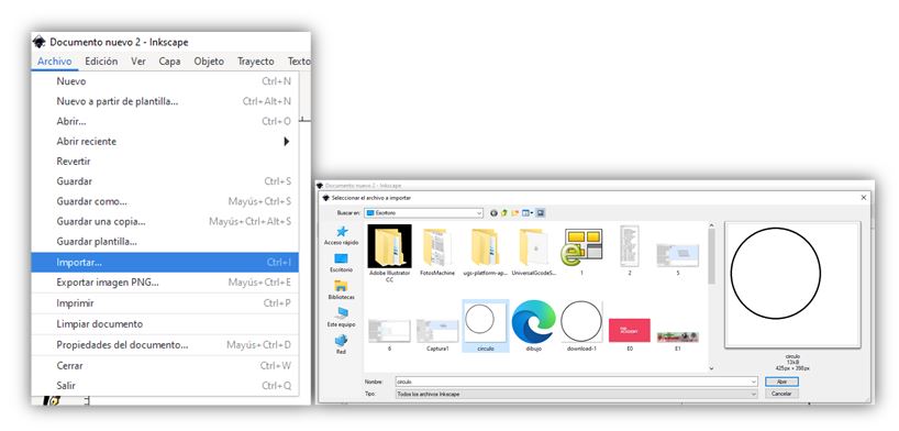
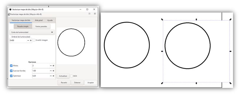
We use Inkscape to generate the gcode file. Open Inkscape and import the image. Initially we will do a test with a circle.
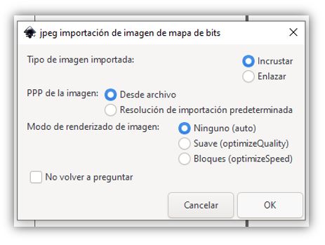
Leave the default parameters and click on "Ok"
Vectorize Bitmap
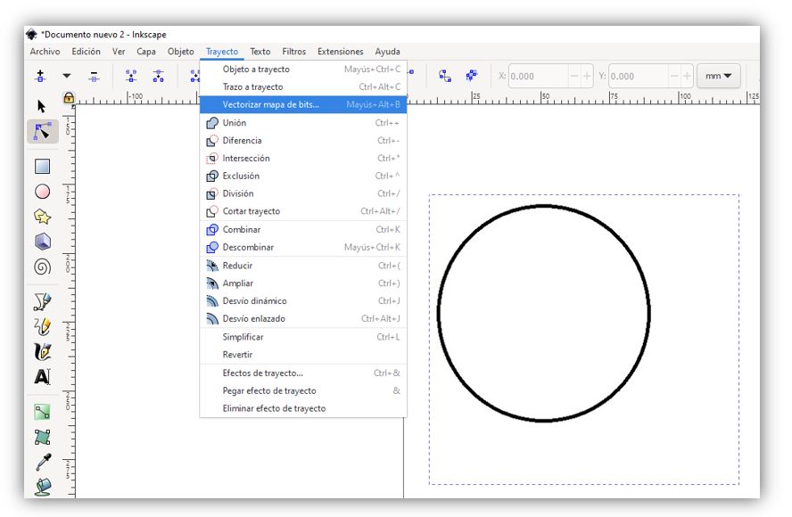
Select "OK" and another vectorized image will be generated. You must delete the non-vectorized image.
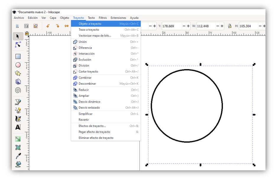
Select "Path / Object to path"
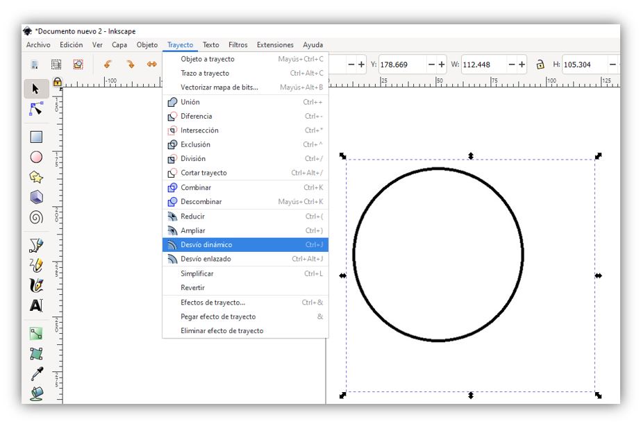
Select "Dynamic forwarding"
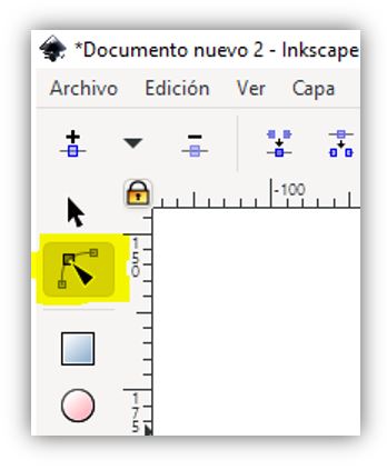
The following icon will be activated
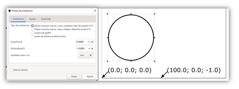
Select "Extensions / Gcodetools / Orientation Points"
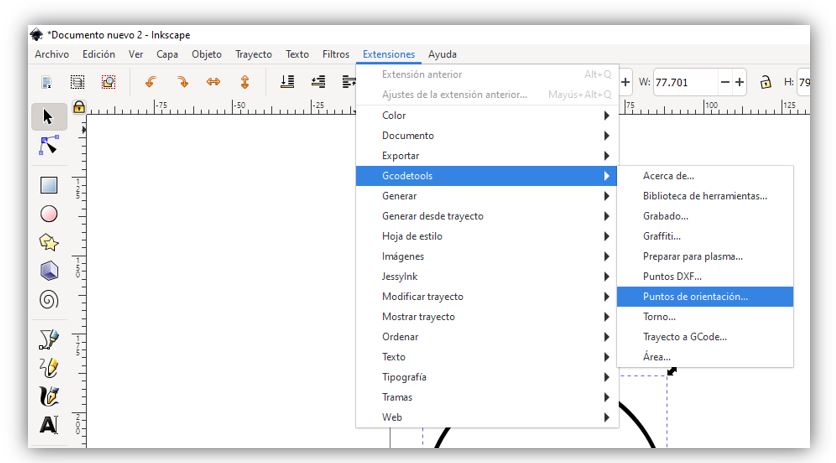
Click on "Apply"
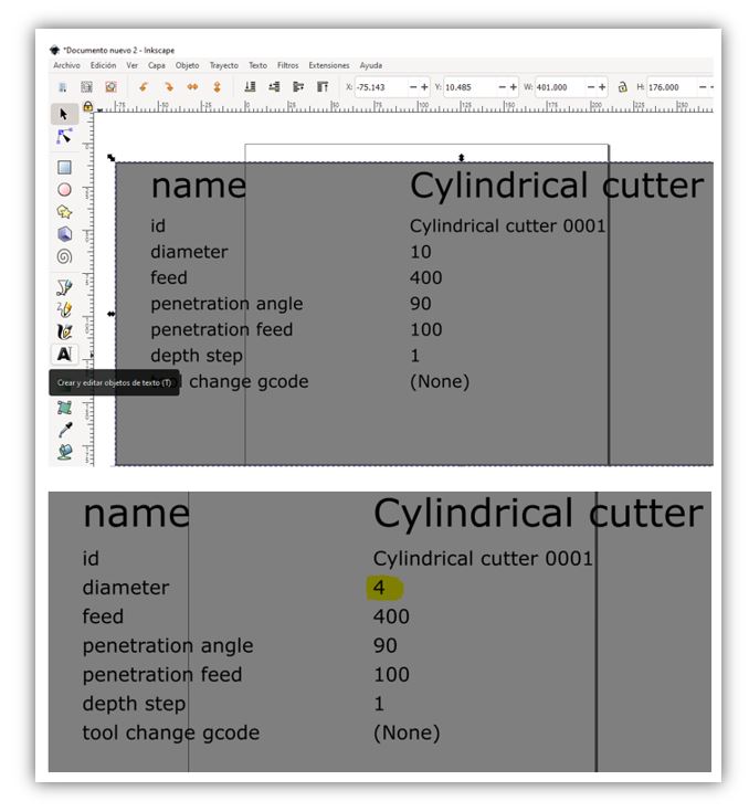
Select "Extensions / Gcodetools / Tool Library ..."
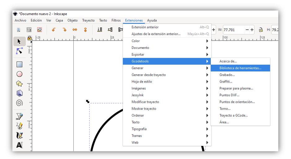
Select the "Cylinder" tool
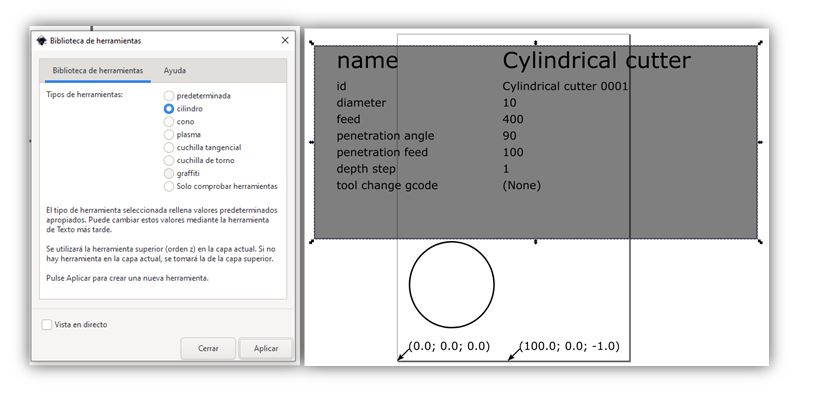
Change the parameters of the drill diameter “4mm”. Select the "Create and edit text objects" tool
Select the circle again with "Edit course notods or control handles (N)"
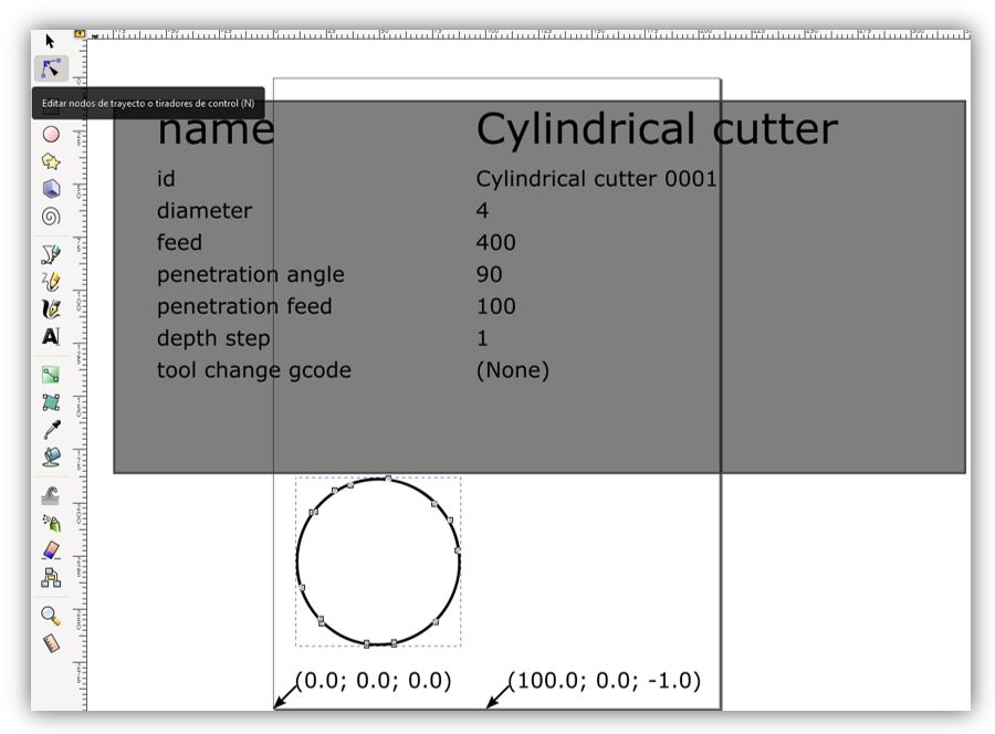
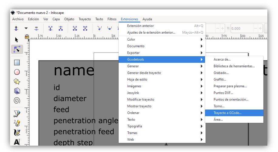
Select "Extensions / Gcodetools / Path to GCode ..."
Select "Preferences" and name the file and directory. Go back to "Path to GCode" and click on "Apply".
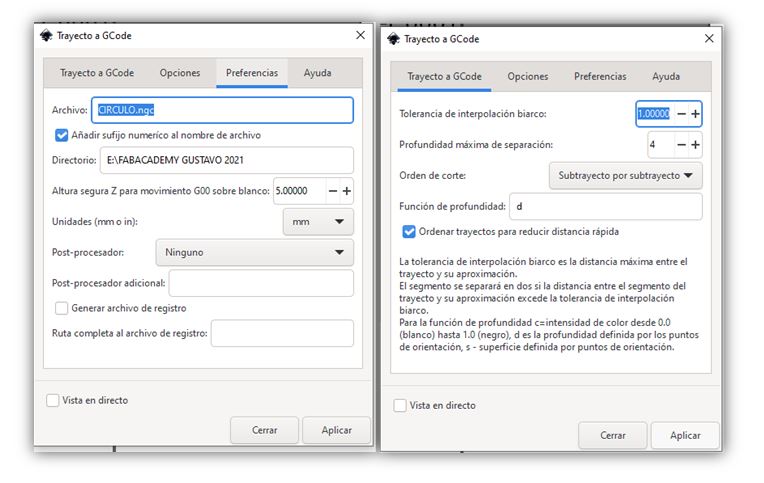
Arrows will appear with the trajectory of the Gcode.
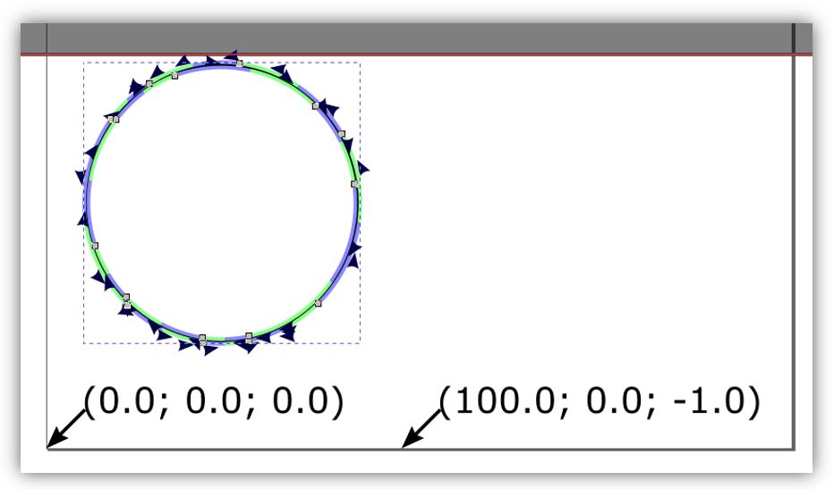
A ".ngc" file is generated.
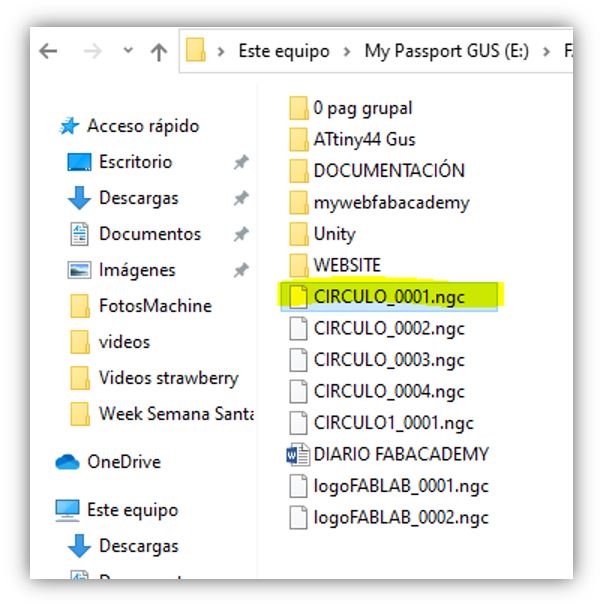
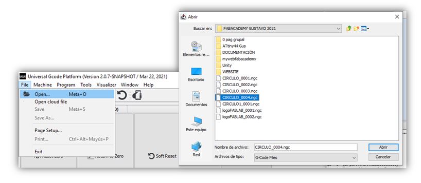
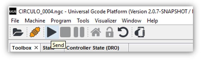
Open the UGS. Select "File / Open ..." and select the file ".ngc"
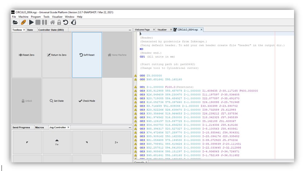
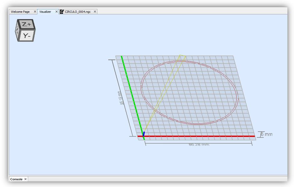
Click on "Play" to start the gcode path
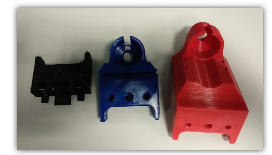
Updates
■ Strawberry Machine head shape update.
■ End of career to avoid collisions.
■ Use of the interchangeable head.
■ Manual levelling of the work table.
■ Automatic levelling of the work table.
■ Improvement of the reinforcement pillar in a single piece.
Files
Firmware and Programming
Project Universal G-Code Sender "Circle" (.ngc)
GRBL_RAMPS1_4 Library (Library)
GRBL_RAMPS1_4 Arduino Program (.ino)
3D models
Strawberry Milling Machine.rar
Strawberry Milling Machine Part1.rar