Electronics Design
Group Assignment 2021 (Héctor and Gustavo)
In this assignment, we have worked with the current and voltage measurements for the different components of the electronic board.
To make measurements of wattage, current, resistance, continuity, etc. We are going to use two electronic measurement tools: The multimeter and the oscilloscope.
Definition: "A multimeter or a multitester, also known as a VOM (volt-ohm-milliammeter), is an electronic measuring instrument that combines several measurement functions in one unit. A typical multimeter can measure voltage, current, and resistance. Analog multimeters use a microammeter with a moving pointer to display readings. Digital multimeters (DMM, DVOM) have a numeric display, and may also show a graphical bar representing the measured value. Digital multimeters have rendered analog multimeters obsolescent, because they are now lower cost, higher precision, and more physically robust."
Definition: "An oscilloscope, previously called an oscillograph, and informally known as a scope or o-scope, CRO (for cathode-ray oscilloscope), or DSO (for the more modern digital storage oscilloscope), is a type of electronic test instrument that graphically displays varying signal voltages, usually as a calibrated two-dimensional plot of one or more signals as a function of time. The displayed waveform can then be analyzed for properties such as amplitude, frequency, rise time, time interval, distortion, and others. Originally, calculation of these values required manually measuring the waveform against the scales built into the screen of the instrument. Modern digital instruments may calculate and display these properties directly."
Using a Multimeter:
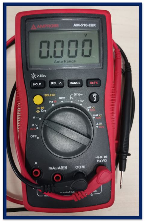
For this, we have used a polymeter.
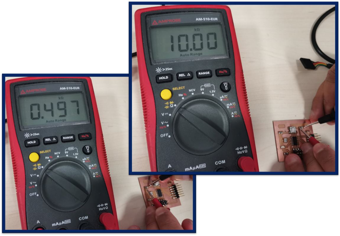
First, we have measured the values of the resistors to verify that their values match those of the manufacturer. In this case the 499 ohm resistor and the 10kohm resistor.
To measure the resistance, with this multimeter you have to put the wheel pointing to the Ohms symbol. To make it more comfortable to measure, we have set the automatic measurement range.
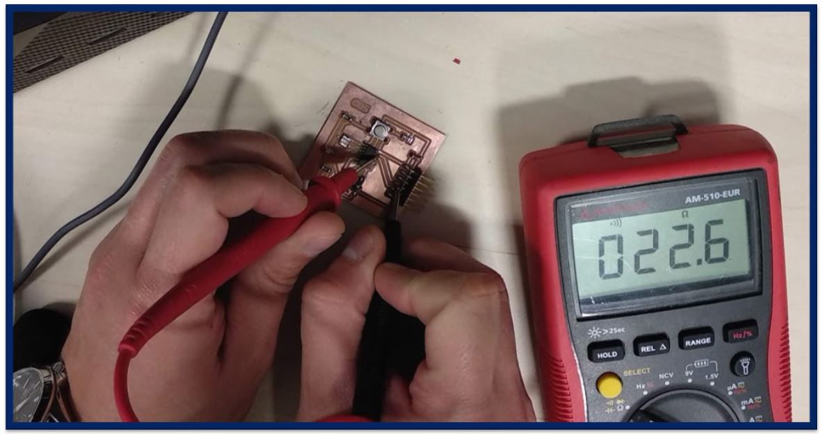
Later, we have measured continuity between the pins of the electronic components connected to each other.
Usually, when measuring continuity with the multimeter, the multimeter will beep.
To configure the continuity mode, you have to put the wheel in the same position as to measure resistors. Although you have to press the yellow button until the wave symbol appears on the screen.
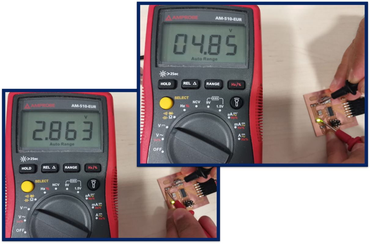
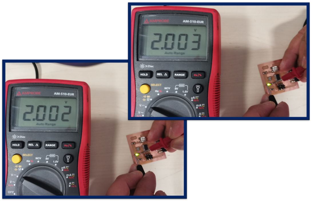
After checking these two things, we have measured the voltage values of different parts, to check how they are fed.
In the case of tension, we have to know which of them we are working with in order to select the correct one with the multimeter wheel. In this case, we are measuring direct current, the symbol is a "V" with a "__" and below it "---".
To measure current, change the position of the black probe and select the A symbol on the wheel.
*** WARNING: the current is measured in series, in order to measure it, the circuit should first be opened at the measurement point.
(In this case it does not make much sense, because it would have to be desoldered)
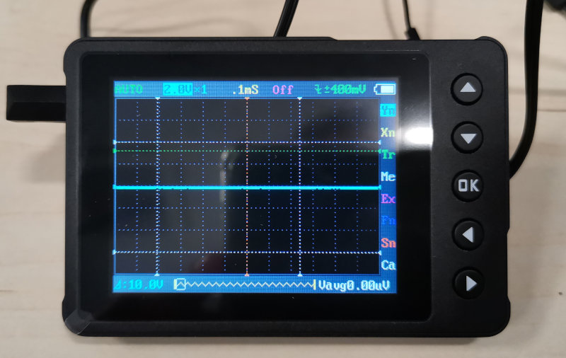
Using a Pocket Oscilloscope:
Also, with the same electronic board, we have tested some values with a portable (pocket) oscilloscope. It is a much simpler model than a laboratory one, but it has the advantage that it fits in a pocket. You can carry it like a mobile phone.
To show how it works, we are going to put the following video.
The measurement position is done in parallel, and the oscilloscope shows us the waveform of the 5V voltage for this case, showing that the led is powered and that is why it turns on.
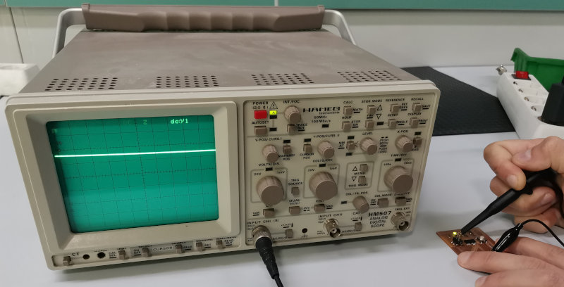
Using a HAMEG Oscilloscope:
We have used the HAMEG HM507 oscilloscope to measure the voltage of the helloboard.
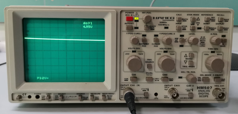
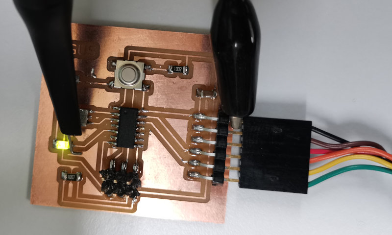
Connecting a clamp to the 5v signal of the led pin and the other clamp to Gnd of the circuit. The value shown by the oscilloscope is 5.02Vdc
The help of new technologies
As a curiosity and help, we are going to show a couple of applications that may be useful. They are for Android and they are free:
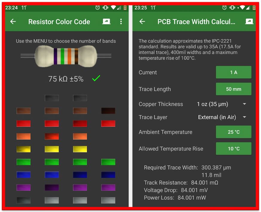
The first one is called: Electrodoc
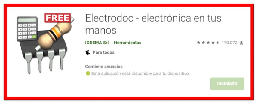
It is a library for electronic components, component calculator, symbol consultation, etc.
An example can be to consult the color codes of the resistors to know their value (left image). Or, know a track width for our electronic board based on the current data, the length of the traces, the thickness of the copper, the temperature ... (image on the right)
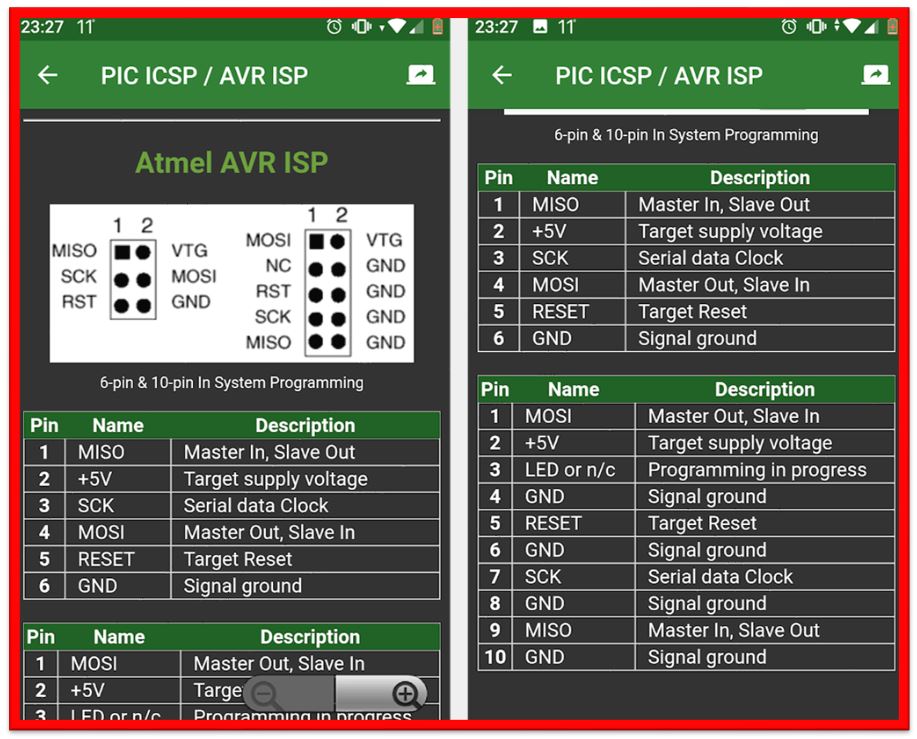
In our case we can also check the configuration of the pins of the Attiny, or of Arduino if someone uses it.
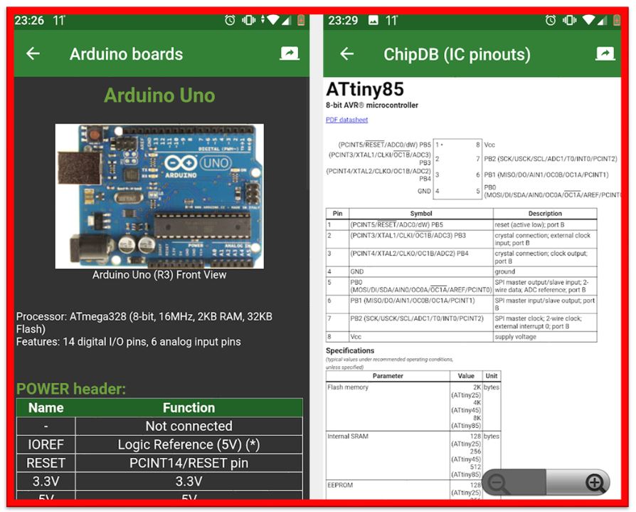
In addition, we can also consult the configuration of the power and programming pins (ISP)