Networking and Communications
Group Assignment 2021
1. I2C Communication of boards
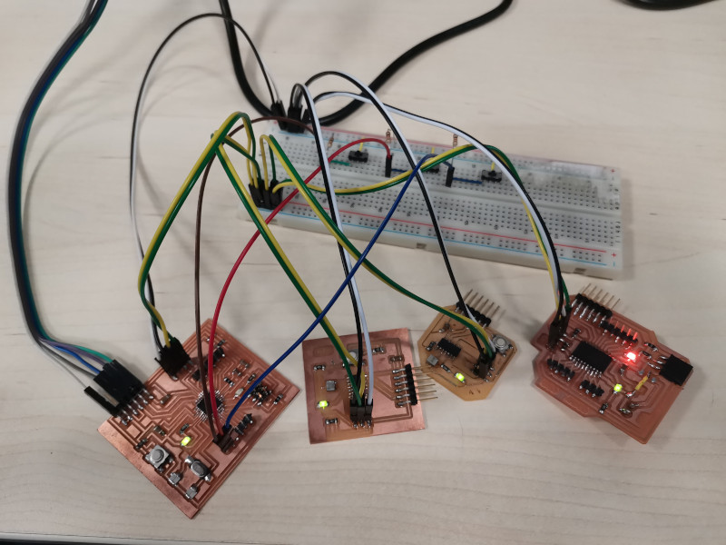
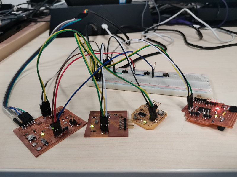
I am going to use the I2C communication protocol to communicate 4 boards, a Master (MyBoard ATmega328p) and 3 slaves (HelloBoard ATtiny44, HelloBoard ATtiny44 and Myboard ATtiny3216).
1.1 Master and Slave1 / Slave2 / Slave3 - 3 Switch
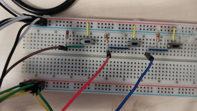
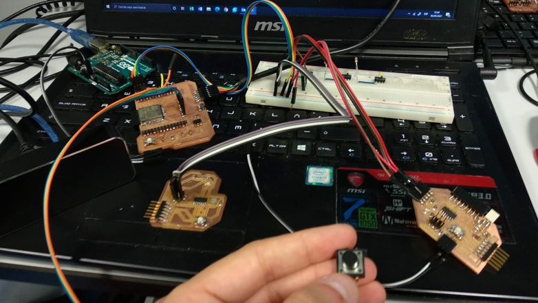
I connect the Master and the three Slaves. The communication for the three Slaves is enabled by three switches that will enable the independent I2C communication of each Slave.
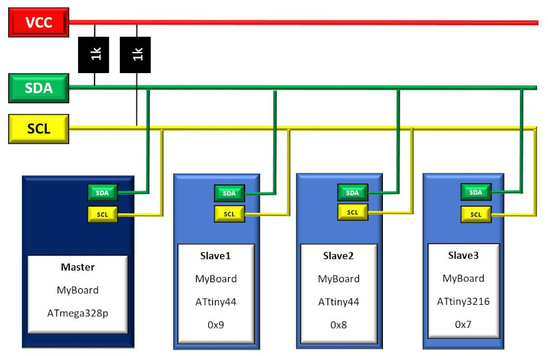
In the I2C communication configuration, it is essential that the slaves have different addresses:
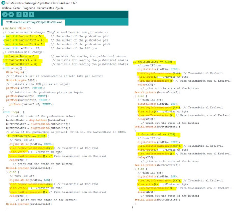
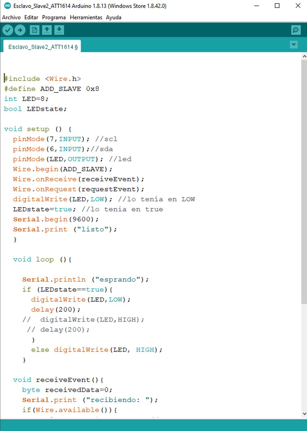
Slave1 = 0x9, Slave2 = 0x8 and Slave3 = 0x7.
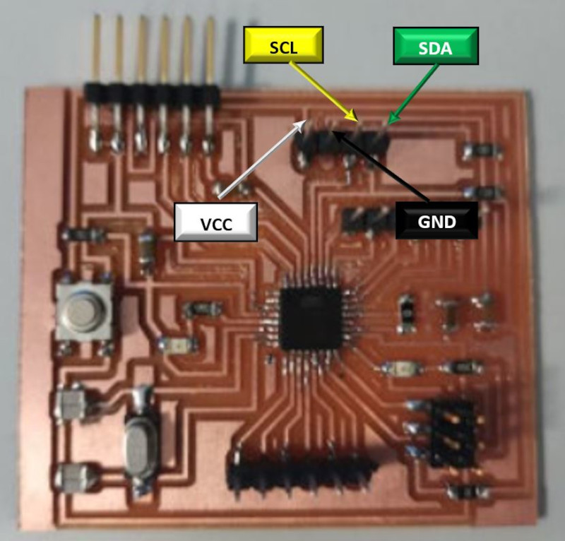
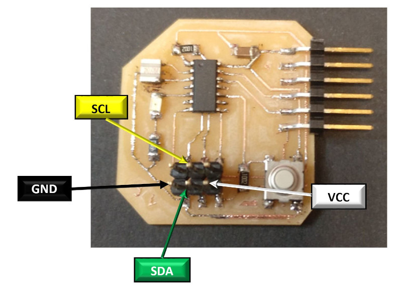
We use the ATmega328 as a master, the 4 pins of the board are connected (SDA, SCL, VCC and GND).
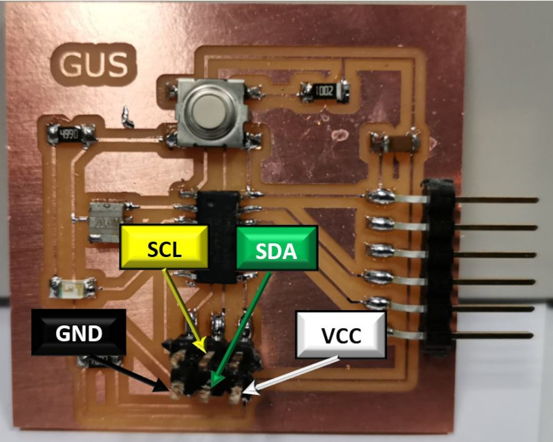
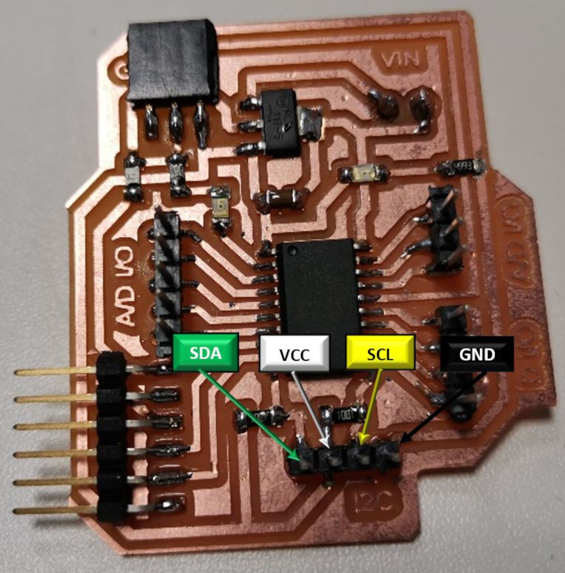
For the slaves we use the ATtiny44, ATtiny3216 boards. We connect the pins equally (SDA, SCL, VCC and GND).
- Switch1 OFF: Master Led off and Slave1 led On.
- Switch1 ON: Master LED on and Slave1 LED flashing.
- Switch2 OFF: Master Led off and Slave2 led On.
- Switch2 ON: Master LED on and Slave2 LED flashing.
- Switch3 OFF: Master Led off and Slave3 led On.
- Switch3 ON: Master LED on and Slave3 LED flashing.
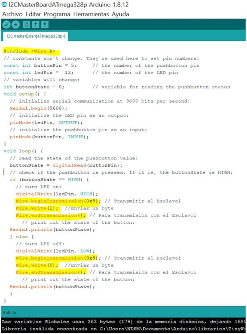
I use the Wire.h library to configure the Master's I2C communication. The program works with a switch button that in HIGH activates the I2C connection and starts the transmission with slave1 (0x9) sending it a byte (1) and in LOW it sends another byte (0).
I create another program so that the master can communicate with 3 slaves, I identify the slave1 (0x9), slave2(0x8) and the slave3 (0x7). Using only one button to enable communication.
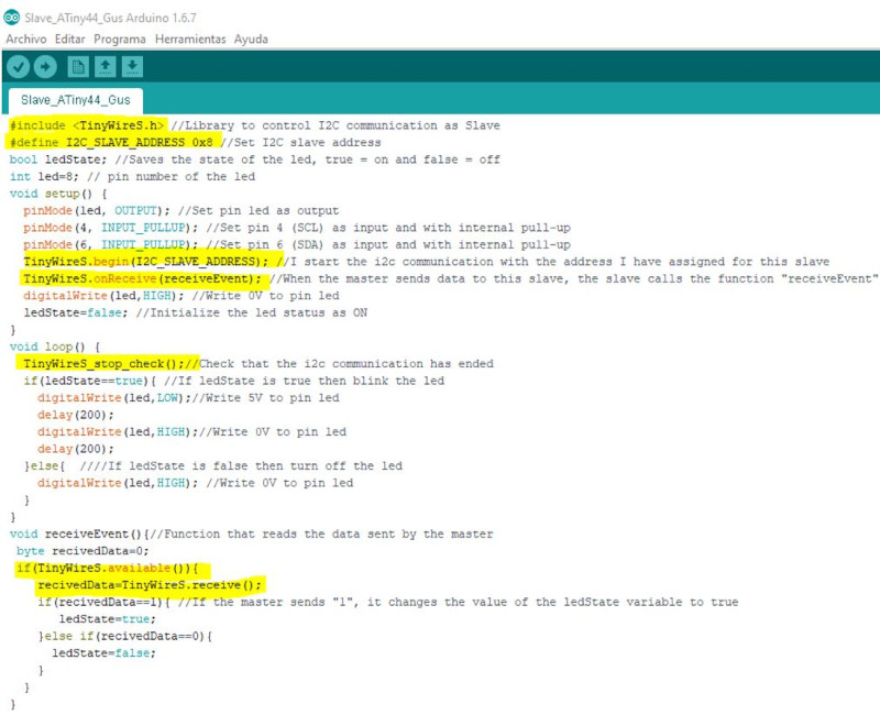
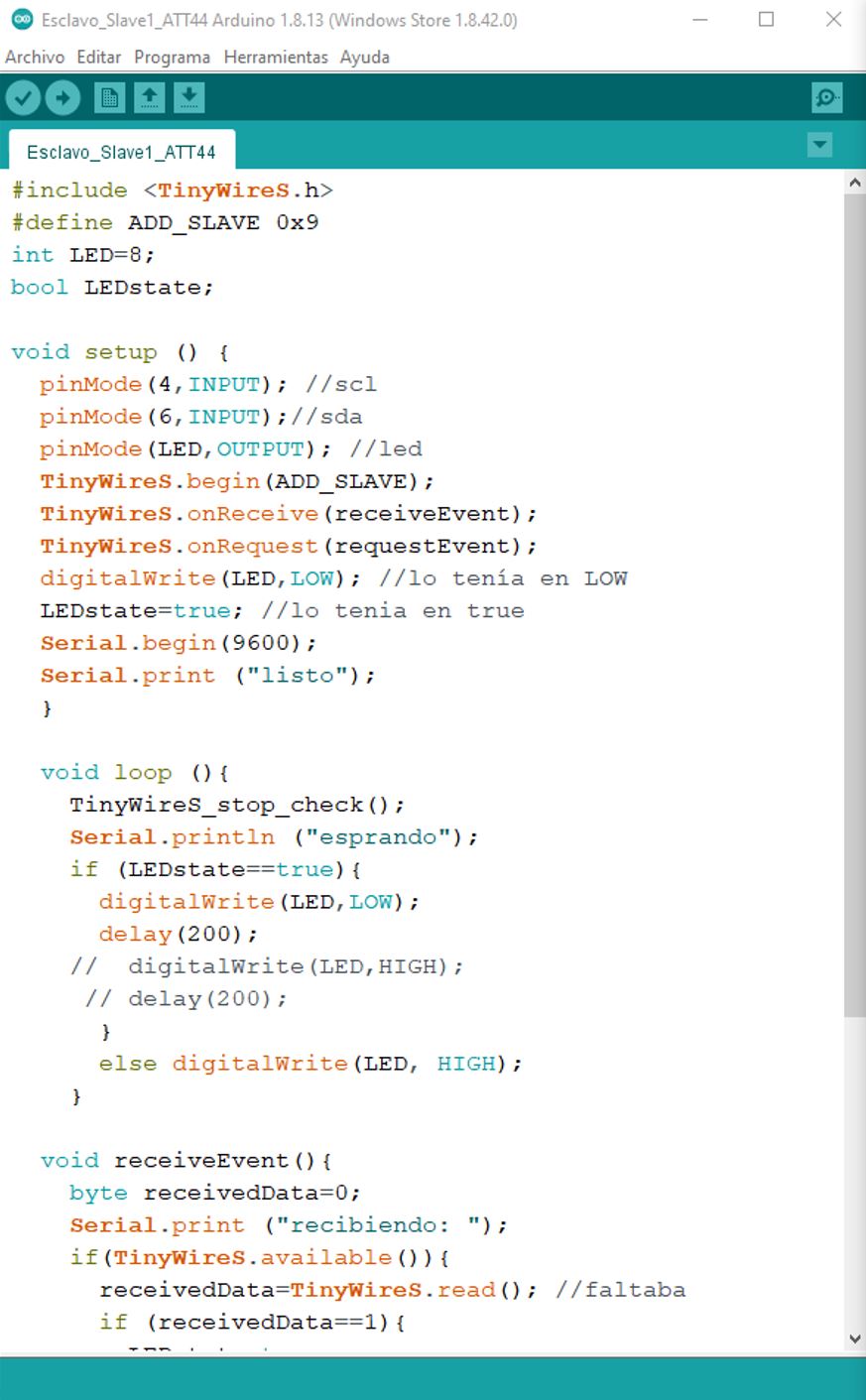
Slave 1 and Slave 2 programming use ATtiny44, I just have to change the address: I2C_SLAVE_ADDRES 0X9 for Slave1 and I2C_SLAVE_ADDRES 0X8 for Slave2.
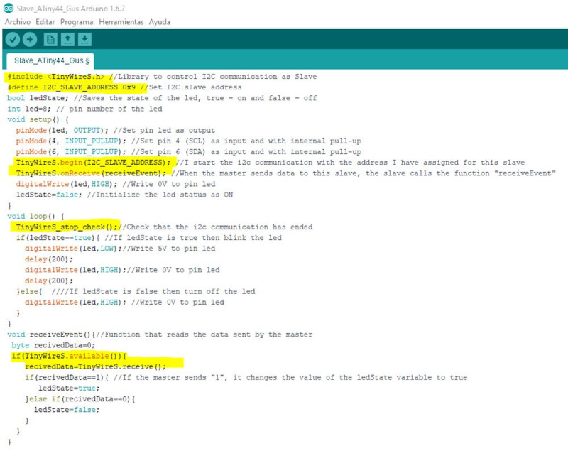
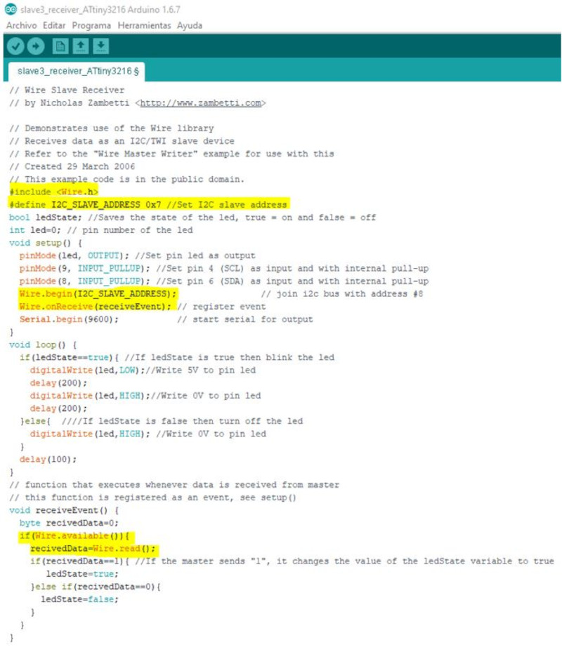
Slave 3 programming use ATtiny3216, I just have to change the address: I2C_SLAVE_ADDRES 0X7
Files:
Program Master ATmega328p
Program Slave_ATtiny44
Program Slave_ATtiny3216
2. Example with the three circuits: 1 master and two slaves:
For this example, I used 3 electronic boards. The master board with the ESP32 and the slaves with the Attiny44 and another with the Atiny1614.
The master electronic board is that of the ESP32 microcontroller, which uses the I2C to communicate with the other boards using pins 21 - SDA, 22 - SCL, GND and VCC.
The two slave electronic boards are that of the ATtiny44 microcontroller that uses pin 4 - SCL, pin 6 - SDA, GND and VCC for the I2C bus and that of the ATtiny1614 microcontroller with pins 6 - SDA, 7 - SCL, GND and VCC for I2C communication between electronic boards.
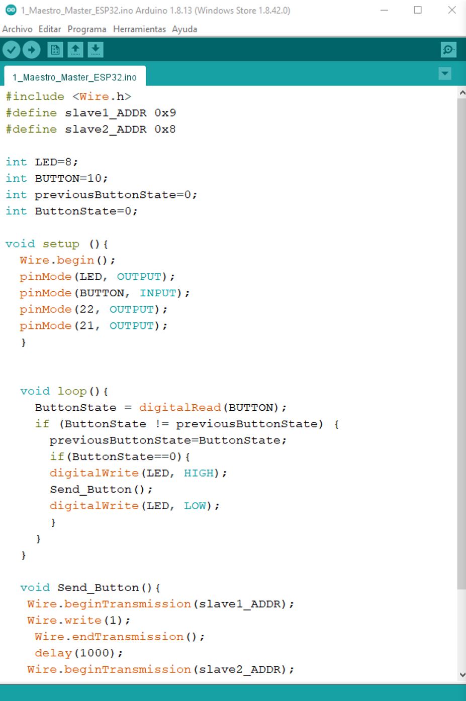
The master code makes that through a button, connected to the master board (ESP32), it sends a signal to the board with the Attiny44 that turns on a led for 3 seconds and another signal to the Attiny1614 that turns on another led for 1 second.
The result can be seen in the video:
Summary of group work::
With the example of connectivity between 4 electronic boards and the example using 3 electronic boards, documented more extensively in the individual work, we believe that it is possible to make the combinations with all the boards shown.
You only have to adapt the pins of each code to the microcontrollers you want to use as a master or as a slave.