Input Devices
Group Assignment 2021 (Héctor and Gustavo)
Analog Input (POTENTIMETER)
A potentiometer is a type of variable resistor. Its main function is to reduce current flow by resisting it. The resistance of the potentiometer is graduated by turning it.
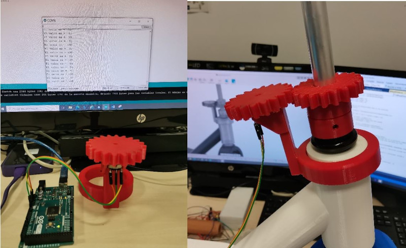
The final Project by Gustavo Salcedo (VR SCOOTER) uses a potentiometer to measure the turn of the direction of the handlebar of the electric scooter, we will take advantage of this assignement to take the data from the potentiometer and see the analog values.
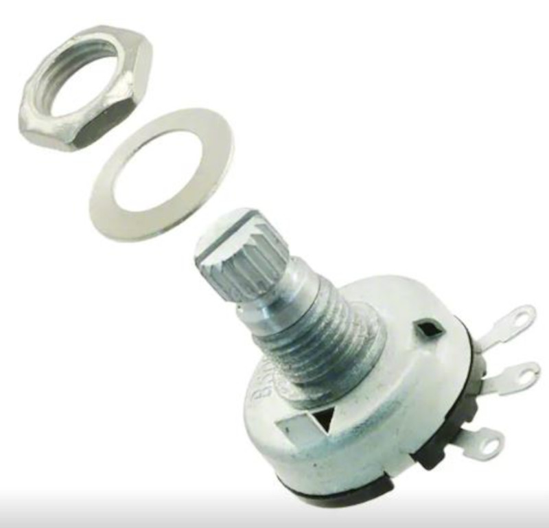
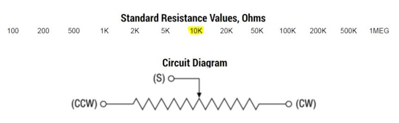
The Potentiometer that we will use is: (P170N-QC12BR10K) POT 10K OHM 1 / 10W PLASTIC LINEAR.
Potentimeter website
Potentimeter datasheet
I have followed this tutorial to make the potentiometer measurements.
Potentimeter tutorial
How to measure a potentiometer:
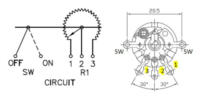
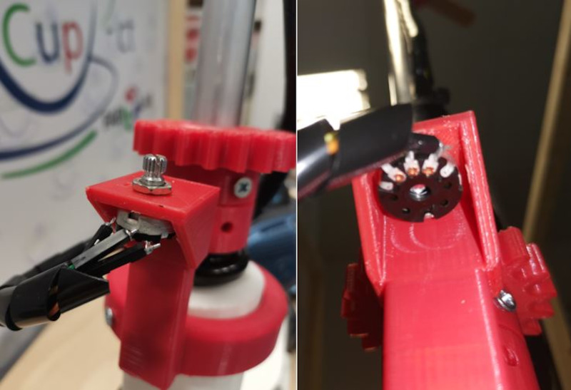
• Look closely at the potentiometer. Locate the three small tips or tabs that come out of it. Two of them are the "terminals", the ones that are usually next to each other, and the one that remains, located in a different place (in the middle), is the "variable terminal".
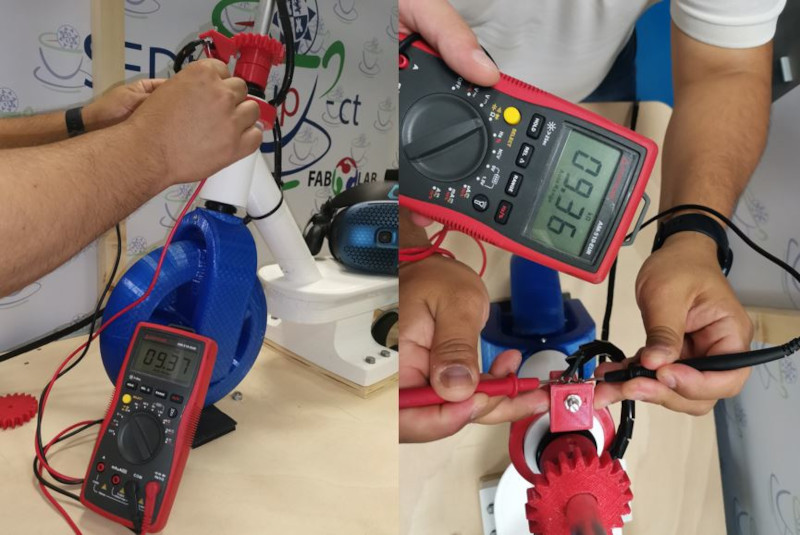
• Take the test leads from the ohmmeter. Put them on the potentiometer terminals. The reading that you are going to see will be very close to the nominal resistance value of the potentiometer. If the reading is too far from the nominal value, it is because you put one of the ohmmeter's test leads on the variable terminal of the potentiometer. The value displayed by the ohmmeter may not be the nominal value of the potentiometer. Typically, this class of devices has a tolerance of between 5% and 10%. Not all knobs reflect their tolerance, but the reading you get shouldn't be outside of that range. The datashhet value is 10kΩ and the value with the multimeter is 9.36Ω.
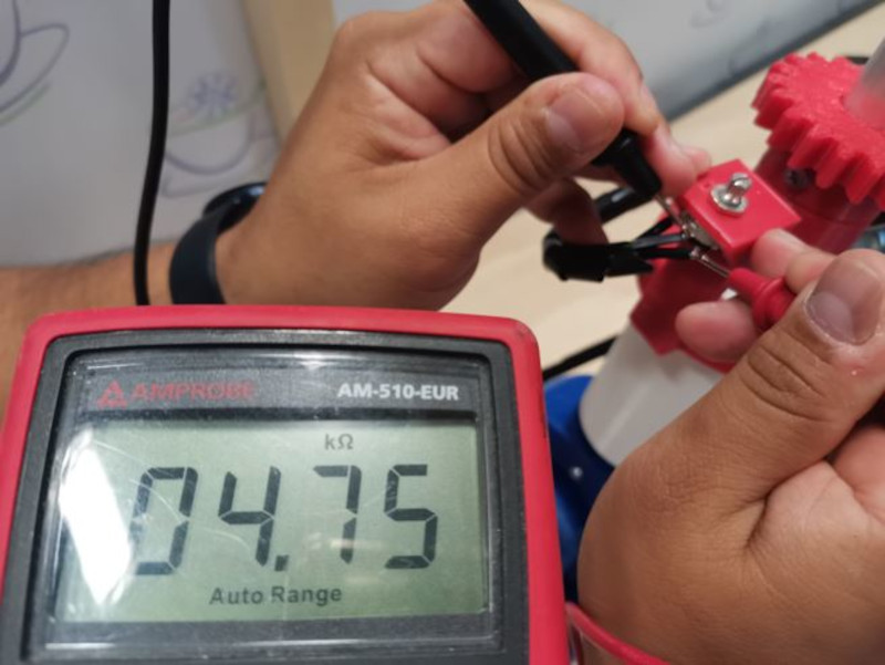
 • Take one of the test leads from the ohmmeter and put it on the variable terminal. Now you should turn the controller slowly and completely to the other side and keep your eyes on the ohm reading as you do so. The resistor should have a very small value at the beginning end and should have a maximum value close to the nominal value when you reach the end end. In addition, the increase in resistance when going from the initial end to the end must be slow and gradual, according to the rotation of the controller, without presenting sudden resistance jumps.
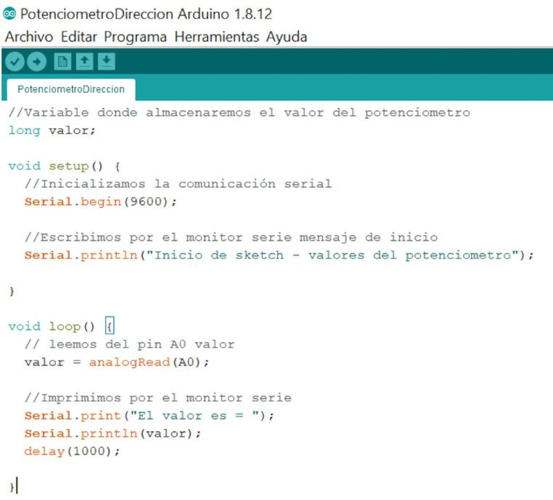
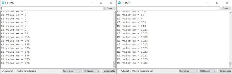
Arduino Potentiometer Program
I have followed these tutorials to read a potentiometer signal with Arduino:
https://programarfacil.com/blog/arduino-blog/el-potenciometro-y-arduino/
https://www.luisllamas.es/lectura-de-un-potenciometro-con-arduino/
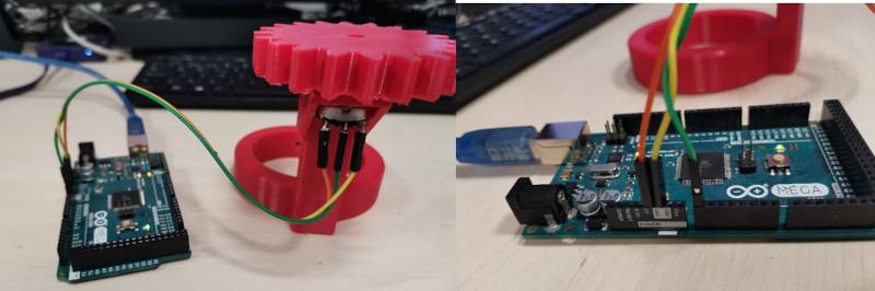
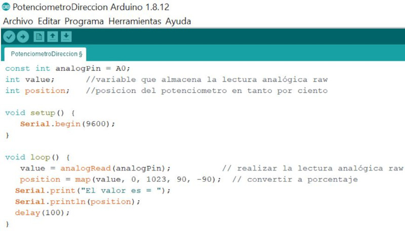
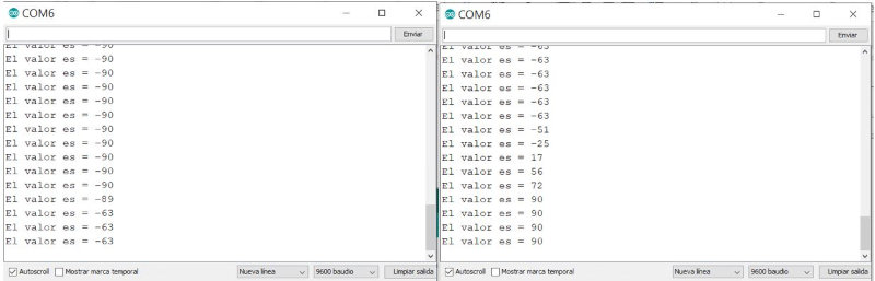
I have loaded another program that prints the values of angles between -90 and 90 degrees through the serial port.
Signal measurement with oscilloscope
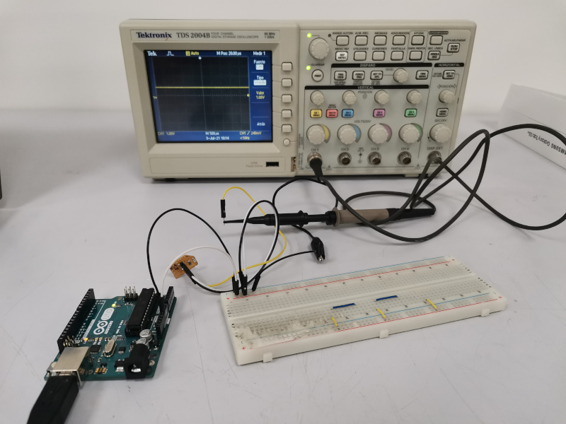
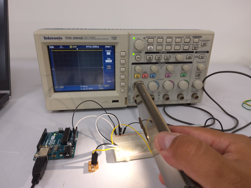
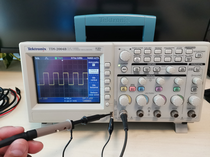
We have used the Tektronix TDS 2004B oscilloscope to measure the potentiometer signal. We first perform a test run on the signals from the oscilloscope itself.
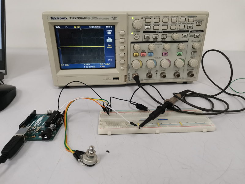
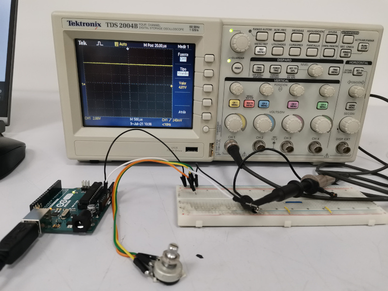
We use an arduino Uno to power a 5Vdc and Gnd circuit, connected to the two pins of the potentiometer to obtain the variable values of the voltage by turning the knob of the potentiometer increasing or decreasing the resistance of the circuit.
Using the oscilloscope probe, we connect the clamp to one pin of the potentiometer and the other alligator clip to the other pin of the potentiometer. The voltage signal is observed on the oscilloscope screen, which varies by turning the potentiometer knob from a value of 498 mv to 4.81 Volts.
Digital input (Sensor PT15 (Phototransistor)
Phototransistors are closely related electro-optical transducers that convert incident light into electrical current in applications such as position / presence sensing, light intensity measurement.
There are two versions of this phototransistor, the PT15 21B and the PT15 21C. I chose the PT15 21B. The 21B works in the invisible IR range .
Datasheet Sensor PT15

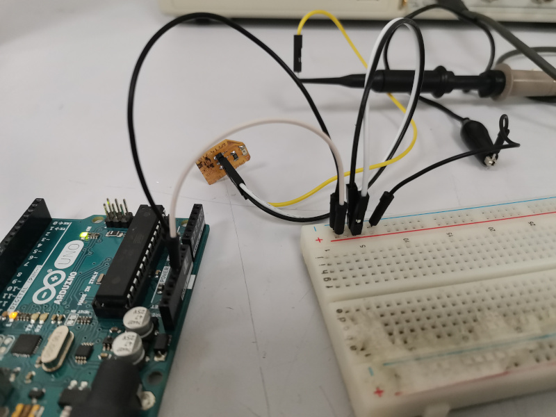
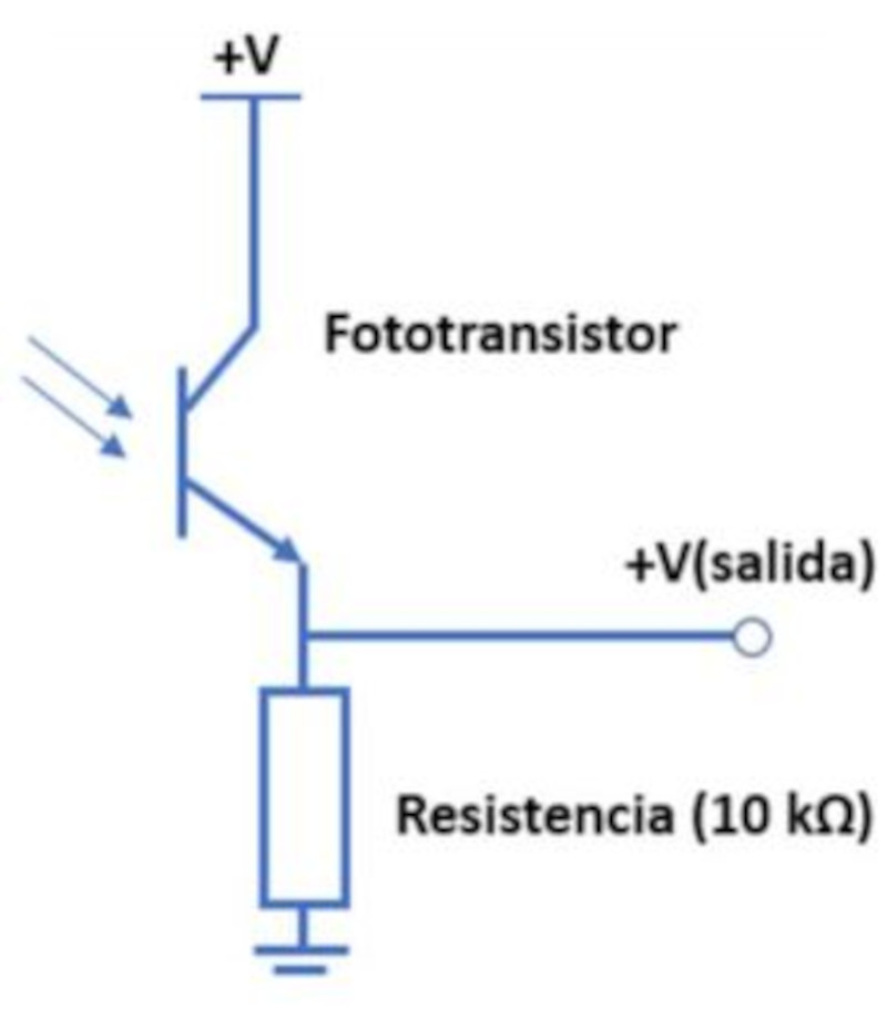
To connect the phototransistor to the board, a 10K resistor is necessary. The emisor is connected directly to VCC. The collector to the resistance and this node to the signal. The other side of the resistor to GND. As seen in the image.
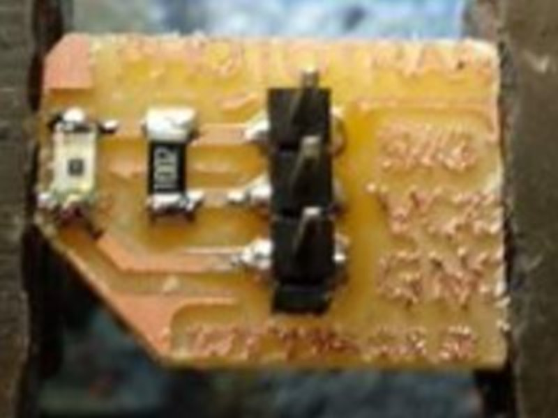
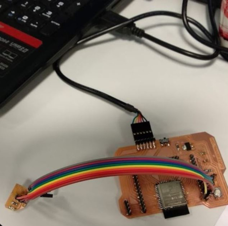
We used the sensor board and the ESP32 board that hector made this week.
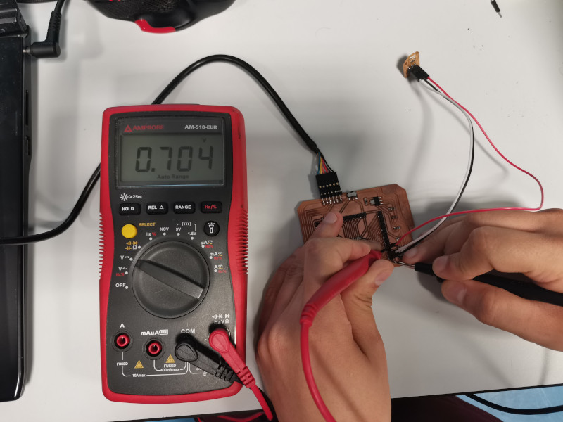
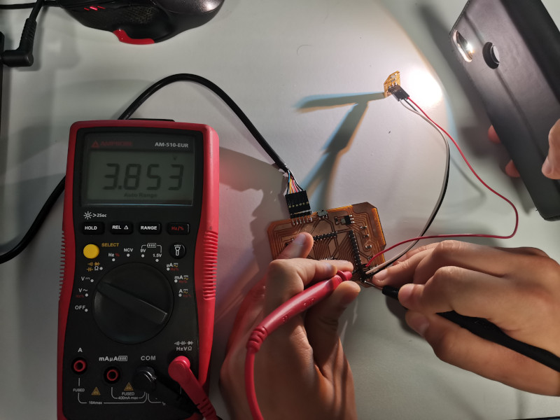
We connect the multimeter to the sensor input signal pins on the ESP32 board and measure the voltage values.
The value that the multimeter shows with the lab light is V = 0.704 volts.
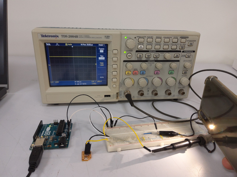
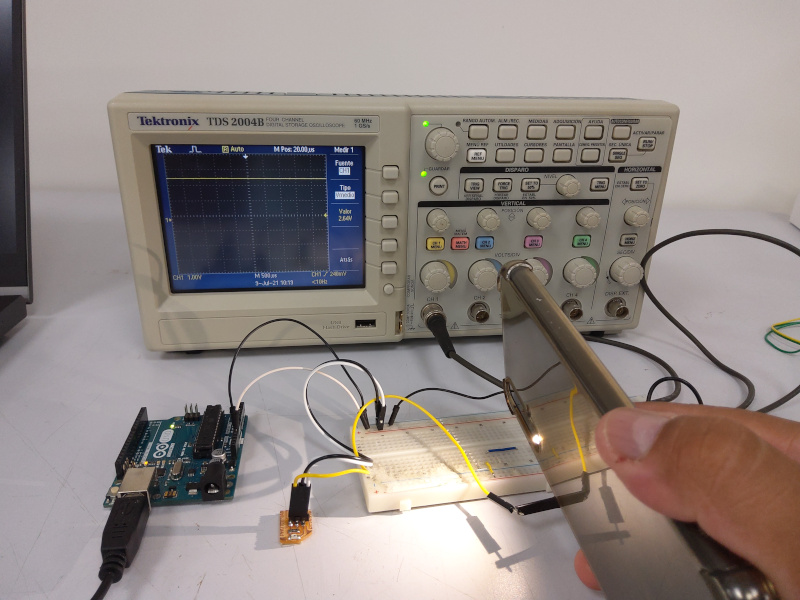
When we shine light with the flash of a mobile, the value increases progressively as the light source approaches. V = 3.853 volts.
Signal measurement with oscilloscope
We have used the same Tektronix TDS 2004B oscilloscope to measure the signal from the PT15 sensor.
We use an arduino Uno to power a 5Vdc and Gnd circuit, connected to the two sensor power pins (Vcc, Gnd).
Using the oscilloscope probe, we connect the clamp to a pin of the output signal (Signal) of the PT15 sensor and the other alligator clip to the Gnd pin of the PT15 sensor. It is observed on the oscilloscope screen that the voltage signal decreases when a light source is moved away (mobile flash) and increases when the light source is approached.