
WEEK 9
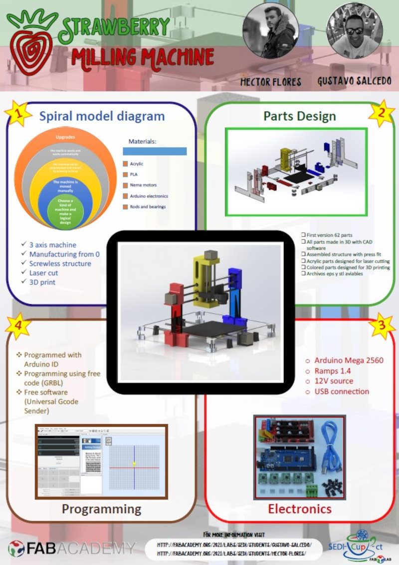
MECHANICAL DESIGN. MACHINE DESIGN
Group assignment: - design a machine that includes mechanism+actuation+automation, build the mechanical parts and operate it manually and document the group project.
Individual assignment: document the your individual contribution
1. Group assignment
You can see the complete documentation of the machine on our Sedicupct Group Website.
2. Individual Assignment: My contribution
The logo makes a little "joke" between the word "strawberry" and the "milling bit", which in Spanish are called the same, "strawberry", like fruit.
We have distributed tasks. Although we have both been present throughout the development, each one has focused on some tasks to work in parallel and save time.

2.1 Electronics
For the electronics of the Strawberry milling machine you need:.
- 1 Arduino Mega 2560 board.
- 1 Ramps 1.6 / 1.5 board.
- 3 stepper motors nema 17.
- 3 A4988 drivers.
- 1 12 Vdc power supply.
- 1 USB cable (A to B).
2.1.1 Arduino Mega 2560 Rev3
The Arduino Mega 2560 is a development board based on the ATmega2560 microcontroller. It has 54 digital inputs / outputs (of which 15 can be used as PWM outputs), 16 analog inputs, 4 UARTs, a 16Mhz crystal, USB connection, DC power jack, ICSP connector, and a reset button.

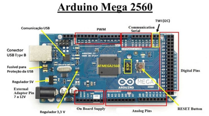
Arduino Mega link and Arduino Mega schematic: .
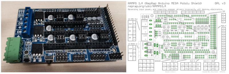
2.1.2 Ramps
The RAMPS “Raprap Arduino Mega Pololu Shield” are shields for Arduino MEGA designed to control stepper motors, generally NEMA, using POLOLU A4988 or DVR8825 drivers. They are widely used to control 3d printers, since in addition to stepper motors, we can manage all the peripherals that usually make up printers: fans, limit switches, power sockets, LCD screen. In our case we will only use it to control stepper motors.
I have tried two models of Ramps, initially I started with the Ramps 1.6 but could not program it, so I used the Ramps 1.5 which did work for me. The design of RAMPS 1.5 is practically identical to that of RAMPS 1.4
Board and Wiring guide.

In the following diagram we see the connection guide.
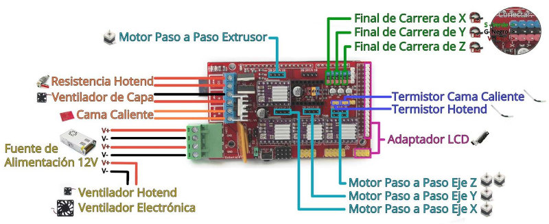
We will connect the 12 Vdc power supply, the 3 motors for the X, Y, Z axis.
2.1.3 Nema 17 stepper motors
We use three NEMA 17 motors. The Nema 17s have 200 steps per turn in principle. This means that with each step we obtain a movement of 1.8º per step.

Link datasheet Nema 17 (X17-1003LQCEF)
2.1.4 DRV8825 Drivers
The DRV8825 is a stepper motor driver board that has on a DRV8825_chip that allows control of stepper motors through arduino type programming software and firmware. The DRV8825 board can supply up to 2.5-A peak or 1.75-A RMS output current (with suitable 24V 25 ° C heat sink).

2.1.5 12 Vdc power supply
The power supply has the mission of converting the alternating voltage into a direct voltage. In our CNC, the power supply is in charge of transforming the current from the electrical network (220V50Hz) to direct current. It is a switching power supply. It has terminals for making the AC (L, N and GND) and DC connections (3 -V terminals and 3 + V terminals).

2.1.6 USB cable (A to B)
Cable with USB connectors Version 2.0 male (plug) type “A” to male (plug) type “B” of 5 pins, allows the connection between the Arduino Mega and the computer.

2.2 Connection of electronic components
First I attach the Ramp 1.5 on top of the Arduino mega 2560, be careful not to bend the pins of the Ramps, it must be attached carefully.

Couple the three DRV8825 drivers on Ramps 1.5.


Connect the power supply (+ 12v and -12V) to the Ramps and the USB cable from the Arduino mega to the computer.

Connect the Nema motor to the Ramps.

Connecting the motors to the RAMP1.4.

2.2.1 Pololu DRV8825 driver configuration pololu drivers.

Initially we connected the motors to the drivers and when moving the motors they got excessively hot just like the drivers, so we saw that we had to configure the current limit of the drivers.
DRV8825 Driver Current Limit.
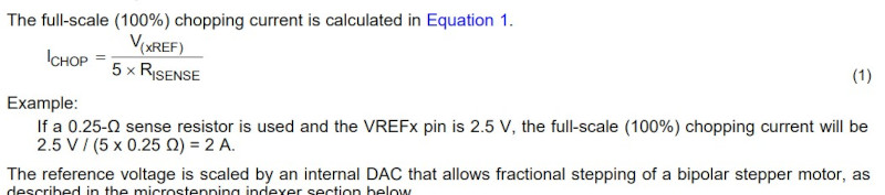


As we are going to use complete steps we will use 70%.

Vxref= 0.5 *0.71 = 0.355

Final connection of the three motors on Ramp 1.5.

2.2 FIRMWARE AND CNC PROGRAMMING
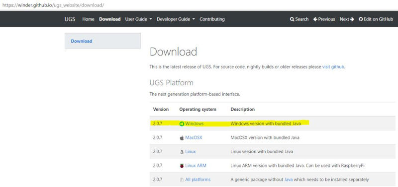
What is universal G Code Sender?. For those who want to start in the world of CNC, this is one of the best options, through the user interface developed in Java and completely intuitive "UGS" manages to put in your hands a complete CNC control system, all this at the same time. one-click reach. A full-featured gcode platform used to interface with advanced CNC controllers such as GRBL, TinyG, g2core, and Smoothieware. Universal Gcode Sender is a standalone Java application that includes all external dependencies and can be used on most computers running Windows, MacOSX, or Linux. To download the Universal G Code Sender software, click this Link UGSTo run it you need to have JAVA installe.
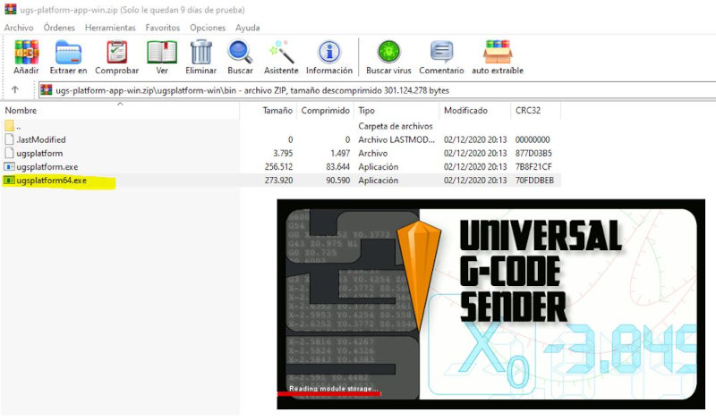
Open the file ugs-platform-app-win.zip and select "ugsplatform64.exe".

We decided to give the GRBL firmware a try because it is easy to configure and can be controlled using the Universal G Code Sender software. GRBL: The GRBL firmware is a key piece in charge of transforming the GCODE file into motor movement and is used in a great variety of CNC machines such as routers, laser engravers and a long etc.
I download the GRBL firmware for Arduino.
Follow the youtube manual “elprofegarcia”.

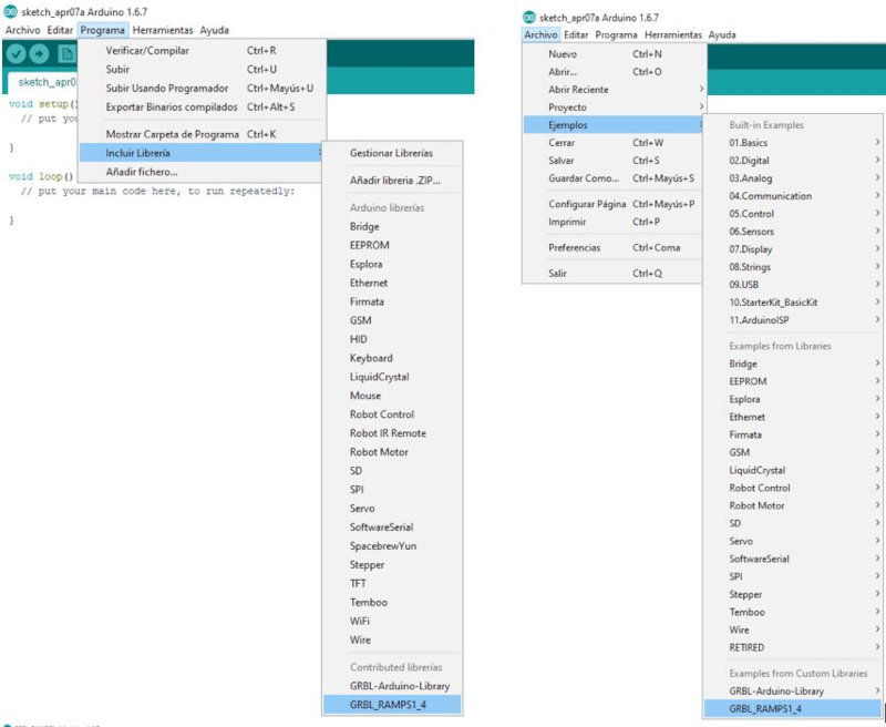
Add the GRBL library on Arduino.
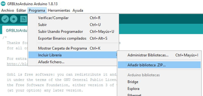

Open (Example / GRBL-Arduinio-Library / GRBLtoArduino).

Connect the Arduino Mega to the USB port of the computer and perform the following configuration in Arduino IDE.


I have compiled the program, but it does not move the motors, so we use another GRBL (File) for Ramps 1.4 that Álvaro Macian uses in the Fabacademy 2020 and that does work for us.

Open the UGS and connect the Arduino Mega / Ramps. Select the GRBL Firmware, refresh Port: COM3, select Baud: 115200 and connect.

Now from commands, we can put $$, as with Arduino ID, and the GRBL configuration comes out. (the most important parameters in our case are those of the motors, x, y, z step / mm, steps to move one mm and that depend on the motor and the threaded rod, default feed, default seek). See in the manufacturer the degrees that each step takes, 360 between the degrees per step, and it gives us the steps of a complete turn, for the rod, see the mm that it travels per turn. If, for example, the (propeller) rod makes one turn in a distance of 8mm, it will be necessary to divide the steps for one turn of the motor, between these 8mm for the turn. In this way I will obtain the mm of displacement for my motor and my rod, this is set for the x, y, z step / mm. (with the one mm rods, it stays as is).


- The parameter (step pulse, usec) with which we will indicate the pulse width that Arduino will recognize. (with 10 it works fine) ($ 3 = 10 (step pulse, usec).
- Default feed is the speed with load, and the default seek speed when searching for some position. The two should be the same, or with a slightly less load. This must be seen according to the user; the manufacturer does not provide information.
- If the motor vibrates or jumps, the speed is too high, the steps are wrong, or the pulse is wrong.
- At a very high speed, steps may be lost so the milling result will be poor.
- (step idle delay, msec) is the delay time, after placing an order. 15 usually works well.
- (acceleration, mm / sec ^ 2) acceleration of the motors, depends on the motors being used. It is advisable to start from a value of 30 and go up progressively, in case you want to put more acceleration. (500 high speed motors)
- The parameters (junction deviation, mm) (arc, mm / segment) (n arc correction, int) are used for plotting arcs and curves, with values of 0.050, 0.100 and 25 in this order, it works fine. Change if the curves do not work well, although they are valid for the layout of circuits.
- (n-decimals, int) put it to 3 decimal places, so you gain a little more precision than with 2.
- (report inches, bool) value 0 if we work in inches or set to 1 to work in mm.
- (auto start, bool) if it is set to 0, the Arduino must be programmed to start, while with a value of 1 it starts automatically.
- (invert step enable, bool) in case other drivers other than A4988 are used and it is necessary.
- (hard limits, bool) useful when using limit switches to stop the machine when it reaches the limits. Enable 1. Since this way when giving auto-home, it will look for the limit switches. With a value of 0, the home must be found automatically.
The movements are controlled in "Jog Controller", you have to configure the Step size XY, Z and the Feed rate..

2.3 Movement with a GCODE file
I have followed the following tutorial. We use Inkscape to generate the gcode file. Open Inkscape and import the image. Initially we will do a test with a circle.

Leave the default parameters and click on "Ok".

Vectorize Bitmap.

Select "OK" and another vectorized image will be generated. You must delete the non-vectorized image.

Select "Path / Object to path".

Select "Dynamic forwarding".

The following icon will be activated.

Select "Extensions / Gcodetools / Orientation Points".

Click on "Apply".

Select "Extensions / Gcodetools / Tool Library ...".

Select the "Cylinder" tool.

Change the parameters of the drill diameter “4mm”. Select the "Create and edit text objects" tool.


Select the circle again with "Edit course notods or control handles (N)".

Select "Extensions / Gcodetools / Path to GCode ...".

Select "Preferences" and name the file and directory. Go back to "Path to GCode" and click on "Apply".

Arrows will appear with the trajectory of the Gcode.

A ".ngc" file is generated.

Open the UGS. Select "File / Open ..." and select the file ".ngc".


Click on "Play" to start the gcode path.

3. My files
Firmware and Programming
Project Universal G-Code Sender "Circle" (.ngc)