13. Output Devices
For this week I chose to try out AccelStep stepper motor library and small OLED display.
Group work: power consumption measurements
As with previous weeks, we worked as a group with Ken and Mona. This week’s group work can be found at Ken’s site.
We used usb power meter to see that Arduino Uno and 2004 character display consumes about 108 mA with display backlight on, 56 mA with backlight off. Contents on display didn’t either have effect on current consumption or our power meter accuracy is too low. We also tried Agilent N6705B DC power analyzer.
Individual work
I’d like to power all electronics via usb, so I looked out for boost converters in Fab Inventory. I spent a while looking through FabLab Inventory list, but I didn’t like that I couldn’t copy text from there, so I tried cutting url and I found one that opens the same list on Google Docs and allows copying.
SAMD11C14 board design with a dead-end
I’ve been wanting to test out other microcontrollers than AVR. No particular reason, just to get comfortable with more than one line of microcontrollers. So I ended up design a board for SAMD11C14 microcontroller.
First thing was looking for existing designs and I found:
- SAMDino by Adrián Torres
- SAMD11C14 UART/UPDI programmer and SAMD11C14 devkit board by Quentin Bolsée
- Multi purpose SAMD11C board by Florent Lemaire
I got confused how to program SAMD microcontrollers, because different people use different methods. Maybe Adrián’s SAMDino was not the best place to get started with this, because his programming solution is the most complicated of these. Finally I got confident to believe that Atmel-ICE that FabLab has can program my SAMD board to have bootloader that allows it accept new programs via usb. So I should need a external programmer only once.
SAMD11 datasheet is not included in my repository, since it’s almost 14 MBytes. Only SAMD11 datasheet summary is stored in my repository.
While looking through SAMD11 datasheet chapters 7. Power Supply and Start-Up Considerations and 35. Electrical Characteristics I found the value for decoupling capacitor is 4.7 µF (Chapter 35.10 Analog Characteristics, 35.10.1 Voltage Regulator Characteristics) and if SAMD11 is interfaced with any signals higher than SAMD11 supply voltage + 0.6 V, a current limiting resistor must be used (Chapter 35.9 Injection Current).
For supply voltages from 3.0 to 3.6 V, injection current can be +- 1 mA.
For supply voltages equal or less than 3 V, injection current can be +-15 mA.
I’m limited to 3.3 V regulators that FabLab has, so I must use 1 mA injection current. For 5 V incoming signals value for current limiting resistor should be:
R = (Vpin - (VDD + 0.6 V)) / I_inj = (5 V - (3.3 V + 0.6 V)) / 1 mA = 1.1 V / 1 mA = 1.1 kOhm
1 kOhm resistor would (nominally) be too small, so I’ll select the next resistor value: 4.99 kOhm.
Linear regulator
Because I want to power this board via USB (USB supplies 5 Volts) and SAMD11 microcontroller operates on 1.62 - 3.63 Volts, I need to make lower voltage for SAMD11. I remember there are some linear regulators at FabLab, so I chose to use those. Linear regulator is a small electrical device that regulates it’s output voltage. It can drop voltage or smooth out “unclean” voltage that has variations on it. In this case it just drops voltage.
There were 3.3 V and 5 V regulators available, so I must choose 3.3 V to fit to SAMD11 operating range (also you can’t use 5 V regulator to regulate 5 V to 5 V, output voltage must be lower). Those 3.3 V regulators were available for 100, 150 and 1000 mA current. I chose 1000 mA just not to worry about current consumption in most cases.
Exact model of this regulator is ZLDO1117G33DICT-ND so I googled it and opened Digikey’s product page and datasheet. From datasheet I see that I could make this regulator work as 3.0 volt regulator or lower than that by using resistors for voltage division. Now I just want to get this done and keep going with fixed 3.3 voltage. On Typical Application Circuits input has 10 µF capacitor and output has 100 µF capacitor. I will use those.
Programming header and FTDI header
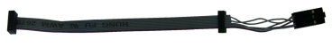
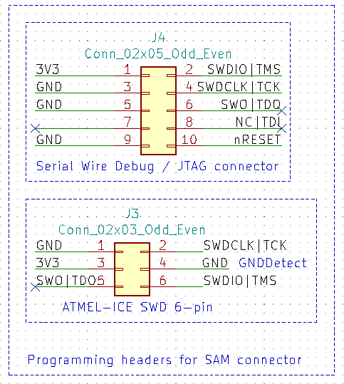
I could go with either 6-pin SWD header or 10-pin JTAG or SWD header. I decided to use both, because 10-pin 1.27 mm pitch header might be more common in programmers, but I don’t remember seeing those in FabLab. I’d like to use 6-pin 2.54 mm pitch header, if it works. I traced wires of Atmel-ICE programming cable from 10-pin to 6-pin connector to find out that it is 6-pin SWD connector when connected to SAM port of ICE programmer.
I was wondering should I put “FTDI” header to board to communicate via UART, or would I be able to use UART to PC via USB. So I decided to set up Arduino for SAMD11C14 microcontroller so I can test will it compile, right? Here’s where things start to go downhill…
I followed Adrián’s documentation on setting up Arduino IDE for SAMD11 boards. So first thing is to download bootloader (even if it is not needed for this compile test, I downloaded it to easily track steps I’ve done). Bootloader allows board to be programmed via Arduino IDE using USB instead of external programmer. I downloaded existing bootloader from MattairTech GitHub, sam_ba_Generic_D11C14A_SAMD11C14A.bin to be exact. I also saved to my GitLab.
There’s also existing board library for Arduino IDE that utilizes bootloader. (Backup at this week’s files folder)
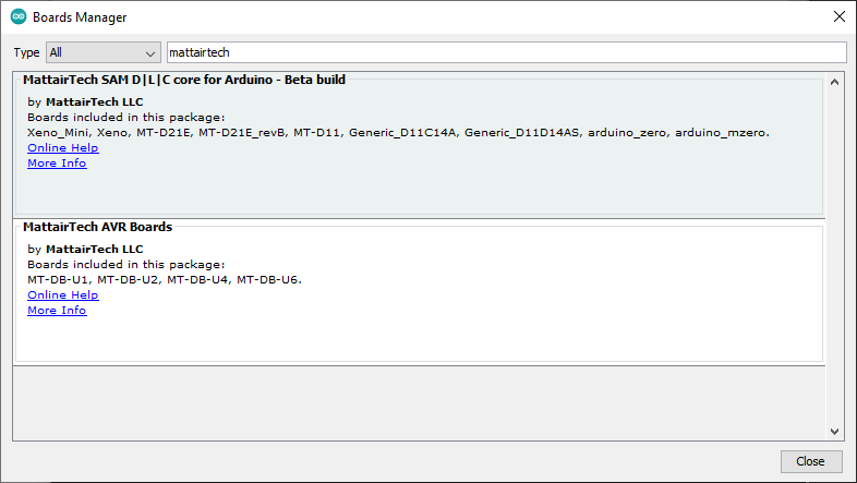
In Arduino Boards Manager I searched with term “mattairtech” to find SAM D|L|C core. I also backupped it from C:\Users\Antti\AppData\Local\Arduino15\packages into a zip file.
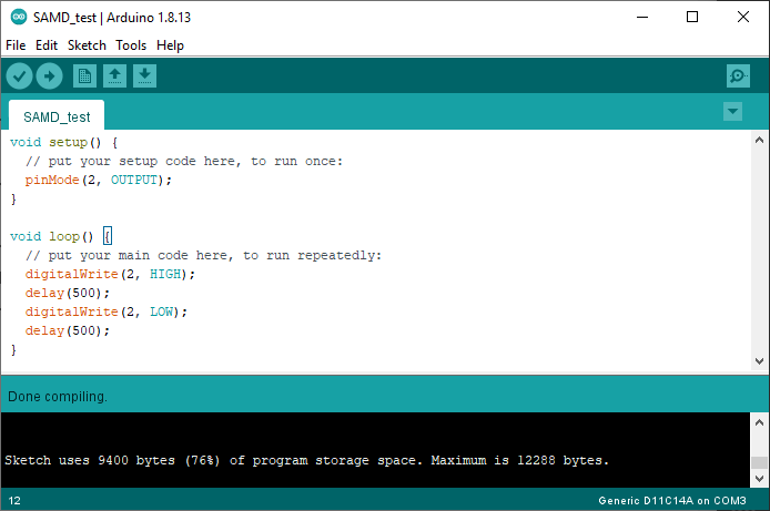
First warning for me was that while small “blink” program compiled, it takes a TON of memory for such a simple program, more than 9 kB of available 12 kB! (4 kB reserved for bootloader of total 16 kB flash that SAMD11C14 has)
For ATtiny412 that same code takes 0.67 kB of 4 kB.
So I quickly proceeded to download AccelStepper library.
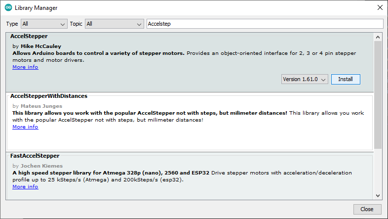
After installation I opened ConstantSpeed example, which is rather simple. I hate to be right on this thing.
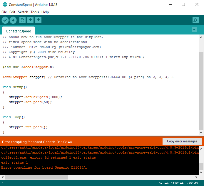
c:/users/antti/appdata/local/arduino15/packages/arduino/tools/arm-none-eabi-gcc/4.8.3-2014q1/bin/../lib/gcc/arm-none-eabi/4.8.3/../../../../arm-none-eabi/bin/ld.exe: C:\Users\Antti\AppData\Local\Temp\arduino_build_245165/ConstantSpeed.pde.elf section
.text' will not fit in regionFLASH’c:/users/antti/appdata/local/arduino15/packages/arduino/tools/arm-none-eabi-gcc/4.8.3-2014q1/bin/../lib/gcc/arm-none-eabi/4.8.3/../../../../arm-none-eabi/bin/ld.exe: region `FLASH’ overflowed by 2496 bytes
collect2.exe: error: ld returned 1 exit status
exit status 1
Error compiling for board Generic D11C14A.
SAMD11C14’s 16 kB flash memory is almost 2.5 kB too small for this simple example! While ATtiny1614’s 16 kB memory would be just fine since this program would take only 5.1 kB of it.
I tried different board library I found via Hackaday, but it was based on the MattairTech one, so also different library would need 9 kB flash just for blink. Unacceptable!
I’m forced to change either microcontroller or output device I use.
New board!
How to fix too small memory? Go bigger! Next step up from SAMD11 is SAMD21, and FabLab has SAMD21E17A-U variant.
Useful links to start with:
- SAMD21E Development board at Hackaday
- SAMD21E17/E18 devkit board by Quentin Bolsée
- Final Project by Florent Lemaire
Datasheet for SAMD21E17 was easily found at Microchip website. I saved it to my GitLab, too.
Schematic design
In datasheet I quickly found Schematic Checklist.
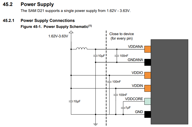
SAMD21 needs some more capacitors than SAMD11 or ATtiny 1-series.
I reused SWD-headers that I created for SAMD11. Both 10-pin 1.27 mm pitch and 6-pin 2.54 mm pitch were used. I also reused powering schematic and regulator. There were quite a lot of unused pins, so I connected those to headers and also made some 5V, 3.3V and GND headers available. For powering steppers with 12 volts, I placed 2-pin headers for 12 V and GND near stepper driver.
I will ignore the “interfacing with 5 volt parts” thing now. Maybe I’ll make a small logic-level converter board for that purpose if I need one.
During first minutes of layout design I added 10kOhm pullup resistor for SCL1 and SDA1 lines.
Open schematic in new tab to see it in full size.
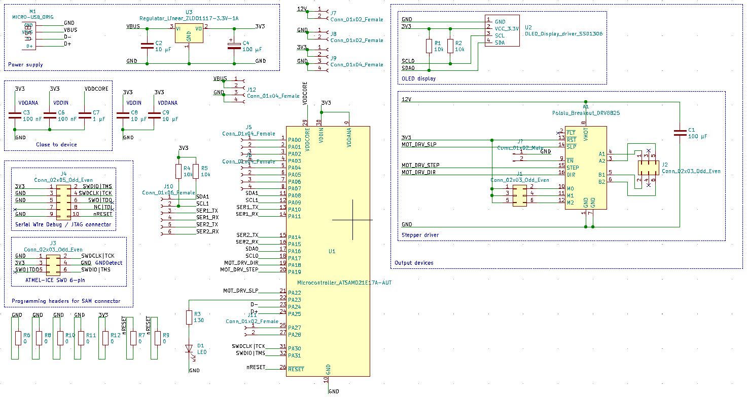
Later in layout phase I needed to add 7 pieces of 0 Ohm resistors. One of those connections has two 0 Ohm resistors next to each other to make sturdier connection between two large ground areas.
After having seen how Ken solved stepper stuttering, I added another jumper option to pull enable pin of stepper driver strongly down instead of weaker pull-down resistor on stepper module.
On machine design I left enable pin unconnected, because Pololu product page states very clearly “The default state of the ENBL pin is to enable the driver, so this pin can be left disconnected.”
Layout design
This was surprisingly lot of work! But I got it done!
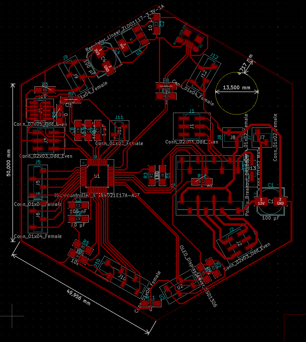
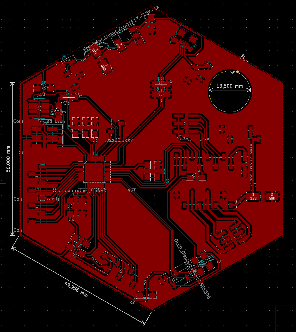
The circle cutout is for motor power wires to have some physical pull resistance. Rather move the whole board than rip power headers off the board.
Manufacturing and soldering
I manufactured my new board with LPKF ProtoMat S62, a process I will add to Electronics manufacturing page even though none of us Fab Academy students used it that week, but topic-wise that’s the best place for documentation.
I collected components I need for board and it took one evening (3-4 hours) to solder those. One 0 Ohm resistor pad broke off (3.3 volt jump under stepper driver) so that took some trials and errors to fix it. Just a solder ‘blob’ was quite difficult to get just right. I then tried small piece of solder wick, but it crumbled to almost dust, so I ‘fed’ solder to solder wick and then cut the piece I need. That worked quite well, also relatively easy to solder.
6- and 8-pin headers needed to be constructed from 2 pieces of 3- or 4-pin headers that needed some sanding to be able to fit close enough to each other.
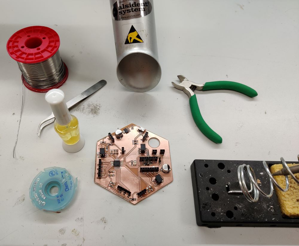
Finished board and most the equipment I used to solder it: soldering iron, solder, solder wick, tweezers, soldering flux, wire cutters and solder fume extractor.
Lesson learnt #1: Break functionality into smaller pieces and stop cramming everything into one board.
I soldered two wires to provide 12 V stepper motor power to board. I also used those to test board for short circuits and I found some weird behaviour: when connected to 5 V header there can be short circuit between 5 V and ground, if wire connected to 5 V header leans towards usb port. Leaning towards hole won’t make a short circuit. After desoldering 4-pin header between usb port and hole I realized it: my power wire uses too long pins that go through header and make contact with pcb! I cut those pins to be a bit shorter and the boards seems to be fine now.
Lesson learnt #2: headers have open ends, don’t connect too long male connectors to those!
Later I remembered that our programmer from Electronics production week have some resistors and capacitors on usb data lines, did I make a mistake by not including those? Having a look at programmer schematic reveals that there are 50 Ohm resistors just before ftdi chip and 10 pF decoupling capacitors (capacitors connected between signal and ground) between usb-connector and 50 Ohm resistors. Lucky for me, it seems that Adrián, Quentin and Florent have produced working boards without those, so I guess I can continue.
Lesson learnt #3: Before next usb-connected design, check what is the function of those 50 Ohm resistors and 10 pF capacitors. Should I include or ignore them? My guess is that 50 Ohm resistors are for impedance matching and 10 pF capacitors are for decoupling, which means boards likely work without those, but if there’s any wacky behaviour, adding those just might solve it.
Edit: FT230X datasheet uses 27 Ohm resistors and 47 pF capacitors in USB Bus Powered Configuration (chapt. 6.1). We used the closest value components available. Datasheet backup also in my repository.
Programming SAMD21E
Oh boy, this the part where everything comes together, does my first SAMD design work or not.
First, I setup my pc to be ready to program SAMD21E by downloading bootloader file I want to send to SAMD21E and downloading edbg, which is a utility to program Atmel microcontrollers through CMSIS-DAP protocol.
Like before, I downloaded existing bootloader from MattairTech GitHub, sam_ba_Generic_x21E_SAMD21E17A.bin to be exact. I also saved to my GitLab.
Downloading edbg proved to have one unexpected extra step. Because developer of edbg has changed GitHub Actions CI recently, new builds are available only as artifacts that require you to be logged in to access those. I downloaded latest build that developer himself had committed to. Saved also on my gitlab repository as an .exe file and as a zipped folder.
I found no headers to 10-pin 50 mil ARM-JTAG connector, so I must use 6-pin 100 mil SWD connector.
After navigating to folder that has edbg.exe and desired binary to be written, I can program my board with command:
edbg -bpv -e -t samd21 -f sam_ba_Generic_x21E_SAMD21E17A.bin
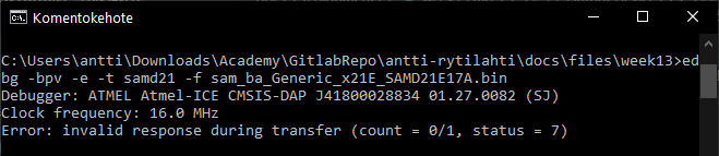
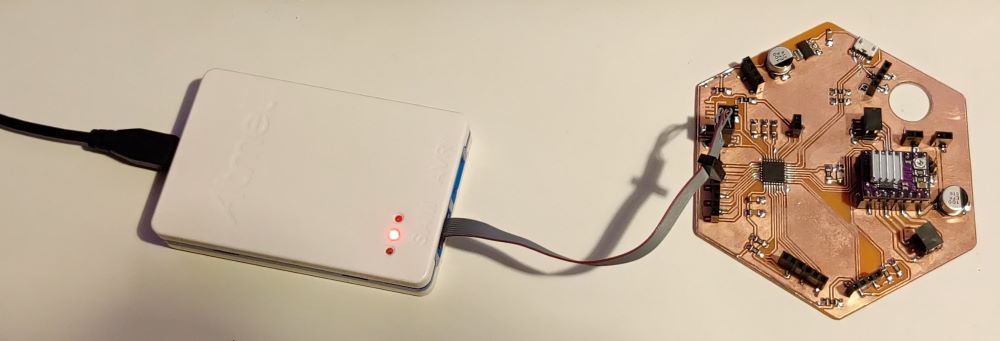
This was a letdown. Just to be sure, I try again with same result. To rule things out one by one, I make sure my decision to have power delivery via SWD header isn’t a mistake, so I connect external power bank to micro-usb.
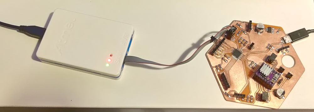
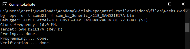
Immediately hope starts to shine as programmer lights up one green led signifying Target power OK according to ATMEL-ICE User guide. edbg programming utility doesn’t hesitate either, in a second or two it executes my programming command and my SAMD21E board is ready for use! (I hope)
Next step is to find out does it get recognized by Arduino IDE, or should I follow Florent’s steps as he seems to be the only one who documented his board to work with Arduino IDE, though he used a different bootloader.
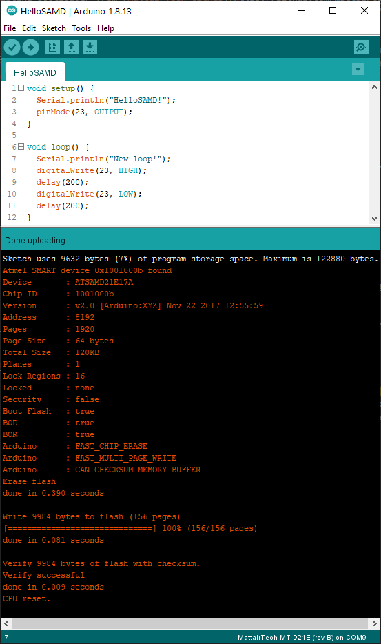
It did get recognized in Arduino IDE and I was able to write small test that writes back on Serial and it worked! However when I tried to get led working, my board stopped being recognized by pc, no idea why.
Little debugging showed that my pc usb port is still working and my cable isn’t broken so the problem has to be my board… However Atmel-ICE still lights up green Target power OK light when my board is powered by powerbank via micro-usb connector and ATMEL-ICE is connected to SWD header. So I rewrite bootloader and it completes without any signs of broken board. Also my board got recognized again by pc and Arduino IDE, so I wrote new test code to my board that sends text via Serial and blinks led, which went well.
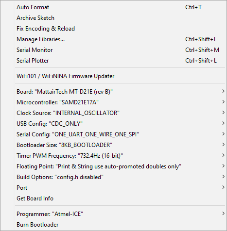
My test code with write operation and settings on Arduino IDE Tools menu.
Notes for upcoming documentation:
For OLED display, check https://github.com/olikraus/u8g2 and https://github.com/adafruit/Adafruit_SSD1306
I2C has reserved addresses: 0000 000 - 0000 111 and 1111 000 - 1111 111, I chose 1010 101 for main board and 1010 110 for secondary board.