11. Input Devices
This week covers various input devices. On group work we take a close look to DHT11 humidity and temperature sensor. For my personal tasks I chose to explore VL53-series distance sensor. Capacitive touch sensor also spikes my interest, but I haven’t had time for that yet. I might explore and document more about capacitive sensing during final project.
Group work
Our group consisted of me, Mona and Kenichi.
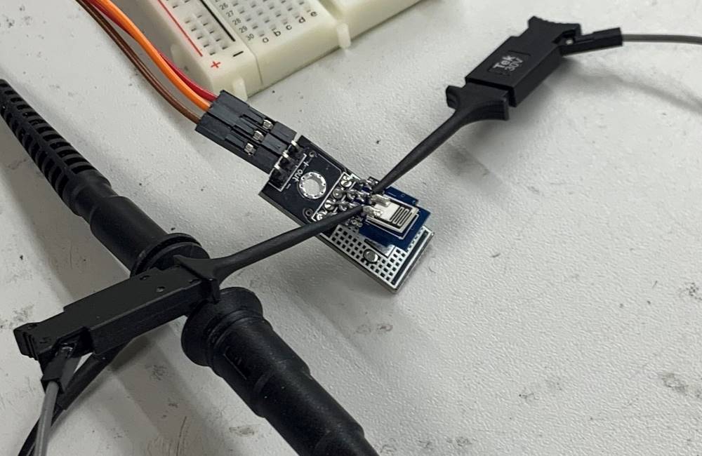
For group work we got disassembled DHT11 humidity and temperature sensor and with oscilloscope we looked into digital communication between sensor module and Arduino Uno. After that we got onto the real reason why sensor module cover was removed. Our instructor, Juha-Pekka told us to probe directly into humidity sensor and probe the analog signaling between capacitive humidity sensor and DHT11’s embedded microcontroller that takes care of step response type measurements and packages them into digital data to be sent out.
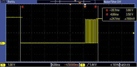
Minor rant: Sorry for the oscilloscope image quality. Our basic scopes (Tektronix TBS1202B-EDU) have satisfactory 800x480 px screens, but almost unusably small 2.5 kpoints memory depth. These images were saved on the only mixed-signal scope (Tektronix MSO2002B), because it has 1 Mpoints memory depth, combined with ridiculous 480x234 px screen.
Code for DHT11
We tested DHT11 with DHT sensor library by Adafruit. Library version we used also archived on Gitlab repository. I still think our instructor had a different library, since his code could fit to ATtiny412 (our did not) and his code needed many minor reworks to work with Adafruit’s library. Here’s the example instructor showed us, adapted to Adafruit’s DHT library.
#include <DHT.h>

#define DHT_PIN 4

DHT dht(DHT_PIN, DHT11);

void setup() {
  Serial.begin(9600);

  dht.begin();
  delay(2000);
}

void loop() {
  Serial.print("Temperature: ");
  Serial.println(dht.readTemperature());
  Serial.print("Humidity: ");
  Serial.println(dht.readHumidity());
  delay(5000);
}
Also available as .ino file.
Digital communication between sensor module and MCU
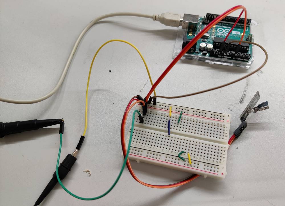
We connected DHT11 to Arduino Uno and oscilloscope probe to sensor data and ground.
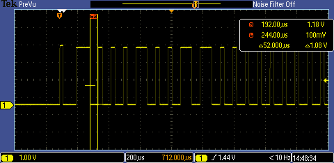
DHT11 uses Single-wire protocol (not to be confused with 1-wire protocol!)
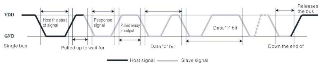
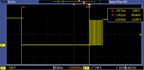
Whole communication lasts for 24 milliseconds, leading with 20 ms low pulse by Adafruit’s DHT library for Arduino, followed by 4 ms of active communication.
Communication is initiated by pulling data line low for more than 18 ms.
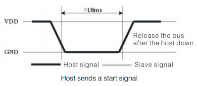
In our case this matches with our 20 ms low pulse.
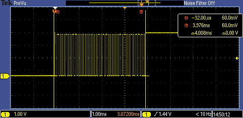
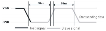
Before data transmission, there’s a quick handshake.
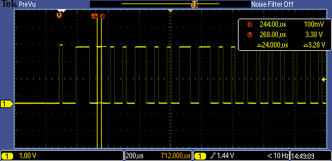
Data transmission consists of 0 and 1 bits, represented by pairs of low and high pulses.
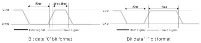
Both bits share a 50 µs low pulse that is followed by a 26-28 or 70 µs high pulse. Duration of the high pulse determines the transmitted bit as 0 or 1. Short 26-28 µs high pulse for 0, long 70 µs for 1.
Analog measurements from humidity sensor
We connected small clamps to second oscilloscope probe in order to be able to connect directly to humidity sensor.
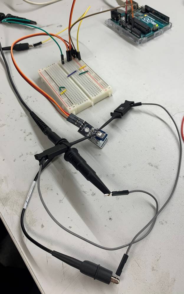
We started observing the sensor first in a long timescale (2 seconds/div) to see how often it is actively measured.
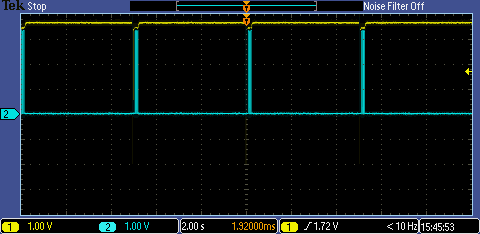
In the next picture we see that humidity measurement (blue signal from probe #2) takes a lot longer than communication between sensor module and microcontroller (yellow signal, probe #1) that takes about 24 ms.
Time gap between communication and new humidity measurement is about 59 ms, during which the sensor module mcu is actively working on something, based on variations in high signal level.
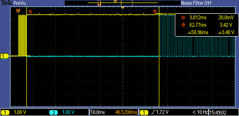
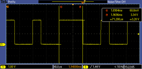
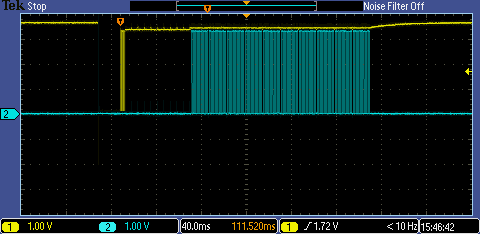
Next we have two measurements, one with “dry” sensor measuring room air, another with more humid sensor, due to being breathed at.
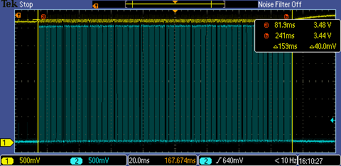
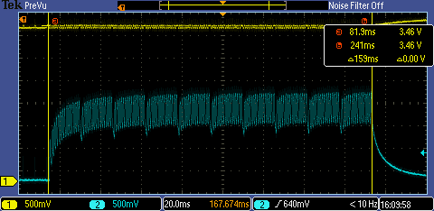
We see that sensor takes 10 series of 15 samples. The more humid the environment is, the higher the capacitance and slower the slew rate (rate of voltage change per time unit).
Almost square pulses for dry air.

Heavily skewed pulses when sensor is humid.

Unlike digital Single-wire protocol, these analog pulses are too difficult to decode without having more design-level knowledge of the sensor.
Individual work
VL53L1X distance sensor
Besides having interest on capacitive sensing, VL53-series distance sensors immediately stood out for me. I vaguely remember running into those when sketching about on could I add memory slots for my sit/stand desk at home. Our lab had VL53L0 sensors and VL53L1X sensor modules. I chose to use these ready-made modules and to design a pcb for it. Product page of the sensor itself, Datasheet Rev.3, Nov 2018
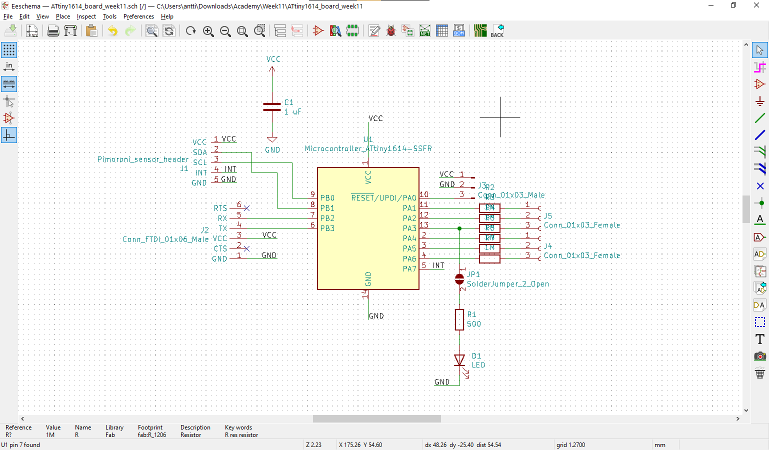
What I need for a pcb?
- MCU, ATtiny1614, 16 kB memory (+12 io)
- 1 uF cap for mcu
- UPDI header (-1 io)
- FTDI header (-2 io)
- Pimoroni sensor header (-3 io)
- no pullup resistor for I2C bus, sensor module has 10kOhm pullups, possibly leave open pads for future use?
- headers for rest of io (6 io pins left)
- led + resistor connectable by solder blob
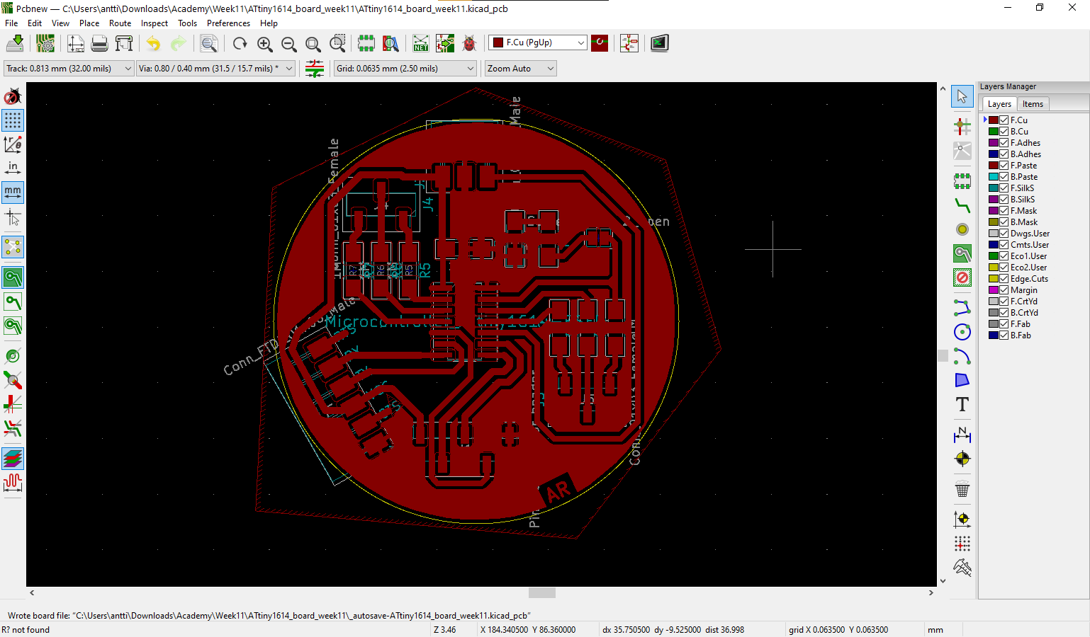
PCB design process in KiCad documented in Electronics design week, so I won’t go into low-level design here (how to add a component to schematic, how to wire components etc.)
I was about put pull-up resistors for I2C bus lines, but by a chance I noticed components with 103 label on sensor module. I realized those could be 10 kOhm resistor banks, so I followed traces from SDA and SCL pins to see if those end up in those 103 components. Since both signals went to those 103’s, I checked the resistance between VCC pin and SDA/SCL pins when module was not connected to any board. I got readings of 9900-10000 Ohms, so I decided to trust that those resistors provide pullup that is strong enough and not to use pullup resistors on my pcb.
On pcb design, just as a precaution to later try capacitive sensing, I decided to to put resistors in between unused headers and mcu as it seems to be beneficial to have large resistors in series with io pins. If I want to to something else with those io’s, I can solder 0 Ohm resistors to those pads.
I also added a led with resistor to one pin, but also a solder jumper so I can disconnect led and resistor if I want to do something else with that pin.
My pcb files as a zipped folder.
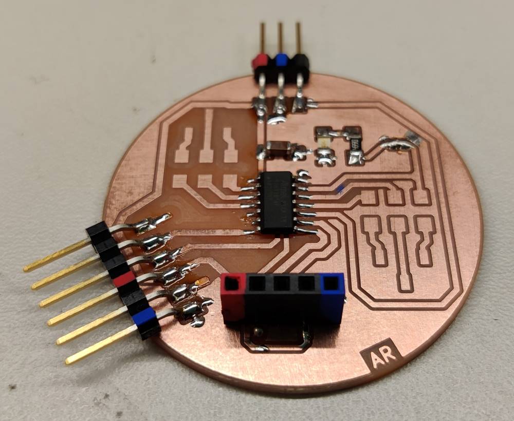
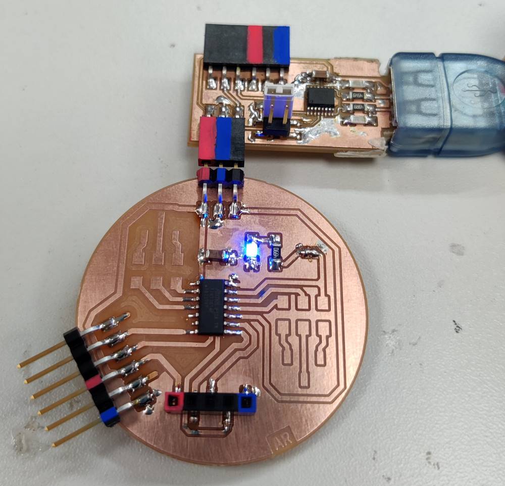
I only populated components I need. Unpopulated pads are related to capacitive sensing and can easily be added later if needed.
First test with new board was blink, of course :D (ATtiny programming via UPDI using Arduino IDE will be documented on Electronics design week)
#define LED 10 // Physical pin 13

void setup() {
  pinMode(LED, OUTPUT);
  digitalWrite(LED, HIGH);
}

void loop() {
  digitalWrite(LED, LOW);
  delay(400);
  digitalWrite(LED, HIGH);
  delay(400);
}
I installed Pololu VL53L1X library in Arduino library manager. I started exploring with “Continuous” example code of that library with high hopes, as it also happens to match with Adrianino’s VL53L1X code and I’m using the same microcontroller.
Code takes 7688 bytes of program memory. Good thing I didn’t go for microcontroller with smaller memory! (like ATtiny412 with 4kB memory. The actual reason why I selected microcontroller with bit bigger memory was this week’s group work: example code took 5+ kB and couldn’t fit onto ATtiny412)
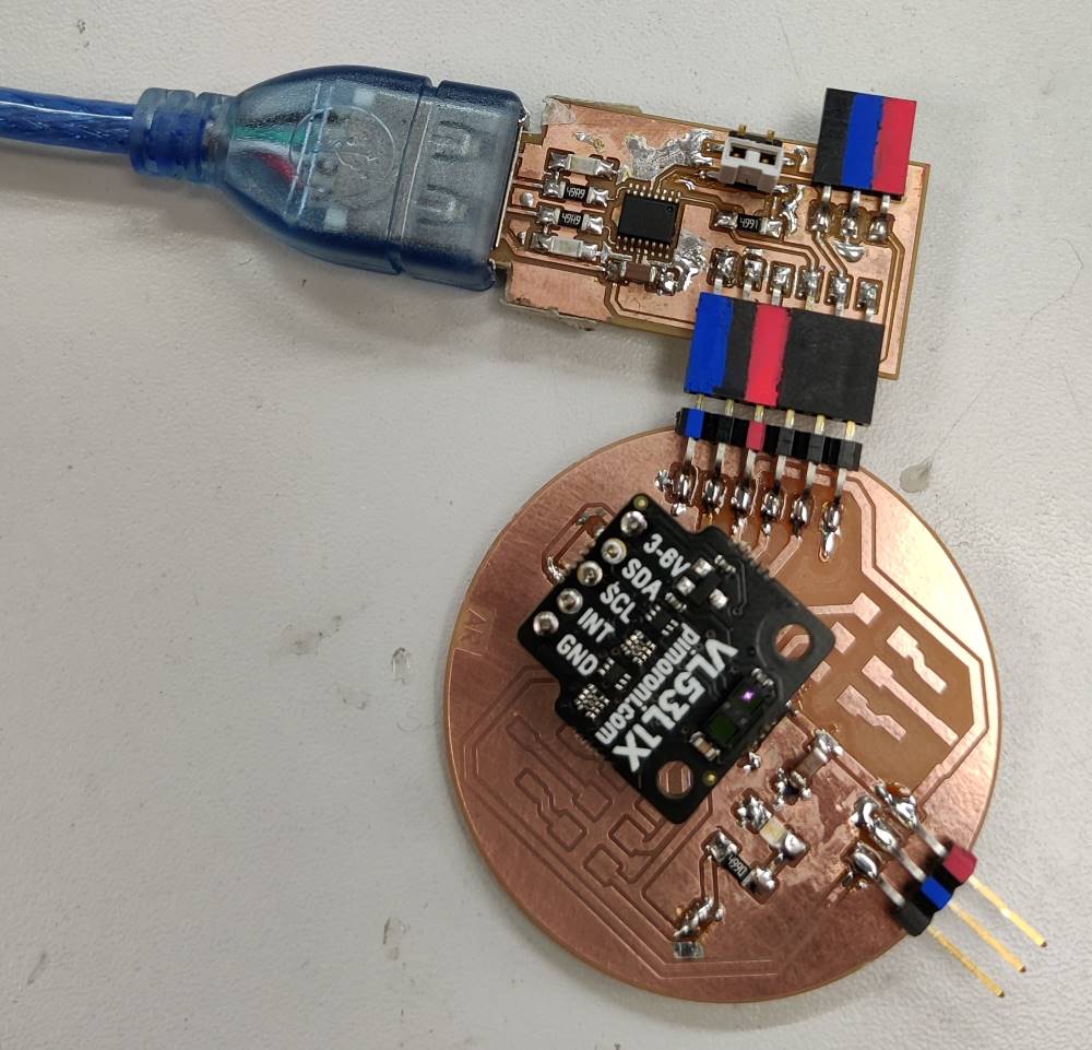
My input pcb with distance sensor, connected to FTDI header to have UART communication.
If you look closely, you can see a dim purple dot on the sensor module, in the actual sensor. It is the transmitting side of the sensor sending 940 nm infrared laser pulses. You can’t see it with bare eyes, but digital cameras see it blinking when measurements are ongoing.
Code I used for ATtiny1614 to interface with VL53L1X.
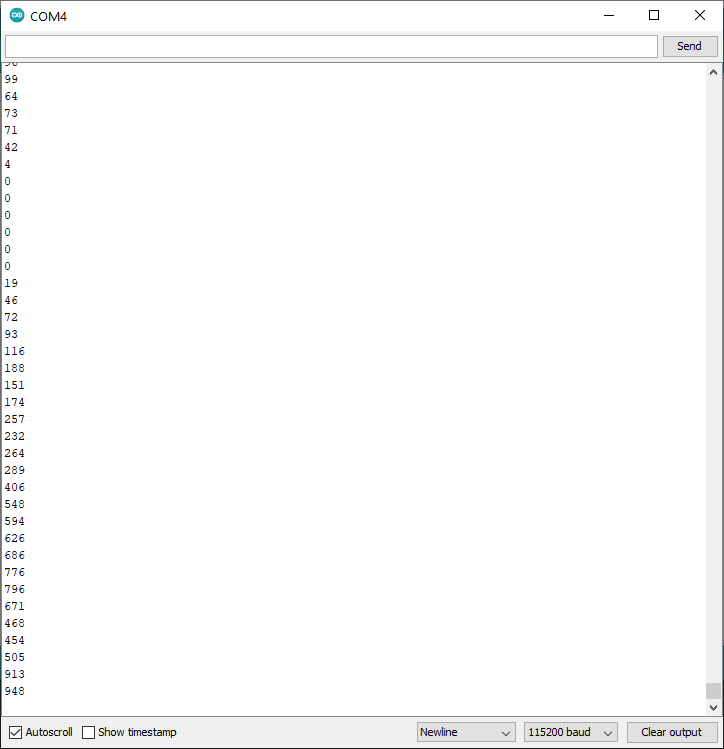
Distance readings (in millimeters) that seem to be ok.
Capacitive sensor
The most interesting application is to have touch sensing to work through another material, like Matthew Keeter’s Fab Boombox which has similar implementation to what I’d like to do. Also Neil’s links to Matt Blackshaw’s input week and Matthew Keeter’s input week have good information.
I will explore this later if I have time. Input week pcb should have capability to be used in exploring capacitive sensing.