14. Networking and Communications
This week I make boards communicate with each other in manner that is not limited to fixed number of boards.
Group work: Send a message between two boards
Like previous weeks, I did group work with Mona and Ken.
Difference between bus and network
So far we have used fixed connections that won’t work if you add or remove devices. On networking and communications lecture we were introduced to two new concepts: bus and network. Both are capable of having communications with varying number of devices, but the difference is need for routing. In a bus there’s a straight connection between devices and any device can communicate with any other device without routing via in-between devices. In a network the target device may not be in a straight connection with sender, so the communication needs to be routed via other devices, often via multiple different routes.
Communication via serial bus
This week’s instructor, Juha-Pekka emailed us a simple code that uses Arduino’s SoftwareSerial library to communicate between boards. Similar code was used in FabAcademy 2018 in Oulu. Code responds to any character received via serial bus by blinking a led. If received character matches with node variable, led is blinked again and board sends a response “node ” + node variable to serial bus.
2-board demo on breadboard
To test the code we connected two echohello boards from electronics design week to breadboard with ftdi headers connected pin-wise (tx to tx, rx to rx, vcc to vcc and gnd to gnd) and added jumper wires that were connected to laptop via usb cable with in-built ftdi chip and ftdi pins.
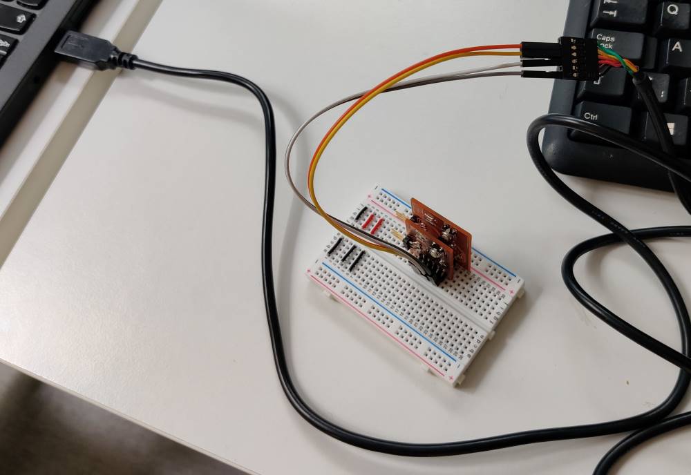
In Arduino IDE we sent characters to serial bus and boards responded with blinks and responses.
Add screenshot from serial monitor with responses
3-board solution with cable
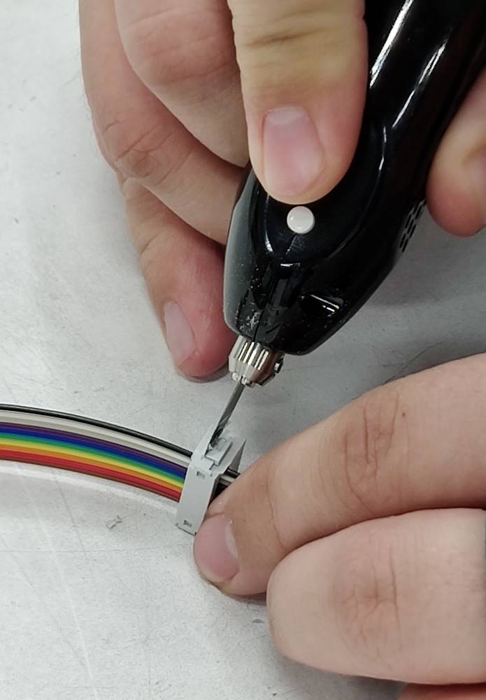
To add more boards we had to replace breadboard with custom cable and make the cable. We advised to select IDC connectors for easy assembly, but the widest of those was 2x5 pins and ftdi header on echohello boards has 1x6 pins. However only 4 pins are used, so we can work with 2x5 connectors. Four connectors were used with 8 cm distance of each other. A bench vise was used to close connectors.
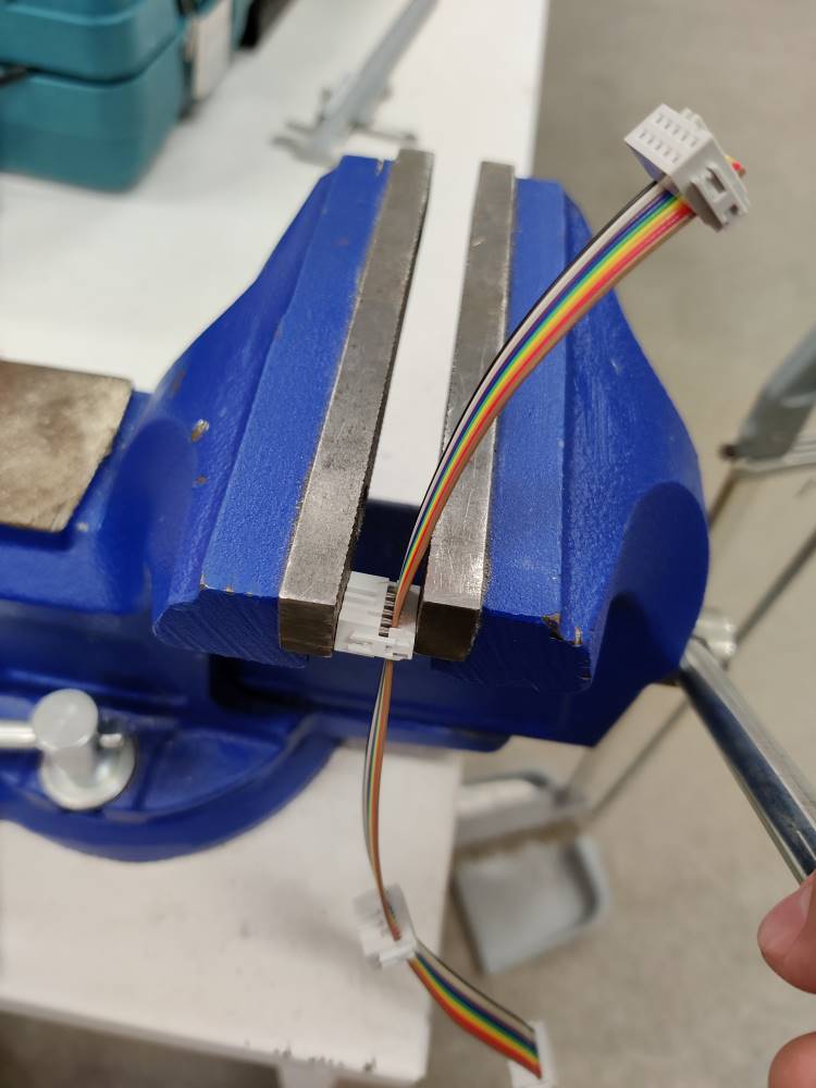
Problems arose when we realized our connector won’t fit together with the 6th pin. Pin conveniently sits outside of connector, but connector assembly collides with pin.
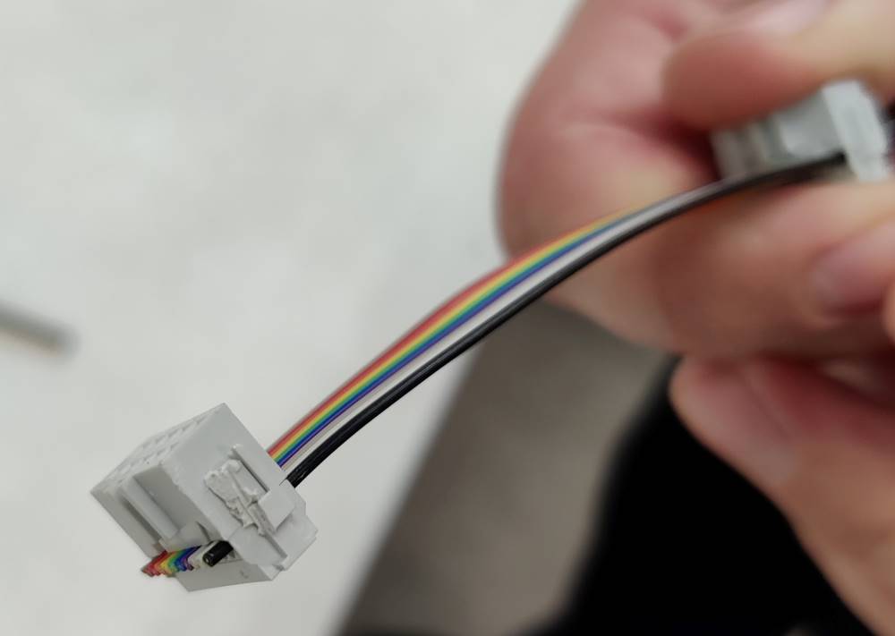
Luckily Gleb had demonstrated ultrasonic cutter two weeks earlier, so connectors were reworked with ultrasonic cutter.
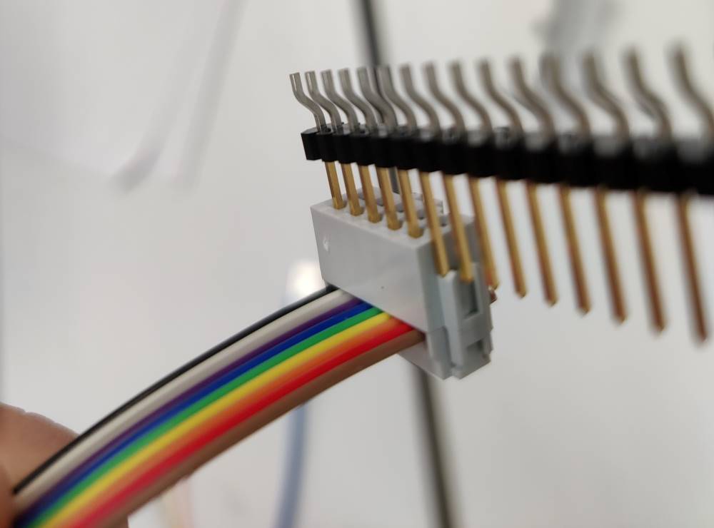
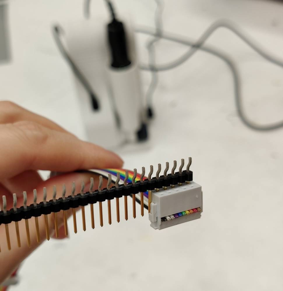
Reworked connector still holds up and doesn’t try to split into two.
Now all pins fit nicely. Ultrasonic cutter in background.
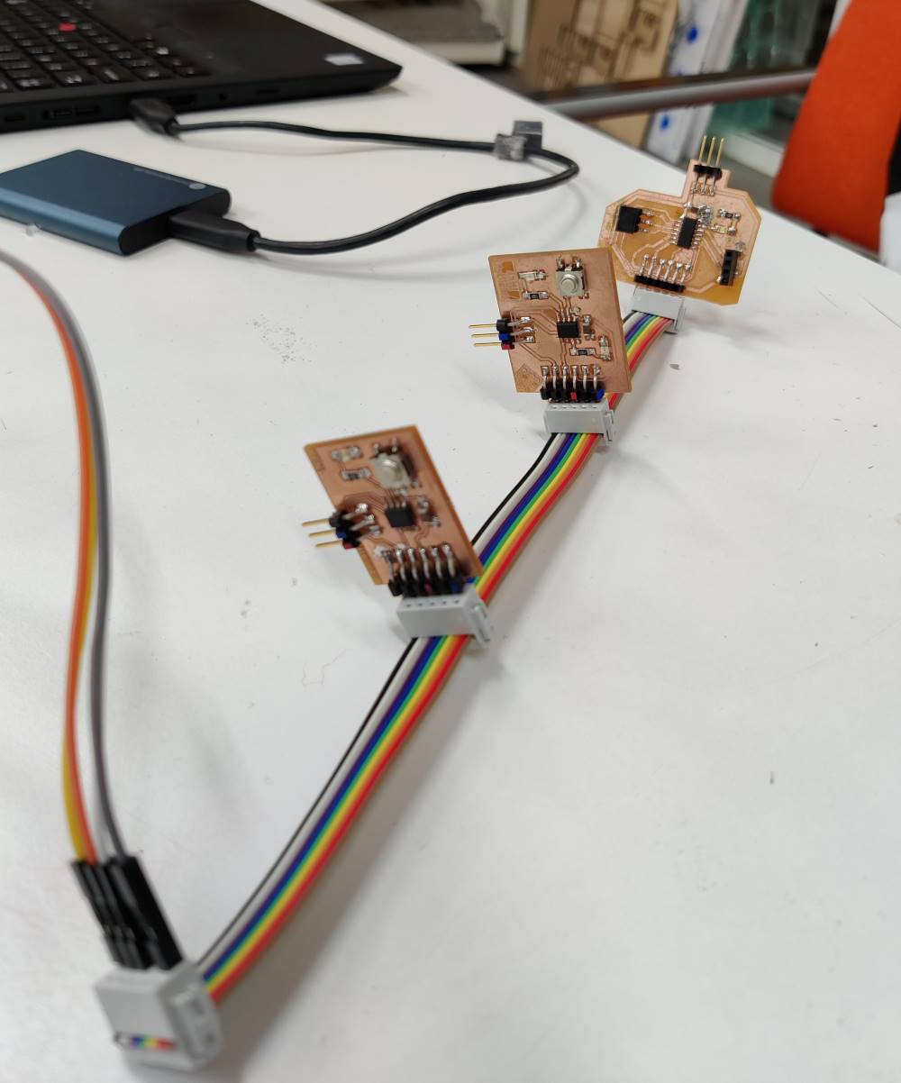
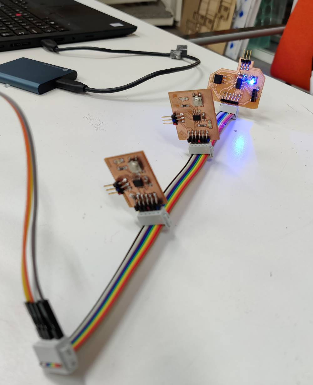
Test with 3 boards
All of us used one board of our own, me and Ken used echohello boards, while Mona was unlucky with her board as UPDI connector and it’s pads got damaged so she used her input week board.
Ken board used this code with char node variable set to ‘1’, while my board used the same code with char node set to ‘2’. Mona’s board has char node set to ‘3’, and also uses different pins due to having larger microcontroller. Code for Mona’s ATtiny1614.
Besides our three boards, usb-to-ftdi converter was used to send commands from pc to our bus and boards, like on 2-board demo on breadboard.
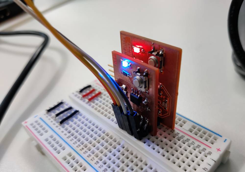
All boards blink when they receive a character.
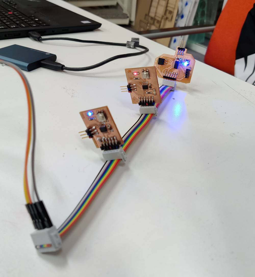
When sending response to matching node character, the responding board only is blinking.
Individual work
For this week I plan to connect my input week board with output week board via I2C, maybe also add OLED display from output week to it, too.
Currently I’m facing issues with my output week board, so there’s yet nothing to show this week, yet.
I2C bus between input week and output week boards
I want to connect my input week’s ATtiny1614 board with my output week’s SAMD21E board via I2C and prove connection as working by forwarding incoming messages to pc via USART. If I power my input week board via programmer, that’ll make it work on 5 volts and use I2C pins on 5 volts, which might not be good for 3.62 volt tolerant SAMD21E. So I must power SAMD21E board via usb and on-board regulator and power my input week board from output week board 3.3 volt headers.
Notes for upcoming documentation:
I2C has reserved addresses: 0000 000 - 0000 111 and 1111 000 - 1111 111, I chose 1010 101 for main board and 1010 110 for secondary board.