11. Input devices
This week I worked on producing a PCB that featured a sensor and writing code to operate such board and interpretate the data collected by my sensor.
Breadboarding
The first step in this week assignment was to prototype a sensor board by using an Arduino and a breadboard to start understanding sensors and the code behind it.
Piezo
On the breadboard I worked with a Piezo. This board was meant to sense contact between a phyisical body and the Piezo. The main issue with this board was to calibrate the threshold so to get a reading each time the board came into contact with a body and to send a line to the serial monitor only once per contact.
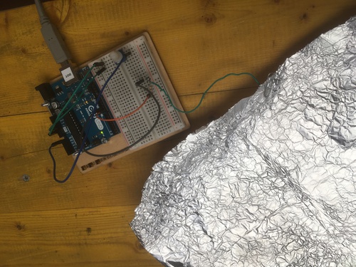
Capacitive Sensor (Breadboard)
The second breadboard test was a capacitive sensor (which I later iterated as milled PCB). This board worked in such way:
- it first ran 4 cycles of reading at what speed the sensor would charge\discharge
- this cycles went to define a threshold
- in the following loop it would confront any further reading with the threshold
- for each reading below such threshold it would communicate to serial monitor that the sensor was not being touched
- for each reading above such threshold it would communicate to serial monitor that the sensor was being touched
- in the following iterations of the code, it would also communicate threshold, and charge\discharge values
PCB
Once I sort of understood the functioning of the capacitive sensor, and I sort of understood the logic of the code provided me by tutor, I went on to design and produce PCBs that I could use this code with.
The workflow was the usual:
- design on EAGLE
- cam via FabModules
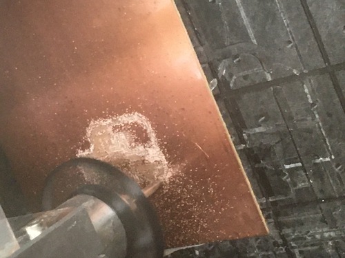
- production on the Roland
- soldering
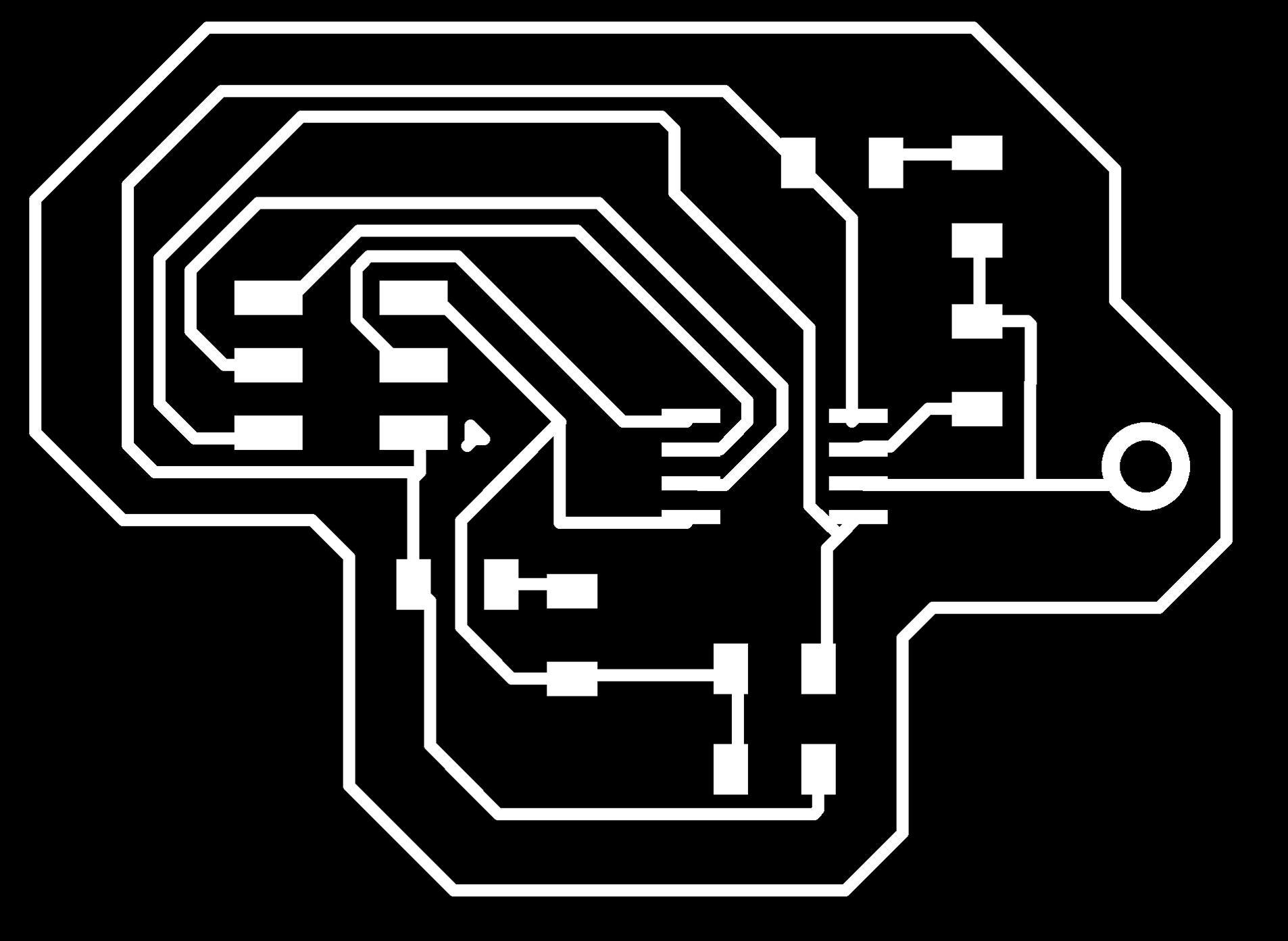
CapSens_44
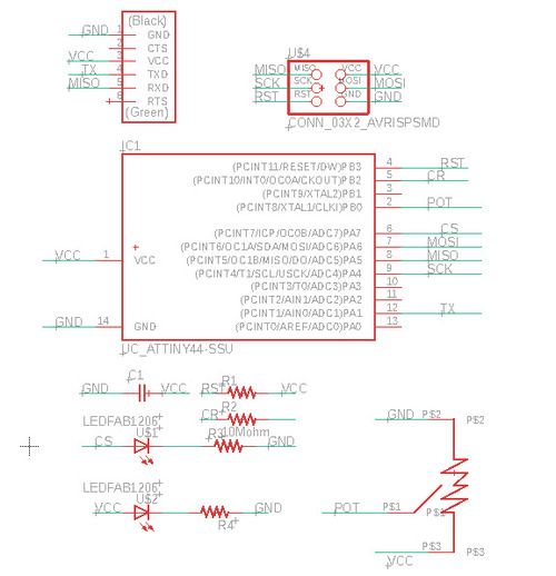
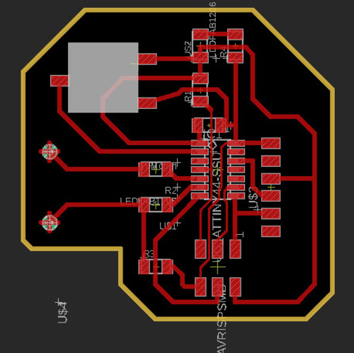
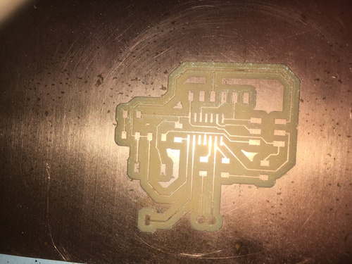
The first board I milled was based around an ATtiny44, it also featured a potentiometre.
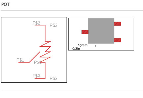
Since the compontent was actually through hole, I designed a new library with space to bend the pins of the potentiometre and solder it.
The potentiometre was needed to “trim” the threshold in my code in order to obtain more precise readings from this board.
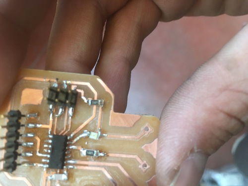
The first iteration of this board presented two separate holes for jumpers to be connected as my sensor, I fixed that in the next one.
I didn’t design the library yet in the first design so I used a less precise method, using ythe grid to place routes at the right distance.
Unfortunately I made the mistake of connecting the potentiometre to a digital pin instead of an analog one so this code never worked.
Other iterations on the capacitive sensor code.
Further more I had issues with the serial communication, which lead me to the decision of designing a new board.
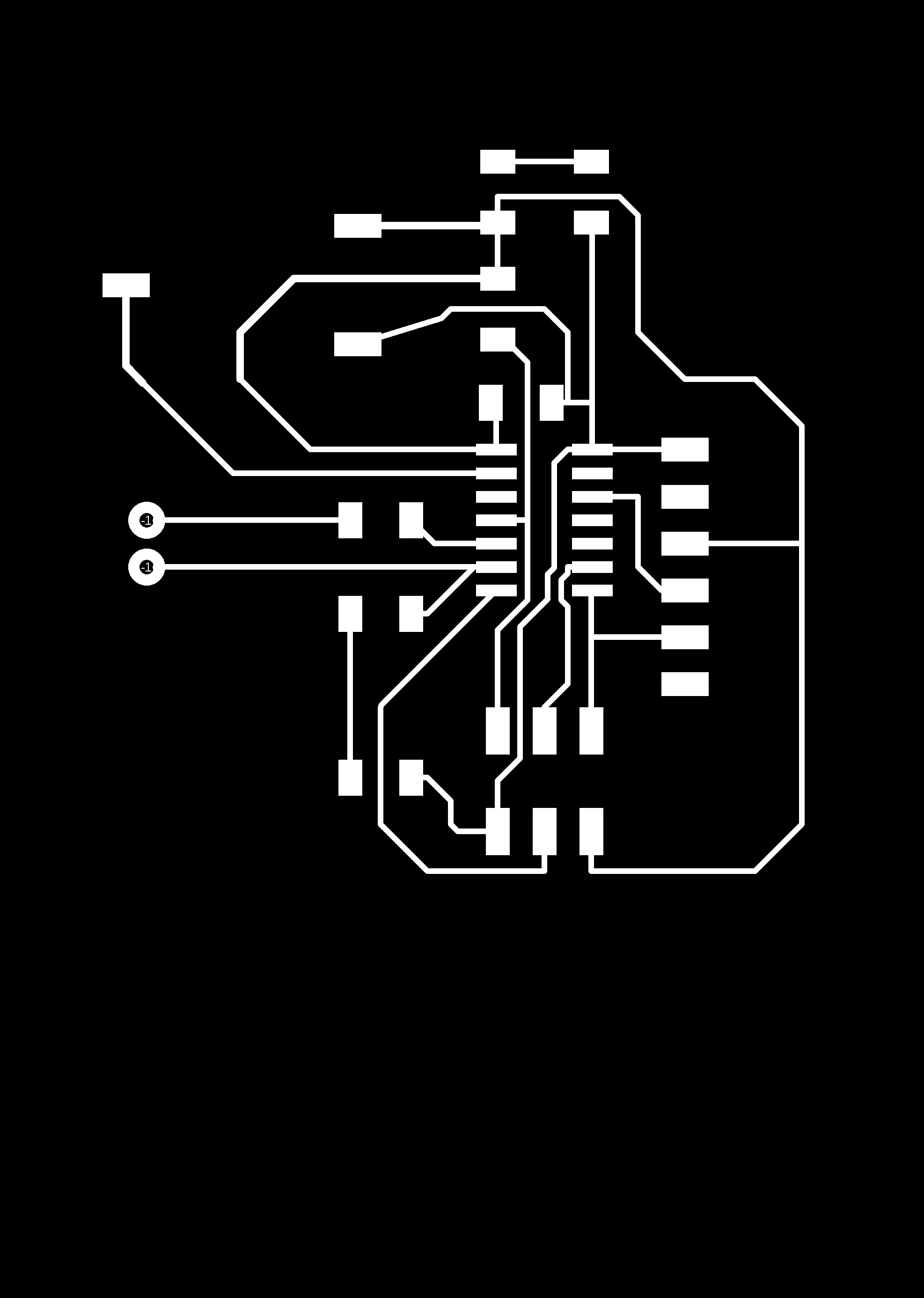
CapSens_45
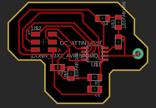
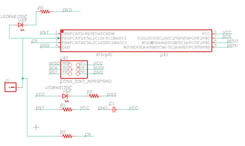
The second board I milled was much simplified from the one before as I took the potentiometre out of the equation. This was instead based on the ATtiny45 microcontroller.
This board was meant to use a LED to output the informations received by the sensor, as this board did not present a serial port.
Unfortunately I also made the mistake here of having my LED placed connected with the sensor, which disturbed the threshold calculation.
In defense of not making a Frankenboard
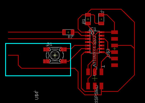
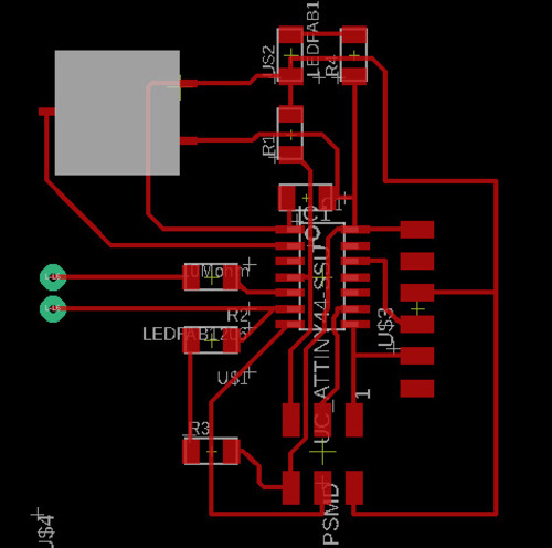
I did some mistakes in the design of this board, as I dont like waste, I should have fixed them in some more or less tidy and more or less creative way, for example creating bridges with wire. I decided to opt for spending more time designing a board that could be used for multiple projects: here is were the fil328 pcb came into existance:
as I was designing a board that would feature the setup for a capacitive sensor (2 connected pins, 1 massive resistor), I added the potentiometre for value trimming, and a button for function experimentation and debugging, and another LED for debugging, I realised that I would have wasted most pins, so I traced the connections ending in through hole pads, that I then drilled and soldered with pins.
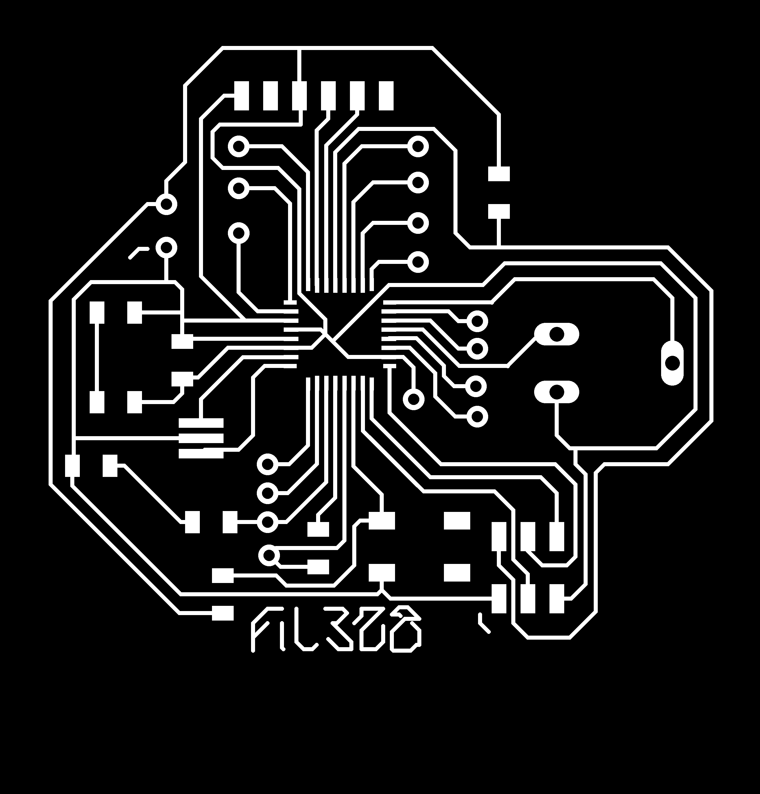
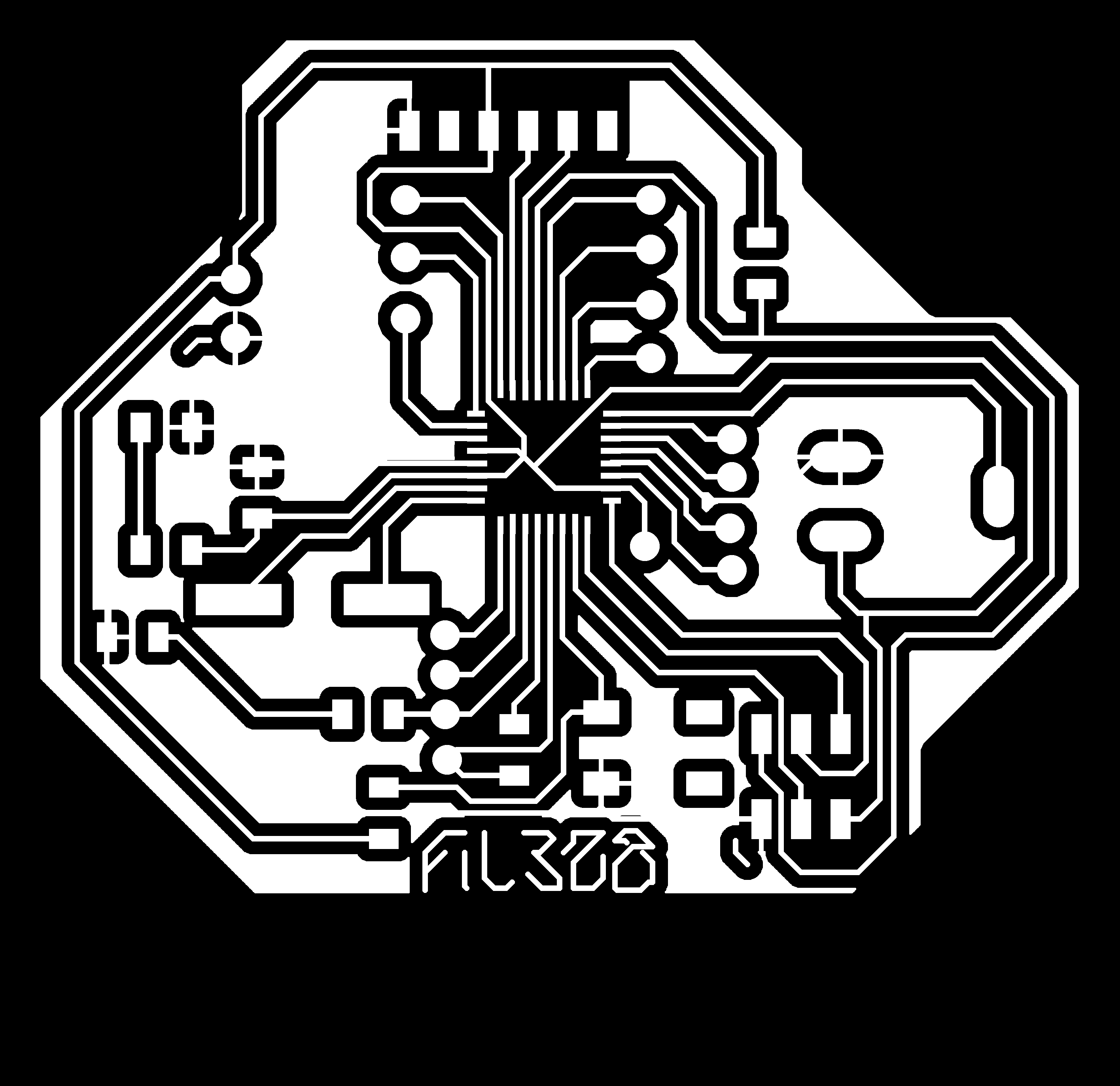
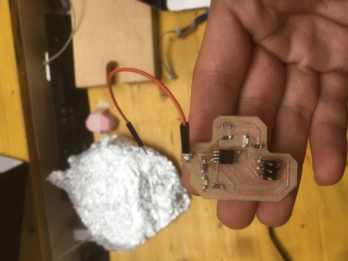
CapSens_328
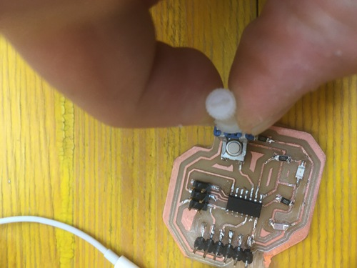
My last iteration in Input Devices was done using the input\output network pcb I later designed and produced. This board featured a series of open input\output pins, and one two of those were specifically routed to be a capacitive sensor.
To view how this board was designed and produced one can visit this link.
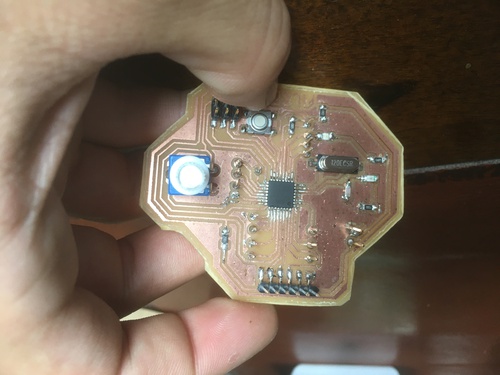
In this final iteration I managed to get the board to sense weather the foil was being touched or not, to communicate that to my serial monitor, and to have a blue led to light up when this happened.
Code
I received a lot of help from my tutor on this week code: it was the occasion for me to come into contact with syntaxes and functions of C++ that I did not encounter before, such has the for() and while() functions, used to reiterate parts of code or to have something happens at the same time as other processes.
This was also the first time I inserted in my code a series of serial communication messages I used to check where the board found itself in the code timeline, and where I needed to debug.
This code worked by sensing multiple times the charge\discharge speed in between the two pins, It then create a average value for this four reading, this would become the threshold value that indicated (wether the charge\discharge times got too big\over such treshold) if the sensor was being tuched or not. The potentiometre was used to trim a bit this threshold value, in order to compensate other current emanations (for example if I was using this board next to my laptop) or some background noise.
I also had prior versions of this code for the 44 and 45 boards.
I believe this code was based on this example by Paul Badger and Paul Stoffregen.
Group Assignment
This week group assignment can be found on my collegue Luisa‘s repo.
Files
CNC files
- cap45_out
- cap45_traces
- cap44v2_out
- cap44v2_traces
- cap44_out
- cap44_traces
- cap44_out
- cap44_traces
- cap328_out
- cap328_traces
Boards
Final code
Prior codes
A lot of these don’t fully fuction, but they can be used to see my progress in coding this sketch
Board PNGS


- works for both following versions