13. Output Devices
This week I worked on designing a mega328 board that i could use both for inputs and outputs. used it to attempt to control a tile of four Neopixel matrixes.
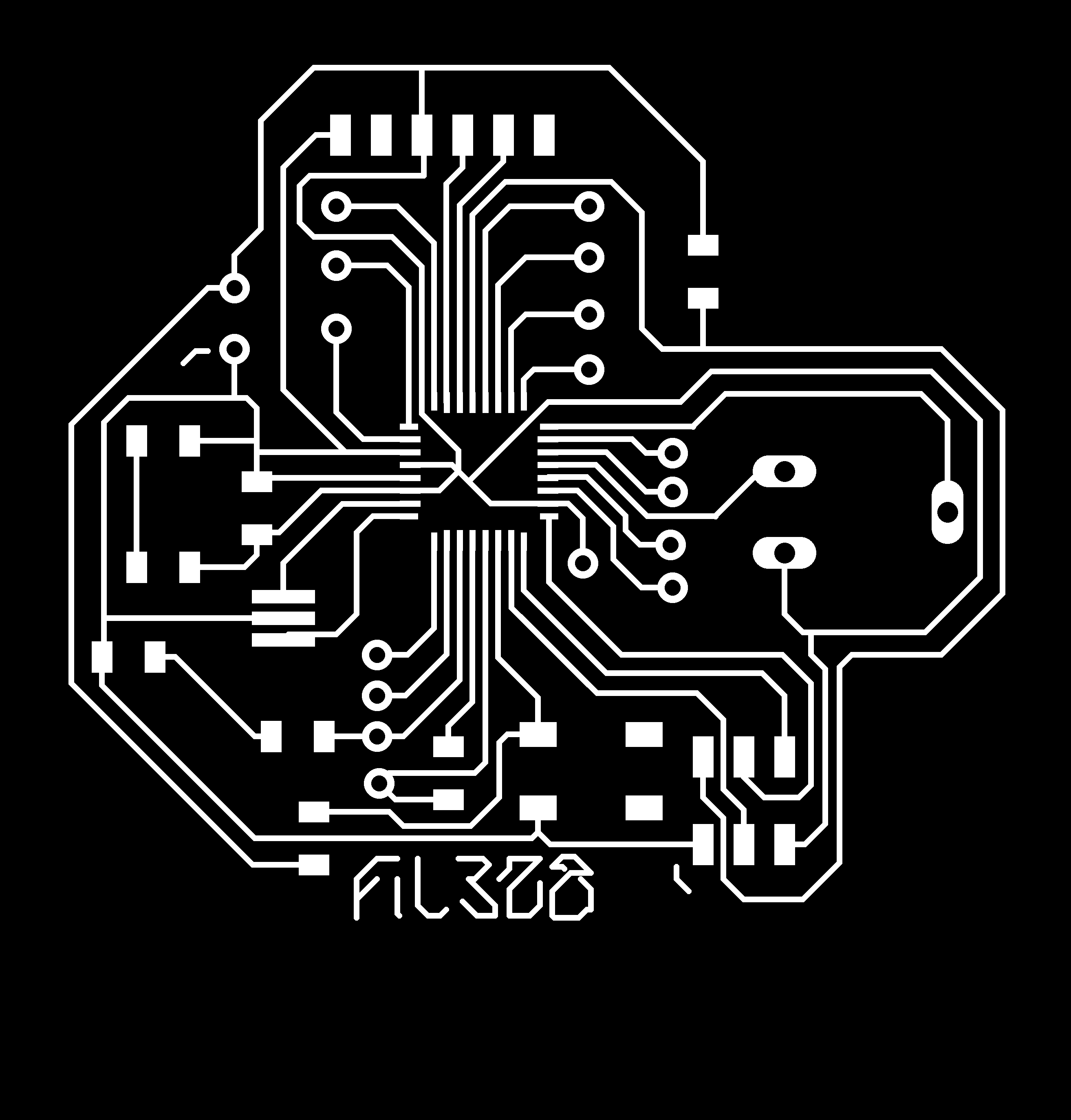
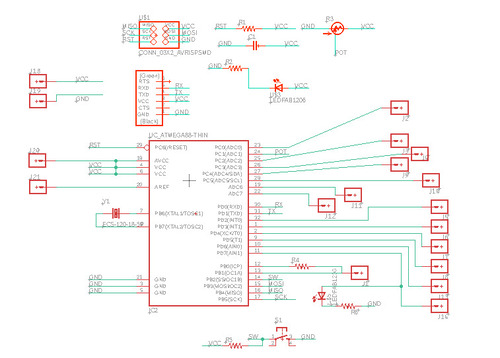
Board Schematics
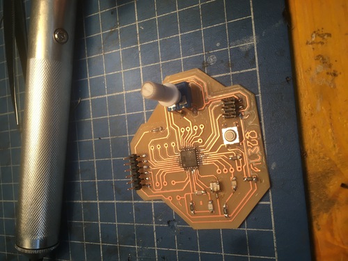
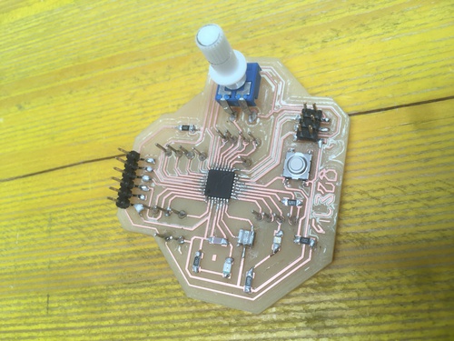
The schematic I designed for the board included:
- a ATmega328 microcontroller
- a control LED between vcc and gnd
- two dedicated pin for a capacitive sensors
- a LED I could use in debugging routines
- a potentiometre and a button that I could use in my .ino
- a vcc and gnd connections are routed so that I could use them for inputs and out puts
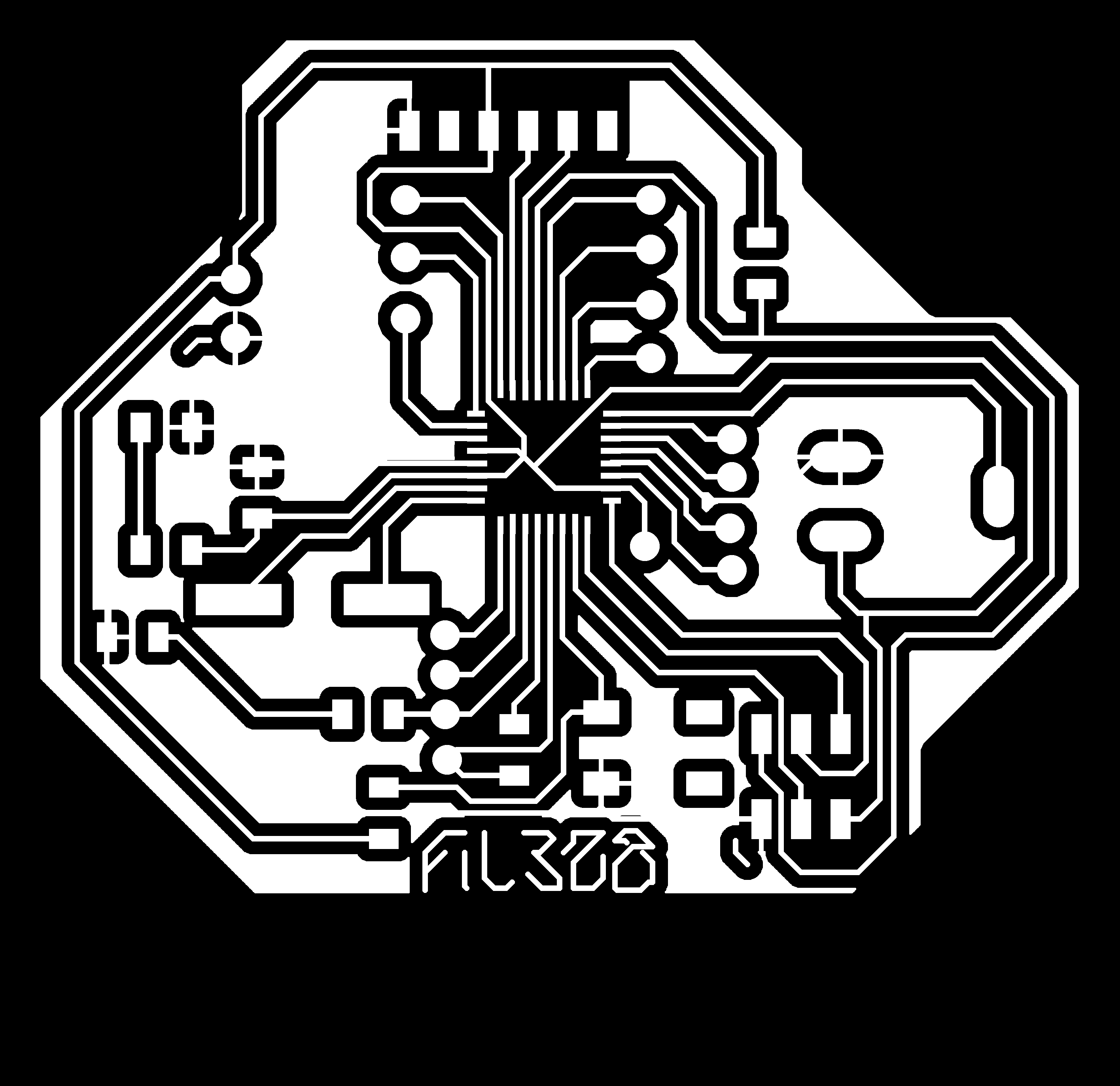
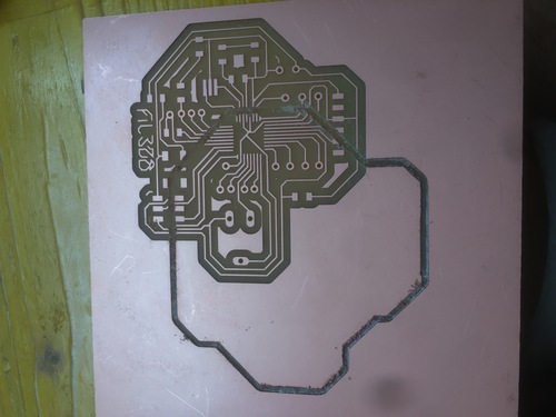
PCB CAM
My board required four different machining processes:
- the engraving of the traces
- a larger diameter drilling for the potentiometer
- a smaller diameter drilling for the rest of the pins
- the outline cutout
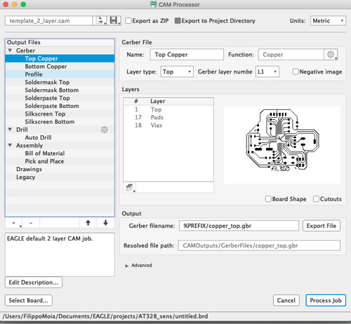
I exported a .dxf via EAGLE’s CAM processor, and also linked my board to a Fusion360 project. I needed this to use the manufacturing workbench on Fusion.
As fabModules is pretty easy to use I decided to use that for the engraving and Fusion manufactore for the rest of the processes.
For the fabModules part of the process I followed the same steps I took before:
- export high res monochrome .png
- adjust size on PS
- upload to the site
- select extension
- select job
- edit job options
- export
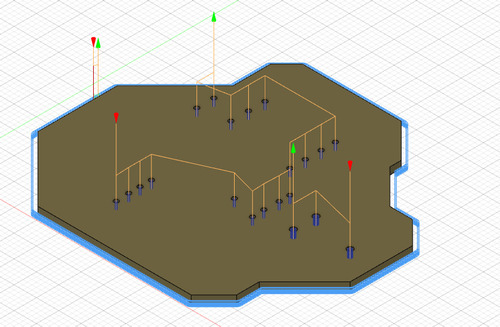
In Fusion I did as follows:
- firstly I set up the stock coordinates and orientation
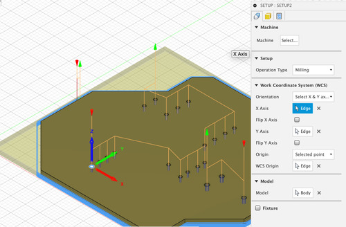
- I then set the home for the drill\mill job in a point that I could easily identify and locate once the engraving was done
The home was set as the first hole closed to me as centring the tool on such hole was fairly trival.
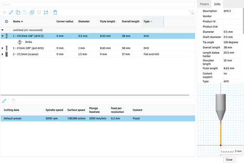
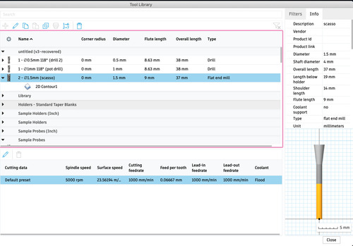
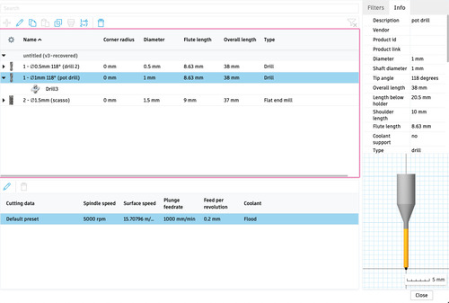
- I created a library for the tools I would be using
- edited such tools
I created three different tools using a caliper to take measurements.
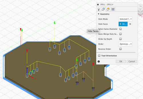
POTdrill
Firstly I selected which faces were to be drilled.
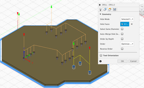
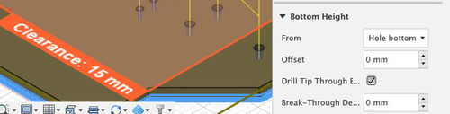
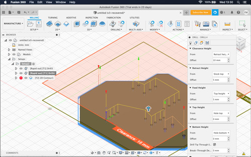
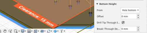
I then selected the different heights and depths.
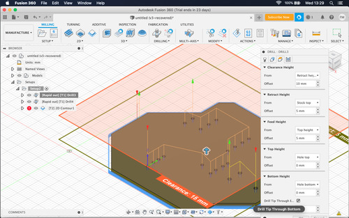
It was important to select this option as it assured identical diameter all throughout the drill hole.
SMALLdrill
The second drill job was pretty much identical to the one above with the difference standing in the tool used and the selected faces.
Outline
I first generated a contour job in fusion.
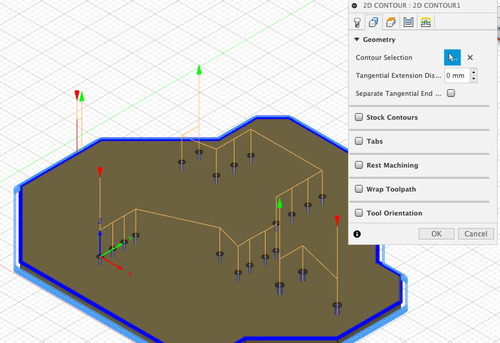
I selected tool and contour.
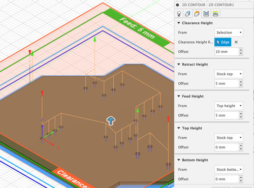
Define heights and depths.
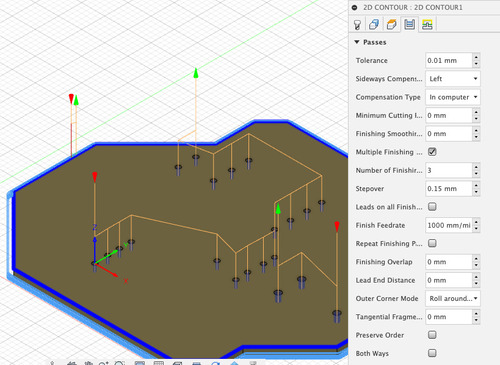
Defined layers and passages.
This job was much slower than the one generated by fabModules and so I thought it was more efficient to stick with the outline job present in fabMoudles, this proved to be wuite quick when I discovered the homes remained intect when switching between User’s and G54’s homes.
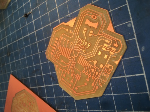
Machining
I thought I would have had issues with the homing system as after the failure with the provile using fusion contour, as I would have had to return to a prior home. The first time I marked my first home by slowly lowering the mill and rotating the spindle so to leave a mark.
Afterwards I found out that as the Fusion generated gcodes are working on the G54 coordinates system and the fabMoudules .rml rely on the User coordinates system, and by switching between the two on the Roland mill both homes would be saved, I could easily switch between the two.
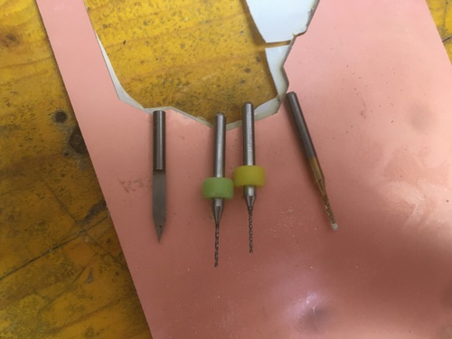
Each of these mill bits corresponded to a different job done on this board.
In this first trial I had an extra 2mm flat end mill used to clean the board from residual copper areas, I did not notice that the path calculation would actually interfere with the trace engraving, factually making this board inoperable.
In a second iteration I forgot to revert in between the different coordinate systems, which effects are easily spotted.
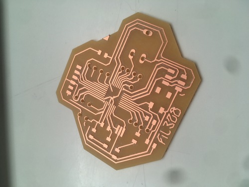
The third time the pcb came out as I wanted, unfortunately excessive use of lubricant caused the dust to “glue” together with the paper layer, causing an unpleasant aesthetic result.
Neopixels
Understanding the functioning of the matrix and tiles was not a easy task, as well as keepig a tidy wiring. After following the Adafruit guide I still had many doubts about the syntax of this library.
At first I tried by breadboarding to more easily change things up.
The first few issues I had were cause by the fact that I had put the wrong kind of LED in my descriptive array.
I then tried to operate on the various example sketches in order to understand how they worked.
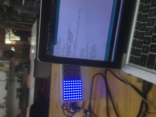
When I felt comfortable in cotrolling my pixels as a strand, I moved onto controlling one matrix, then the 4 matrixes as a tile and at last I iterated on the code in order to integrate all the controls present on my board.
Matrix controlled as if it was a strand.
When I was having issues I spent a useless amount of time testing the connection between each of the LED.
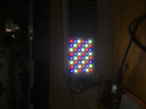
Controlling 1 matrix.
This is what my first issues were like. I found out that connecting everything to a common ground helped stabilize these issues.
Breadboarded version of strand control.
Controlling 1 matrix.
Controlling the 4 matrixes as a tile.
The main issue was that I was trying to control the board as a finite state machine, but having three different kinds of inputs:
- the serial
- my potentiometre
- my switch button
After not managing to utilise all these elements I decided to only use the physical inputs, and have serial only communicating state changes in my board.
The code identifiesdifferent states:
- a safeguard\start state that cleared all the pixels
- a full state in which all pixels are filled with one of the 3 different main colours (controlled by potentiometer)
- a “epilepsy” state controlled by the switch button in which all 3 colours are repeated on a loop (and dimmable with a potentiometer)
Every change of state is communicated to serial monitor.
Video showing all functions.
Group assignment
This week we were to calculate\measure the power consumption of one of our outputs.
We decided to measure the power spent by my LED matrixes.
At their maximum brightness, Neopixels should draw up to 60 milliamps, but generally they are never turned up that way.
Adafruit gives the following function to estimated the absolute maximum of minimum amps needed (at 60mA) and a generally acceptable value (at 20mA).
number of NeoPixels * 20 mA ÷ 1,000 = x Amps minimum number of NeoPixels * 60 mA ÷ 1,000 = x Amps minimum
Therefore, in my case these values would be:
256 * 20 mA ÷ 1,000 = 5.12 Amps minimum 256 * 60 mA ÷ 1,000 = 15.36 Amps minimum
By datasheet each 8x8 Neomatrix has a maximum power consumption of (W): 0.24W x 64 = 15.36W, so that would be for all four (W): 0.24W x 256 = 61.44W.
The formula to calculate power consumption is W(atts) = V(olts) × A(mpere); it can also be displayed as power consumption per hour, being Wh = W(atts) x h(our).
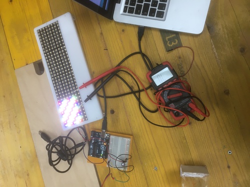
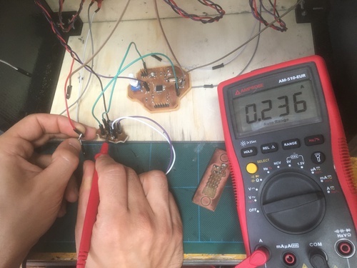
Now, these were all estimates: it is time for me to check physically, using a voltimetre and a bench power supply.
I used the voltimeter with 128 Neopixels turned on, lit in full red (255, 0, 0), at 100 over 250 brightess. I chose this setup as I thought was a good amount of light and power to be well over what I would need in my final project. I interruped the line in between the supply power and the neomatrix VCC, I then used the voltimetre to close such connection, selecting the ampere setting.
The value came out as 0.236A, so
0.236A = 236mA, it was alimented with 5V, so it comes to Watts as 236 * 5 = 1180Watts
So the power usage for hour of my machine can be averaged at 1180Wh.
Files
PNGs

- works for both following versions