6. 3D Scanning and printing
This week I encountered 3D printing and scanning.
I used Fusion 360 to design my model and Ultimaker Cura to generate .gcode files. The machines I used for printing were Ultimaker 2+ and Wasp Delta. I took pictures for the scanning with a small action camera, the softwares I used to generate the scans were Colmap and Metashape.
3D Printing
The whole process around 3D printing is defined by a series of time consuming tasks. Nevertheless, the results of the process can be extremely satisfying, as it allows to think and produce results that are hardly achieved by other fabrication processes.
Machine Characterization
The first step in this week assignment was to understand a reproduce the workflow around the machine and to test its capabilities.
The first thing we did was to:
- turn on the machine
sounds trivial but I couldn’t find the switch on the Wasp Delta.
Afterwards I learned how to load\change material on both machines.
This is the workflow for the Ultimaker 2+:
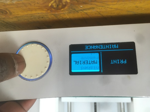
- select: Material
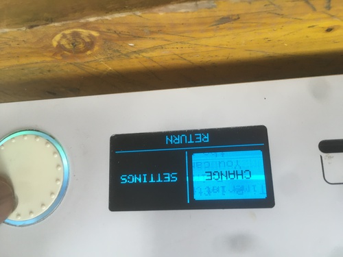
- select: Change
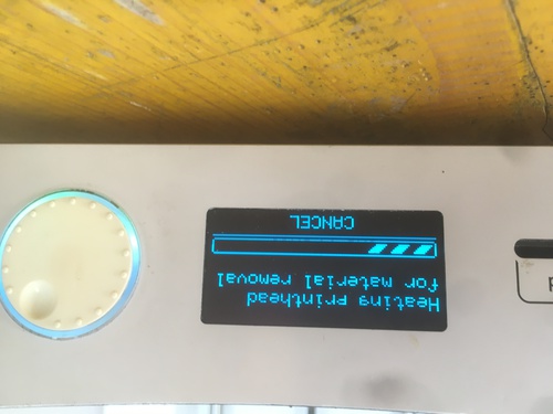
- wait for nozzle heating
- manage material roll so it doesn’t get tangle as it unwinds
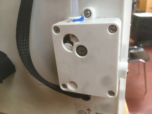
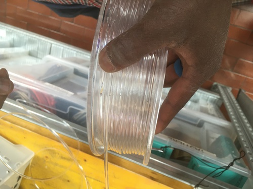
- press the lever to open the forwarding mechanism to fully extract the material
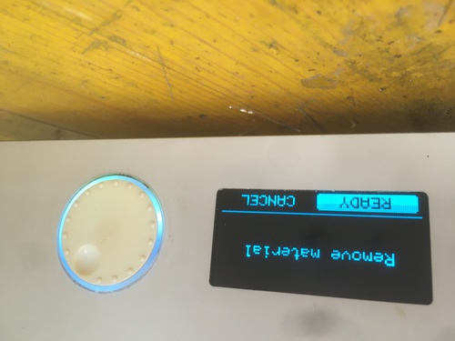
- select: Ready (under Remove material)
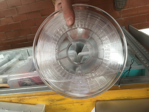
- secure the material onto the roll
In order to load new material the workflow is very similar:
Once the previous material is removed you can begin loading the new one
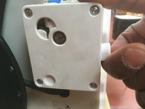
- insert the end of the material in the forwarding mechanism
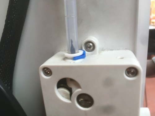
- press the lever to open the forwarding mechanism to allow for it to “catch” the material
- wait for the material to be forwarded for a few cm
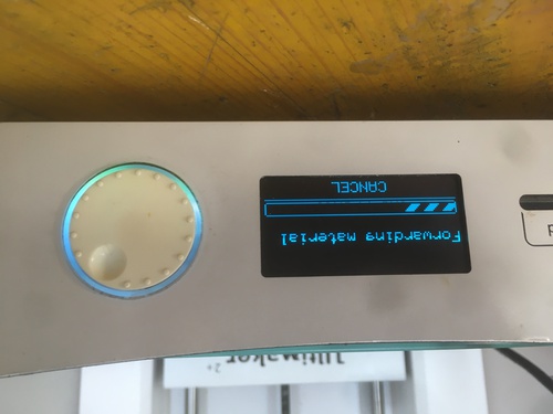
- select Ready for the machine to forward the material quicker
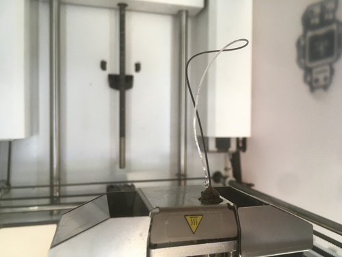
- wait for the material to be extruded by the nozzle
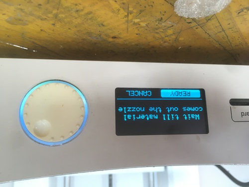
- once a visual analysis show that the material is extruded without traces of the previous material, press Ready
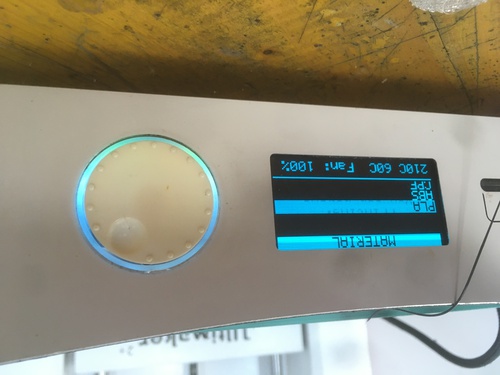
- Select what material has been inserted for the machine to load the specific settings
The roll of material can be both placed onto the axis mounted on the back of the machine, or onto its specific rails in case the roll is too big.
The process for loading and changing material on the Wasp Delta is fairly similar. The sole difference stand in the fact that the formarwarding mechanism is not motorized.
- Select: Prepare
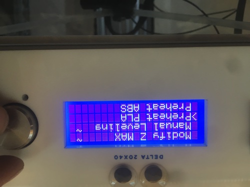
- Select: Preheat PLA (or ABS)
- Once the material begins being extruded, start rewinding the material with the lever
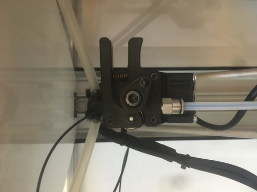
- Open the forwarding mechanism to release the material
- Secure the material onto the roll
In order to load new material:
-
Insert the material into the cavity on top of the machine
-
Open the forwarding mechanism for it to “catch” the material
-
Select: Preheat PLA (or ABS)
-
Actuate the lever of the forwarding mechanism untill the material is being extruded by the machine
-
Once the material (after visual analysis) is extruded cleanly, the machine is ready to print.
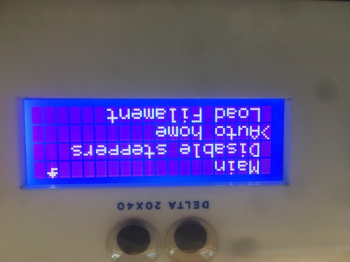
- Select auto home to bring the machine back to it’s orginal position
The following steps were done to test the capabilities of the machine.
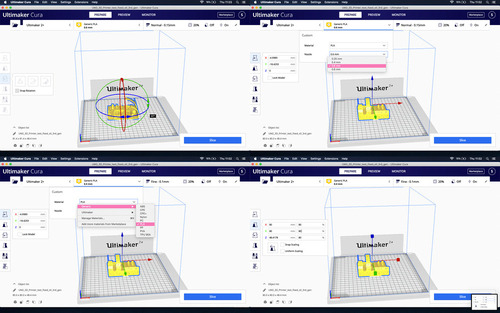
The steps to take to get the machine printing on Cura are:
-
select the machine
-
select material and nozzle
-
select the fine tuning options
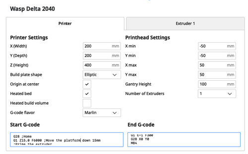
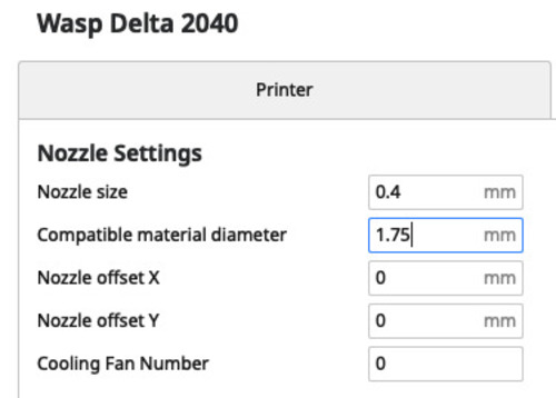
Beacuse Ultimaker Cura does not support the Wasp Delta natively, I added this machine to my printers setting up the correct parameters.
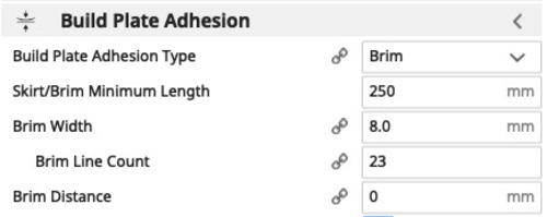
Every model I printed (aside from Benchy) was attached to the plate with the same Brim options.
Technical specifications
The two machines present a series of differences as shown in the following table compiled by Raji.

Also:
- the Ultimaker moves on 2 axes, while the WASP moves on 3 axes, in delta movents;
- changing the nozzle on the Ultimaker solely requires to unscrew it, while it is necessary to change the whole moving body for the Wasp
- the Ultimaker works with 2.85mm filament while the WASP works with 1.75mm filament.
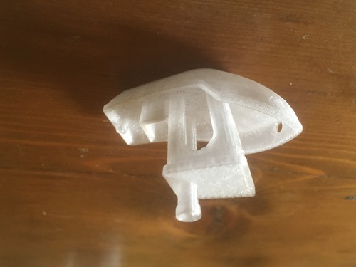
Benchy
We downloaded the model for the “Benchy” test. The model was printed using the Ultimaker 2+.
Benchy is to be printed unsupported. The result was fairly good in terms of quality: it only presented a few slight mistakes on the top of the arches and windows, and underneath the roof.
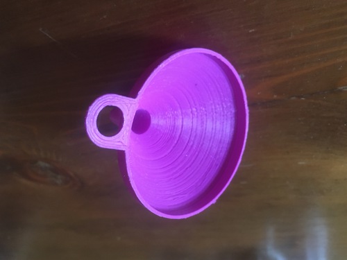
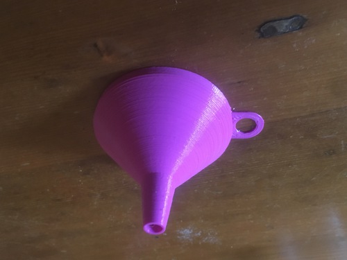
Funnel
We printed a model of a funel (designed by my tutor Antonio) on the Wasp Delta. This model was also printed without supports and didn’t present any mistakes in its final form.
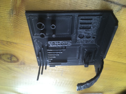
Printing Test
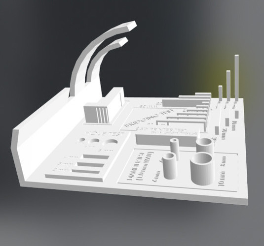
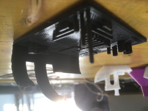
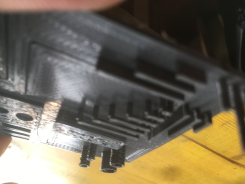
I decided to download a “torture” test model from Thingyverse to speed up my process of characterization and to have a go with the Ultimaker Cura software.
Link to the 3d printer test.
This tortute test presented a series of features to be printed without supports:
-
overhangs at different angles
-
bridges at different distances
-
holes of various measures
-
pipes of various diameters
-
towers and walls
In order to save time I chose a series of options on Ultimaker Cura designed to finish the model quicker:
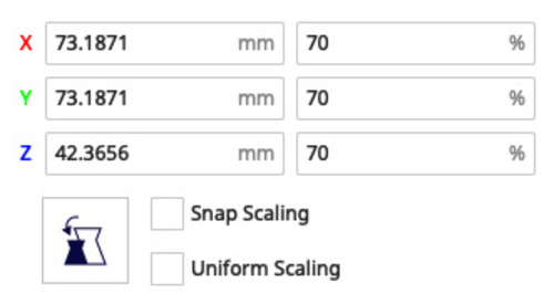
- first of all I downscaled the model
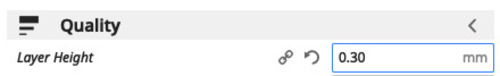
- selected a fairly high layer height
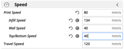
- selected a higher printing speed
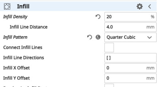
- reduced the infill density

- selected a thinner wall thickness
I therefore manage to massively reduce the printing time.
Original printing time.

Printing time at 80% scale.

Printing time at 70% scale.
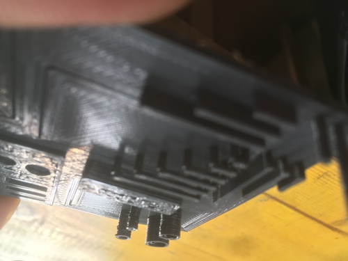
Because of the options I chose to selected, the final print was not presenting its optimal features (especially in aesthetical terms), it did give me a good overview of the machine capabilitiels nonetheless.
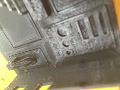
Even with such settings:
-
overhangs were printed with no problems up untill 55°
-
bridges, walls and towers did not present problems
-
the diameters were respected, with the sole difference of small filament residues in the larger ones
-
circular holes did not present problems
-
elliptic holes tended to “close up” at the extremities of the smaller ones
-
the typography did not came out properly (mainly because of the downscaling)
-
the unsupported bracket fully failed
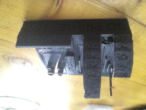
This test was very helpful to fully understand how to design my model for the week assignment.
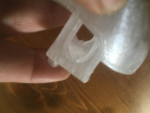
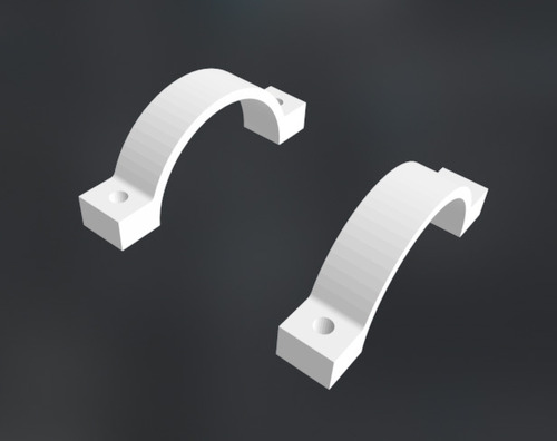
Garmin Quarter Turn
Because I didn’t feel capable enough with Fusion360 to design the Garmin quarter turn interface, I decided to download this model from the internet.
The model for the interface was found included in this design.
I designed my Garmin mount so that the quarter turn interface was to be glued to my mount: I did so to specify that it was designed and printed separately and not to take merit for something I didn’t do.
I printed a first version at 100% scale on the Ultimaker 2+.
This first model had a baggy fit with my Garmin device.
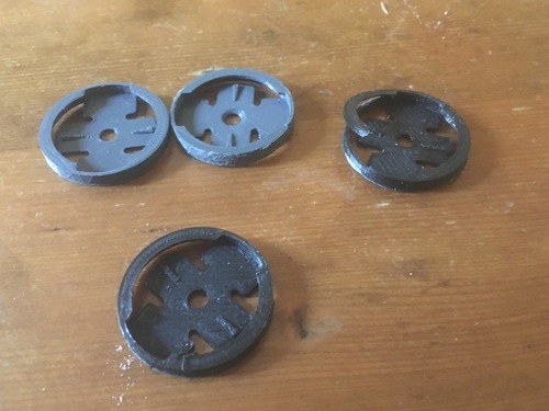
I printed a series of 4 more interfaces with incremental downsizing.
The second version had a better fit, but still a bit baggy, especially after a few try, when the PLA got slightly deformed.
The third and fourth version had a very tight fit.
The last version was too small and broke once i tried it.
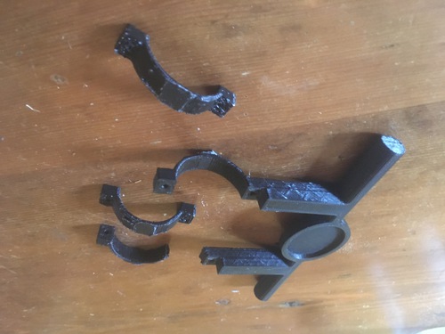
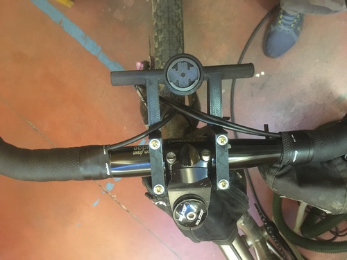
My Model
A few months ago I found a Garmin GPS device in a forest. I wanted to get a mount for it but i found none that was both satisfying in terms of functionality, fit with my bike, added functions and price.
In more specific terms I wanted one that:
-
presented double link with the handlebar for structular strnght and to generate a larger surface to attach stuff with elastic cords
-
presented a cilindrical shape to attach lights
-
presented enough room to manage\tidy my brakes and gear configuration
Design & Analysis
The first design I modelled had a series of issues:
-
the bracket height was to small, causing one to snap almost straight away
-
the cilindrical shape was too narrow to fully support my lights
-
the space left to attach the Garmin interface was too flush (as I did not take into account the PLA expansion)
-
there were too many supports.
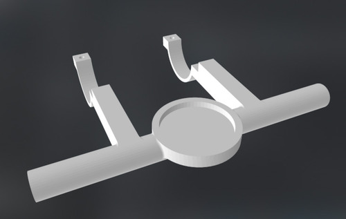
I adapted my second design by:
-
expanding in size almost every feature
-
adding a tolerance paramenter to add to the holes and interface to account for PLA expansion
-
I switched my holes from M3 to M4 to ensure higher structual strenght
-
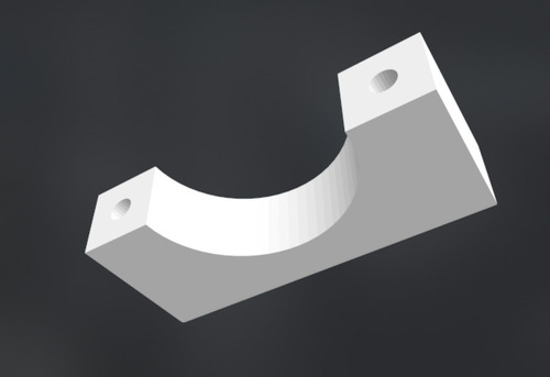
changed the way my brackets met to simplify the way they were joined
This model still presents a series of issues that I’ll solve in a version-to-come:
-
better bracket interface
-
more elegant shapes
-
less useless spaces
-
optimization for shorter screws
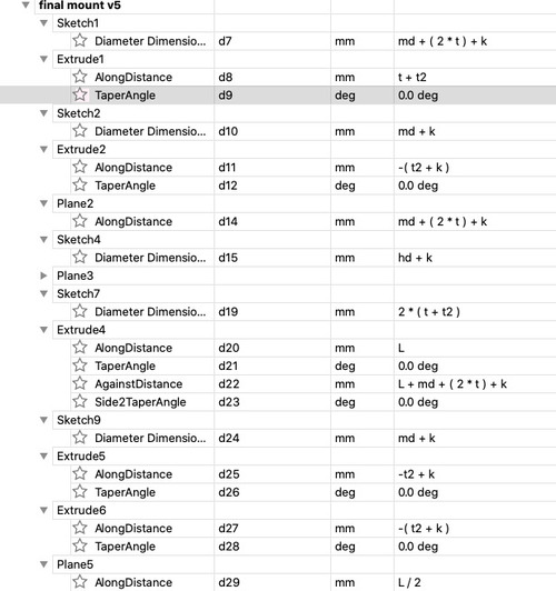
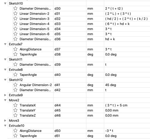
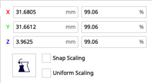
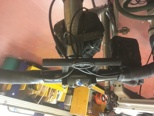
Both my models were entirely parametric, so to be able to adapt my design to verious handlebar designs and standards.
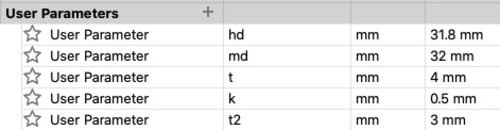
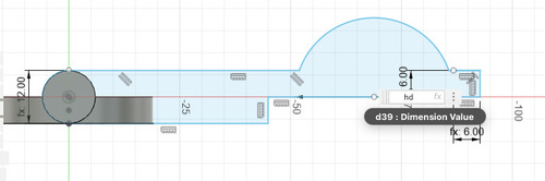
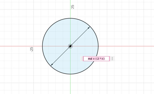
Example of parameters usage.
Further development
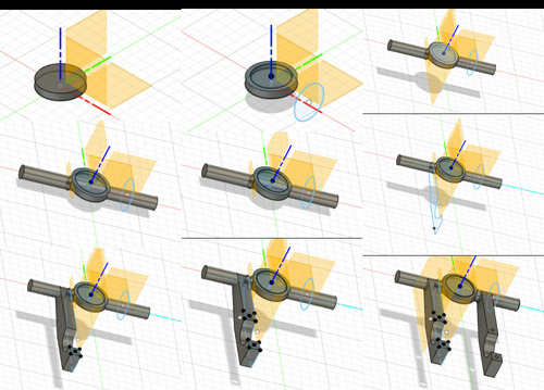
I add here the video showing the design steps utilised in further versions of my mount: the consequent iteration of my design presented sturdier shapes and better use of infill and support settings.
- first model
- second model
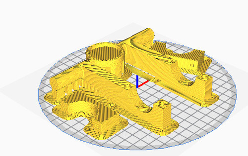
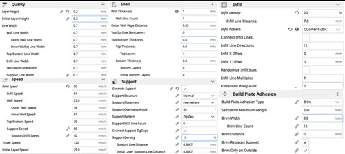
Print File
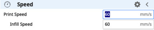
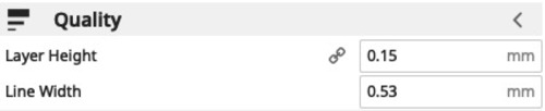
I knew my first model was solely a prototype, so (as I did for the torture test) I decided to select options on Ultimaker Cura that would quicken the process.
These options included:
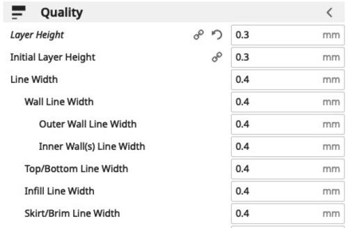
- higher layer height
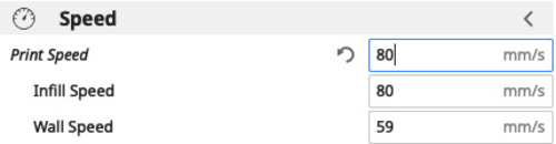
- quicker printing speed
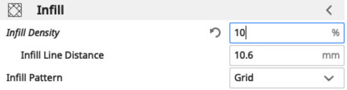
- reduced infill density
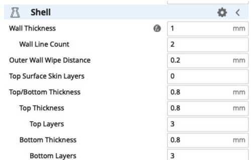
- reduced wall thickness
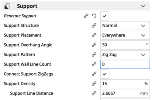
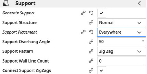
These were the supports options.
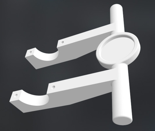
The second model was overall printed with the intent of better looks and higher structural integrity, which both resulted in success, but it took almost twice as much for the model to be printed.
Both my models were entirely parametric, so to be able to adapt my design to verious handlebar designs and standards.
For the second model I lowered the printing speed and layer height to obtain better quality.
Result of first model.
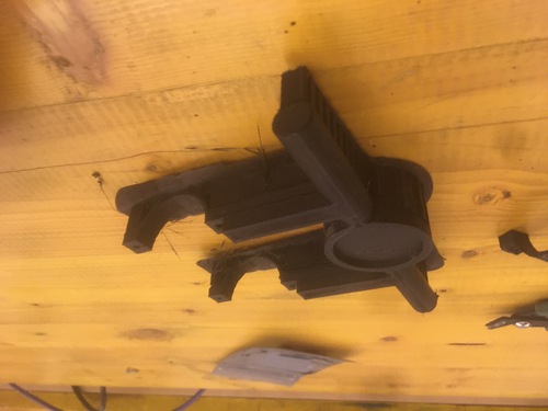
Result of second model.
My designs were ideal for 3d printing as the presented multiple planes, overhang features and rounded shapes that could only be achieved subtractevely only with machines working on more than 3 axis.
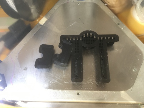
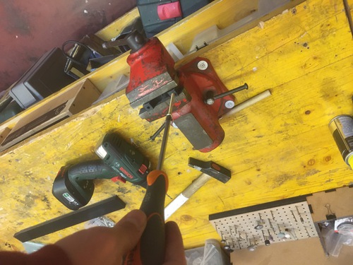
Post Processing
In both cases (after removing the model from the printer’s plate) I gently removed all supports. Secondly, I used a small file and sanding paper to do some deburring, I also used a blade to shave off the remains of the supports.
In my second model I also had to drill through a couple of holes as I mistakenly placed supports in there too.
This is where I did my mistake with the supports: I should have selected “Touching the Plate”.
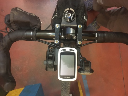
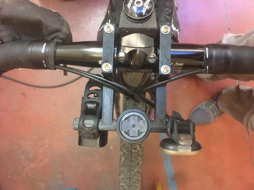
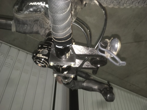
Assembly
As the first model broke almost straight away I didnt get to try and assemble that one.
The second model was placed on my bike using fairly long M4 screws and bolts.
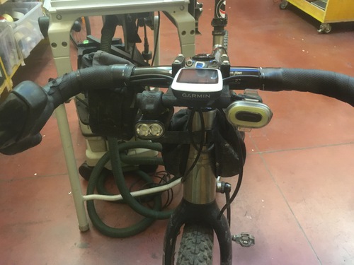
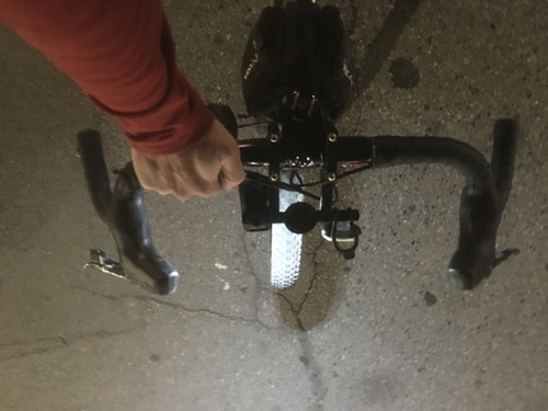
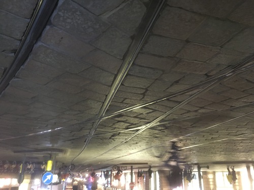
Stress Test
My main worry for the Garmin mount was that i thought it would rotate around the handlebar, I decided to take the bike for a spin on the famously bumpy Milan’s cobblestone roads. Even after a few kilometrs of strong vibration and hits, the mount did not move.
Scanning
I did not expect so, but scanning was the hardest part of this week assignment.
I tried a series of software and took a series a series of photoset, I did not manage to get the right results. Therefore I ended up resorting to use a mobile app.
Sense 2
I at first tried to use the 3D Systems Sense 2 handheld scanner, but since this model has been long discontinued, it is not supported anymore by their own software. What a pity, it looked like a powerful machine.
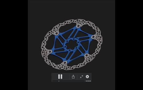
Video Experiment
I started with an experiment: I screengrabber a video of a 3D model that I had rotating.
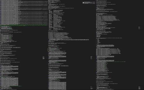
Afterwards I extracted frames from this video using ffmpeg, those would become my photosets.

This was the script I used to extract 24 frames per second. Since it generated too many images, I later went down to 2 frames per second, and eventually to 1 frame every 2 seconds.
I then installed Colmap via terminal.
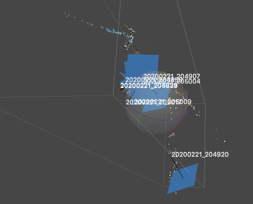
I used the Colmap GUI to have it analign and generate models from such frames.
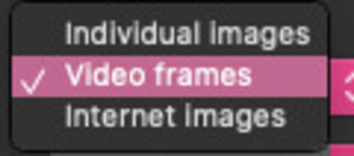
I selected videoframes, and chose the wide angle when calibrating the camera in Colmap.
I did a few tests and it never worked: I suppose because the 3D model did not have anything in the background.
Photoset Test
As I was worried that I was not using the software correctly i decided to download a photoset that I knew somebody else had used to correctly generate a 3D model.
COLMAP
I fed the photoset to COLMAP and it did work vey well, I therefore decided to download a new software.
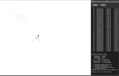
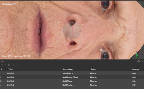
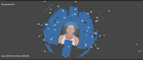
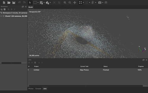
Metashape
When I started using Metashape I realised that it was probably much more powerful than Colmap: computation was much quicker, the final result was in very high definition.
Since I was now confident that I would obtain good results with Metashape, I started taking pictures of the object I wanted to scan in: one of my old ATAC pedals.
Unfortunately I encountered a few problems:
-
the camera I used had a very wide angle, distorting the image
-
the camera did not have manual focus, and it generally struggle with focusing on the object
-
I could not control the aperture to control the field
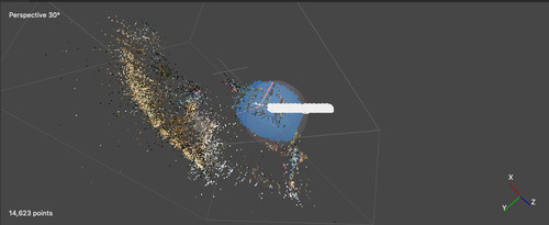
After a few tests that failed I decided to resort to my last choice.
Qlone
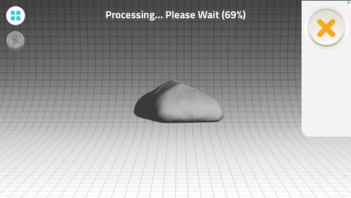
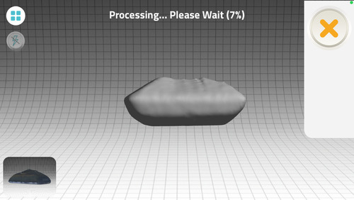
I would have preferred to not use my mobile device, but as the time passed I decided to use Qlone.
I printed the .pdf with the base mesh, placed my object and started scanning.
I opted to scan my Garmin GPS as the pedals were not being scanned properly.
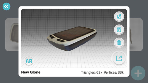
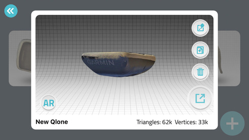
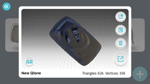
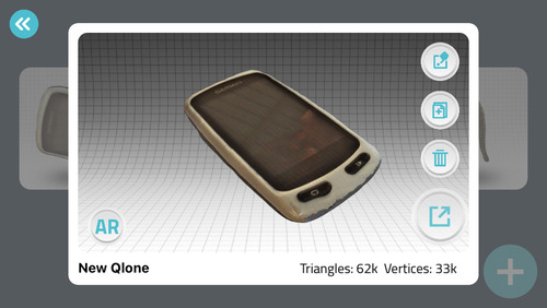
Unfortunately I could only donload the 3d model of the scan if I payed for the full version of the app which was quite expensive. I therefore do not have at the moment a file for my 3d scan.
Files
Task list
-
[x] Characterized Printing machine
-
[x] Printed tests
-
[x] Design 3d Object
-
[x] Print 3d Object
-
[x] Scan object