9. Embedded programming
This week I worked on embedded programming.
I worked on the Hello.board I designed and produced during the previous weeks and programmed with a series of softwares I copied from examples, wrote myself and wrote by my tutor (in order to learn new functions I didn’t previously encounter).
All my programming was done with Arduino IDE, I also tried the terminal toolchain, but Catalina doesnt seem to appreciate AVR programming
. All the prgramming was done in C++ language, and some of them included Arduino libraries for serial communication.
Since my board was designed based on the ATtiny44 microcontroller, I attempted to read its datasheet, it was complicated for my current knowledge of electronics.
Programming
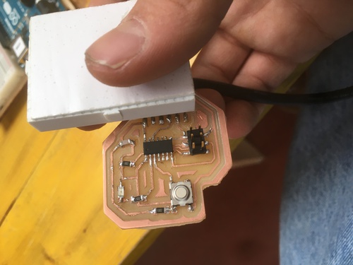
My board presents a few features:
- a LED
- a push button
- a FTDI port
All my software were based on these features. The board was programmed via the FabOptimus ISP programmer.
Setup
The very first steps were setting up my workspaces in orderd to start programming my board.
FAILED: Terminal
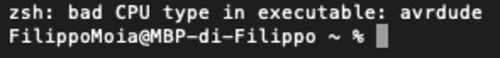
What I did was downloading and installing the latest version of AVR CrossPack. After that I tested in terminal if AVRdude was installed by tipying
This is where I encountered the first issues.
I then installed AVRdude again via Homebrew.
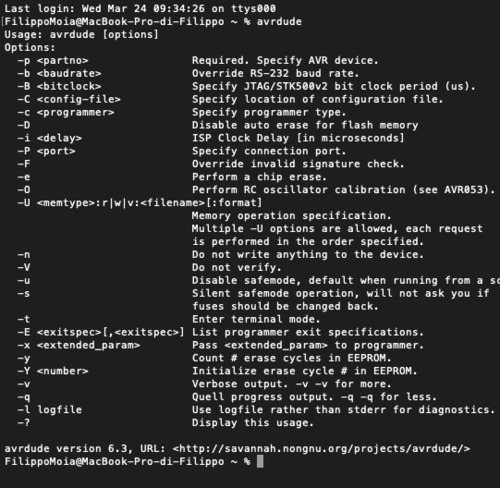
This time
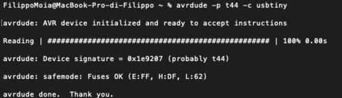
I then interrogated my board by tipying
It was time to test my first program, I chose to start testing with an example code called blinkLED. I modified it’s makefile to fit my board, this included:
-changing MCU -changing F_CPU -changing PROGRAMMER_TYPE
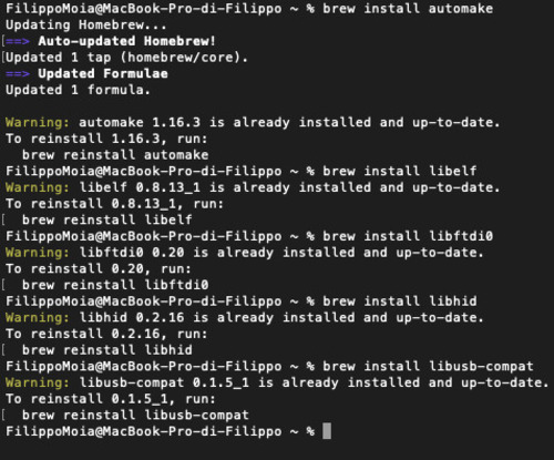
I then opened the directory where I had these files and typed

I checked I installed all libraries needed for AVRdude to work and it seemed like I did so I didn’t really know where to go from here.
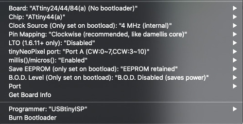
Arduino IDE
Basically the only setup step for getting this environment ready for programming was installing the ATtiny Core library.
All the other setups were in the tool section.
Programming
I had very little experiance with programming as, so far, I only had experiences with the Aerduino starter kit and a few things my tutor showed mt in the previous weeks.
I did a spiral growth so to slowly add functions to my codes.
Void\Loop
I just uploaded an empty page to check my boards were still working, that I connected the ribbon correctly and so forth. All proceeded smoothly. Good.
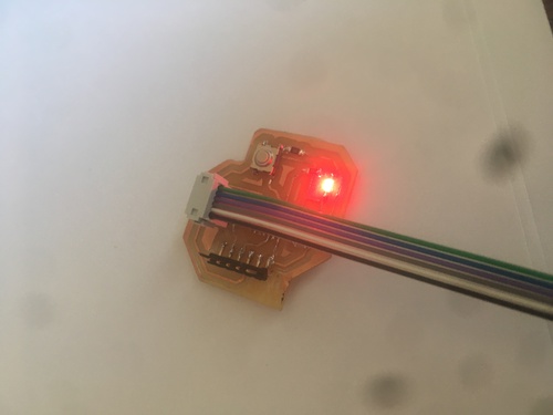
LEDon
The second step was just turning the LED on.
LEDloop
The third code had the LED turning on and off using the delay function.
If i set the internal clock at either 1 or 4 mhz the delay (200) would be at the same speed while if I chose 8mhz it would be much slower.
It would instead be much faster if I chose 128khz.
LEDpush
It was now time I added the button too.
I had a series of variations of this code, for example having the LED blink at different speeds wether the button was pressed or not. All this codes solely included digitalRead and digitalWrite, if\else, and delays.
HELLOmorse
My last iteration of the previous code was having my board photonically say in morse language: “Hello world”.
Serial communication
The next step was having my board to communicate directly with the computer usind and FTDI cable.
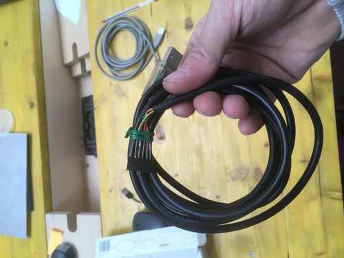
I didn’t realise at first that the cable was routed with a different order of pins than the one of the FTDI connector on my board. When I first plugged it in I almost fried my board, luckily enough as soon as I smelled something cooking I unplugged the board.
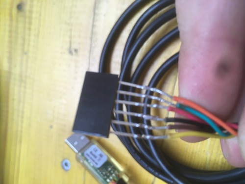
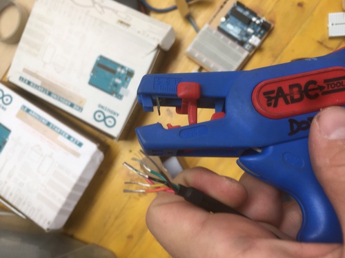
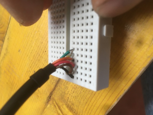
I chopped the male connector, cleared some cable from the plastic, covered it with melted tin and plugged it in a breadboard.
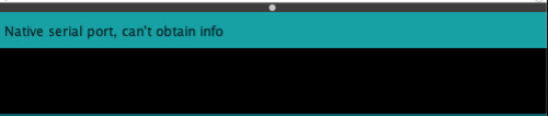
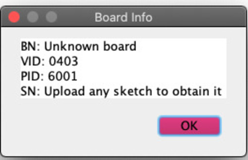
At first I checked the cable was being recognised, but when I tried to get board infos, the computer would not recognise the port.
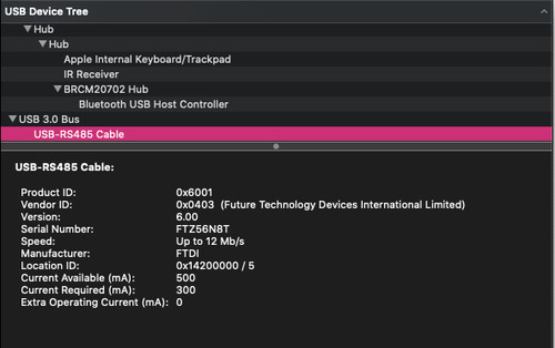
I installed the FTDI drivers, now the board was being recognised.
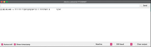
In the first few tests I did I did not write the correct RX and TX ports, and I didn’t include the serial library, so I would get very weird responses from my board.
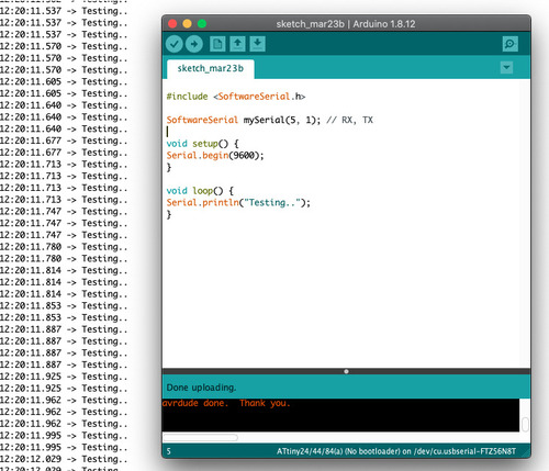
Testing…
The first test I did when I finally understood how to write the variables and setup correctly was an easy ‘Serial.println’ code.
BLINKER_serial
At this time I could include my button and LED in my code. I wrote a code that would turn the LED on as long as I pressed the button, and communicate the state of the LED to my computer.
Further codes
This is were my knowledge of coding language ended and I asked for the assistance of my tutor to write more complicated codes.
My main intentions were:
- to have the board solely communicate the change of state, rather than continously reperating the state.
- to have the LED retain it’s state once I lifted my finger from the board
This is were my tutor introduced my to ‘state’, ‘previousState’ and ‘bool’
blinker_oneoff
This software had the board operating as the previous code, but the serial communication would notify solely of the change of state rather than the state itself
soft_Switch
This was so far the code I would have wanted to achieve for this week assignment:
- the button now function as a switch (in software)
- the LED retain its state once the finger is lifted
- the board communicates the change of state, rather than it’s state
Datasheet
I am currently still in the process of reading and trying to understand the Datasheet, I am doing this in parallel with the book Make: AVR programming written by Elliot Williams. I find it quite hard to fully understand what I am reading. I added a few schematic notes in the next section.
Datasheet
A few months have passed… and I… I read parts of the datasheet of Atmel’s microcontrollers family.
As I did more projects using an ATmega328, that is the micontroller whose datasheet I went through.
First of all, I discovered that there are several versions of such datasheet, ranging from a very synthetic one of 25 pages (mainly enumerating the pins and their description, the register summary and the instruction set), and some of several hundreds pages. Furthermore, different versions of the same chip may differ quite a lot, making it necessary to have additional datasheets for each one of these.
This is the datasheet I went through.
The first couple pages quickly outline the main features of this microcontroller and it’s family. Then comes the table of contents and index.
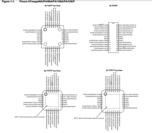
The very first chapter is very useful: it contains a map of the microcontroller’s pins and their description.
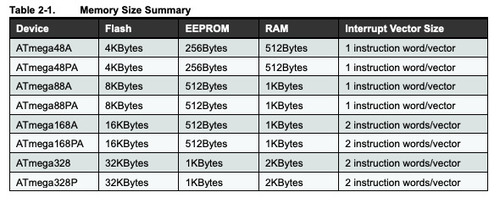
After that, the following chapter is about memory registers, I did not understand much of it, but I did find this useful table were al the various 328 models are compared in terms of memory.
This structure became obvious the more I skimmed through the gigantic .pdf: I did not understand most words, but got from data tables some informations I could process.
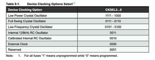
For example the various clock sources options available in this table.
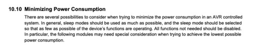
Another interesting bit was the section\chapter regarding power consuption and ways to reduce\minimize such consumption.
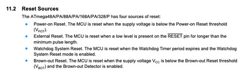
These are the possible reset sources of the 328 family.
Something I found quite hard regarding these datasheets is that I got used to talk with and about microcontrollers in the language I have been using to program them, while in the datasheet they are described in their native language that I do not understand yet.
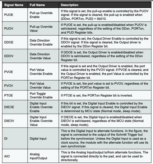
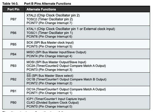
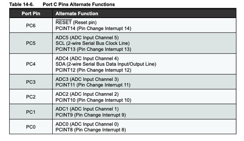
The various tables about alternate functions of pins were also quite useful.
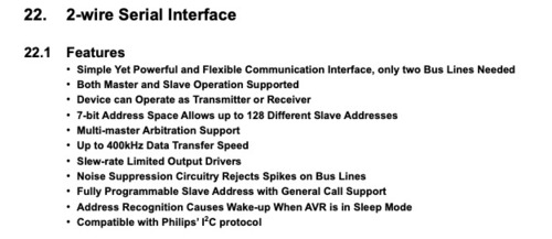
I also read the section regarding i2c protocol as I will later use it in my networking assignment and in my final project.
Different Architecture
In order to test out different programming workflow, I tried programming a board with a different kind of chip.
My tutor suggested I tried the powerful devboard called Teensy 36.
This is a 32-bit microcontroller with 42 pins, and these are part of it’s features.
- ARM Cortex-M4 at 180 MHz
- Float point math unit, 32 bits only
- 1024 Flash, 256K RAM, 4K EEPROM
- USB device 12 Mbit/sec, USB host 480 Mbit/sec
- 64 digital input/output pins, 22 PWM output pins
- 25 analog input pins, 2 analog output pins, 11 capacitive sense pins
- 6 serial, 3 SPI, 4 I2C ports
- 1 I2S/TDM digital audio port
- 2 CAN bus
- 1 SDIO (4 bit) native SD Card port
- 32 general purpose DMA channels
- Cryptographic Acceleration & Random Number Generator
- RTC for date/time
Setup
In order to be able to programme this board one has to download the Teensy Loader applicaton (if you want to compile and use .hex files), if instead you want to use Arduino IDE, one can download Teensduino in order to run C++ sketches on this board.
Example
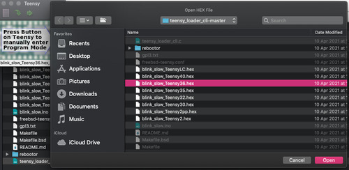
The first thing I did was downloading the directory with all the examples at this link. I then took the .hex file for the 36 version of the board and manually put the board in programme mode by pushing the button.
Sketch
I wrote a simple sketch on Teensduino: this sketch has the board blinking a LED as many times as a single cypher number received via serial communication (cyphers available 1-9).
I opened the IDE, wrote the sketch then I checked all the options under the tool window.
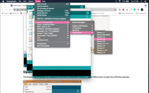
- board is correct (36)
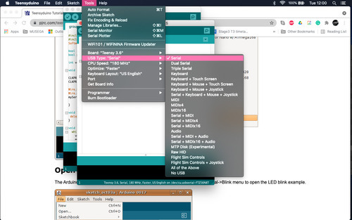
- USB is serial as needed by my sketch
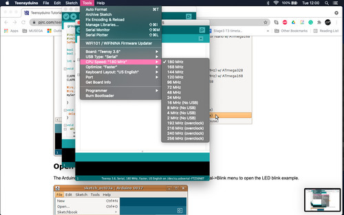
- having programmed much slower boards before I was impressed by the internal clock of this board: 2 orders of magnitude over the 328 internal clock
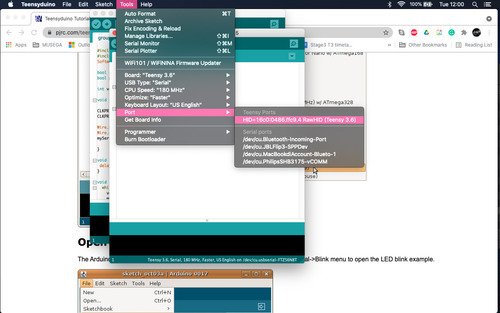
- correct port selected
I then moved on to have the IDE compile and upload the sketch, through the Teensy software I saw the board switch to the Auto programme mode: no button pushing needed when uploading through Teensduino.
Sketch file available at the end of the page.
Notes
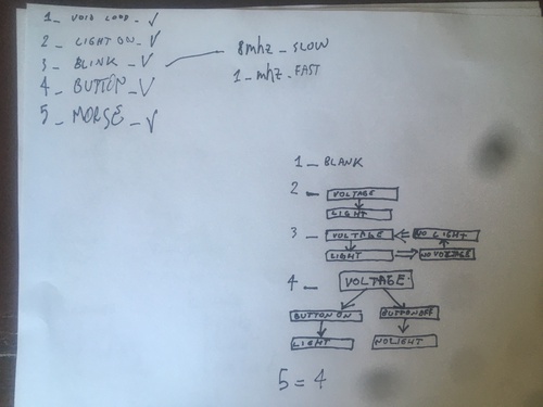
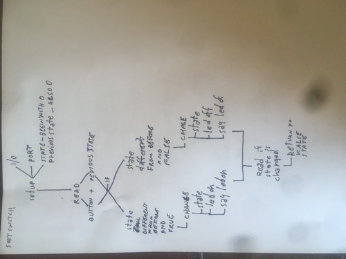
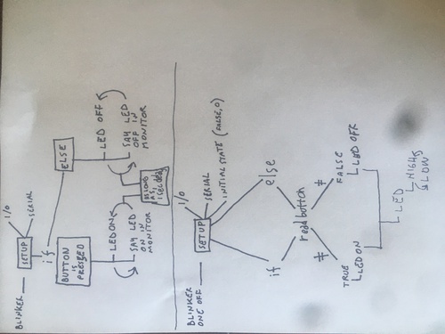
These are the way I rapresented graphically the logic behind the easy programmes I coded this week.
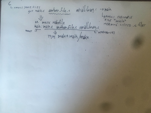
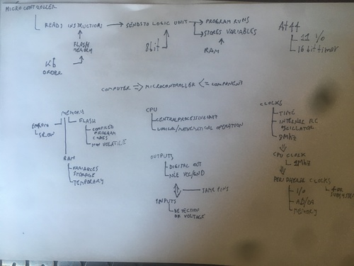
These are the preliminary notes I started taking while reading the datasheet and the book.