Input Devices
GROUP ASSIGNMENT
For this group assignment, which consists of “Probe an input device’s analog levels and digital signals” we are going to use as object to detect a device that Filippo is going to use for his input devices project, since his project contents are more advanced than I am right now.
The selected device is a PCB with a capacity sensor, we could see the signal with the Arduino IDE serial plotter and the oscilloscope.
What does the ociloscope do?
It gives qualitative measures on code wave signal movements , since the electrical current is invisible it’s very important to visualize how the electrical current passes though the circuit. It’s like a multimeter with a display, allowing to visualize how the signal is moving.
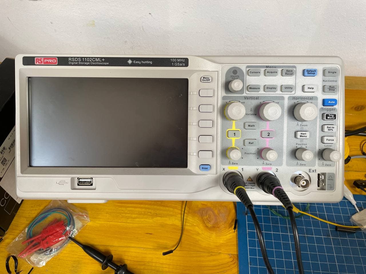
The oscilloscope we have in OpenDot, a RSDS 1102CML+ Digital Storage Oscilloscope, has a digital monitor display. The ray of electrons coming from the signals trace the lines on the monitor.
The horizontal lines of the squares represent time and the vertical ones the tension, so the graph displays the tension passing through the circuit in time.
In the buttons of the oscilloscope there is a wheel that sets the volts by division, and it’s possible to change the position of the signal moving the Y wheel of the oscilloscope using the AC mode, while the OC mode stays on the 0 level of the monitor.