Week 3:
Computer-controlled cutting
Finally we get to use the machines!! I have been looking for this moment, since the start of the course. I already been using some similars to the ones we have at the Lab, but they were not even close to the quality of the ones we have now.
Hopefully this week I will be able to start building and crafting simple products. I believe this week extra assignment is to get to know as many machines and techniques as possible. That will provide me with some basic knowledge, that might be super useful for next several weeks.
The three assignments for this week are:
Group assignment:
• Characterize your lasercutter's focus, power, speed, rate, kerf, joint clearance and types.
Individual assignment:
• Cut something on the vinylcutter.
• Design, lasercut, and document a parametric construction kit, accounting for the lasercutter kerf, which can be assembled in multiple ways, and for extra credit include elements that aren't flat.
Group Assignment
Before starting week this week's major activity, we should characterize our machines. We had to do that in order to get to know the machines and understand the major costumizations and settings.
All the colleagues have worked together to make the group assignment go ahead, but all of us have documented separately. If you want to see other opinions I link to their pages as a group assignment page
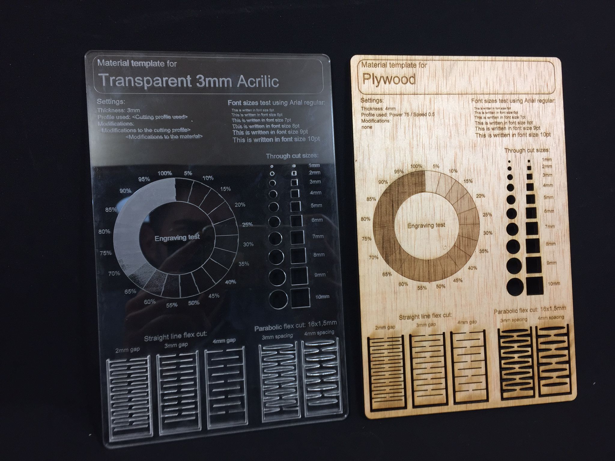
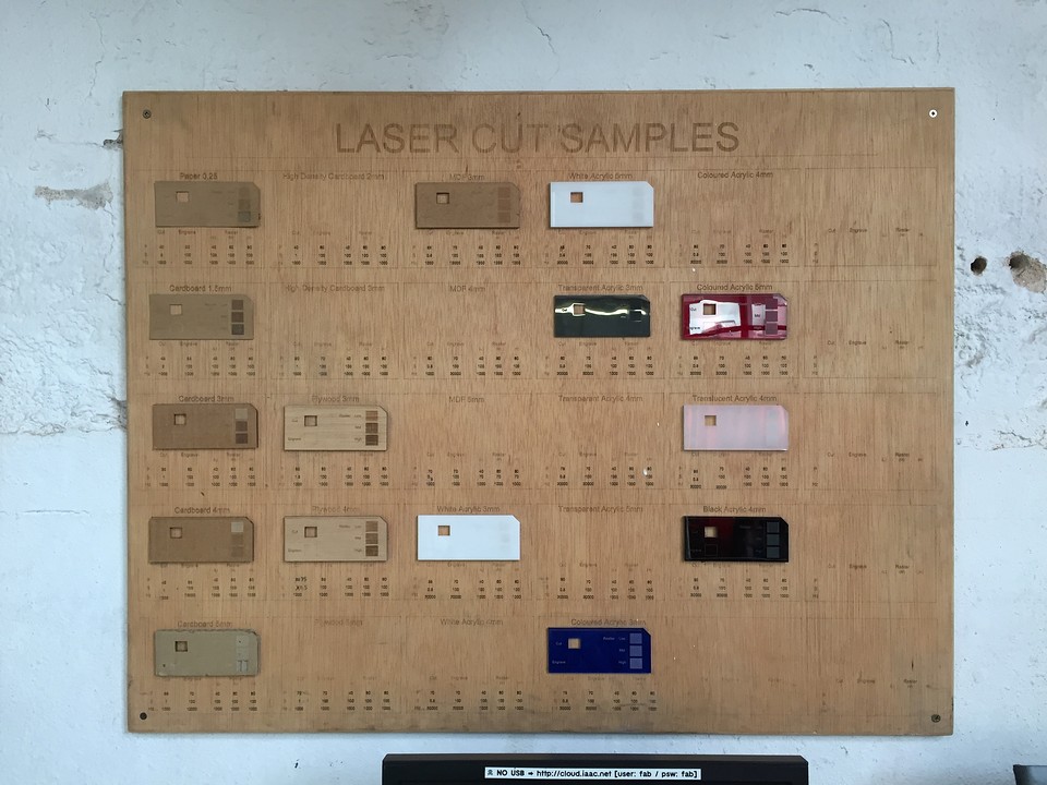
Instead of doing the same tasks individually, we organized into small groups to test various materials and how each one behaved on the laser cutter. Diego and I decided to test the materials we wanted to use for our weekly assignments: he used MDF (2.5 mm) and I used transparent acrilic (3mm).
While talking to Josep, one of our instructors, he told us about a datasheet test he had developed during his Fab Academy 2019 experience. So we jumped into Github to find his repo and download the file. We thought it was an amazing work and as Neil says: "Don't start from scratch".
So, once we had the file properly charaterized for our materials and softwares (Rhino, because the laser cutters we have at IAAC use it.) we went to the laser cutters room. There we joined Josep who guided us through the process of working with this machines. The main steps to work with this machines are:
- Step 1: preparation
-
Prepare your files to be cutted, export your files in the proper format or in our case, upload it to our cloud in .3dm, the default extension from Rhino.
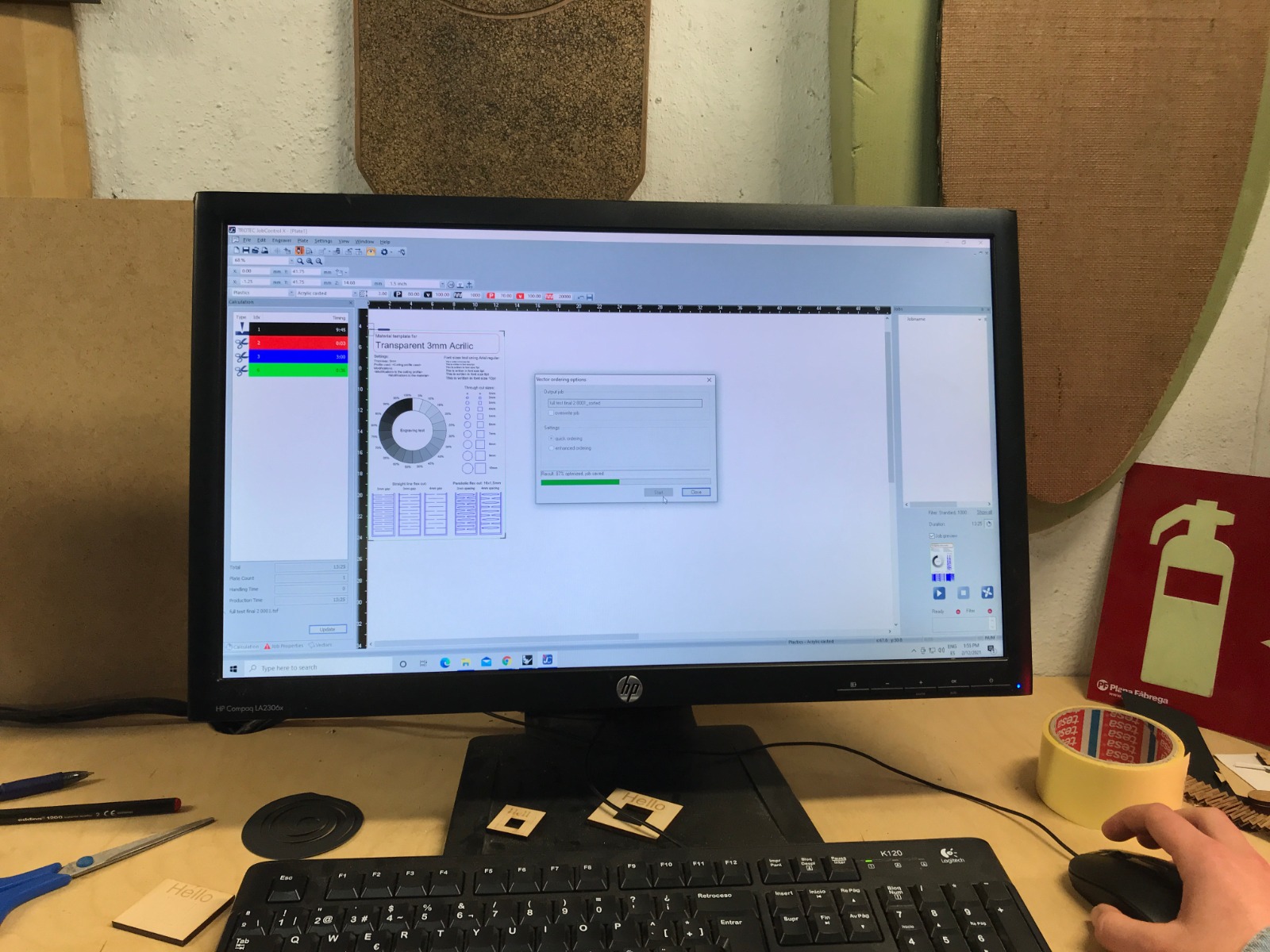
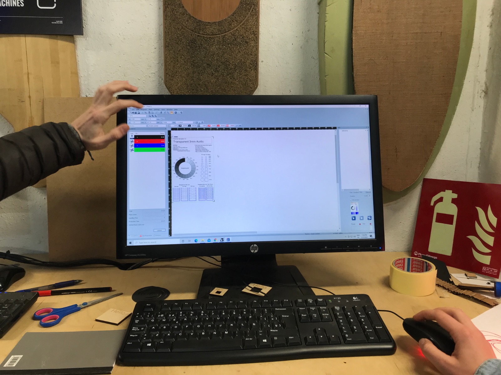
- Step 2: settings
-
Once the file is uploaded, we go to the cutting room and download the files in the machine computer. Once you have it there, simply open it on Rhino and CTRL+P to open it in the machines software. (If you haven't done it yet, characterize with colours the layers of your 2D design.). Then in JC, characterize the parameters: speed, power, type of cut (cut, engrave or raster) and HZ or ppi depending on the type of cut.
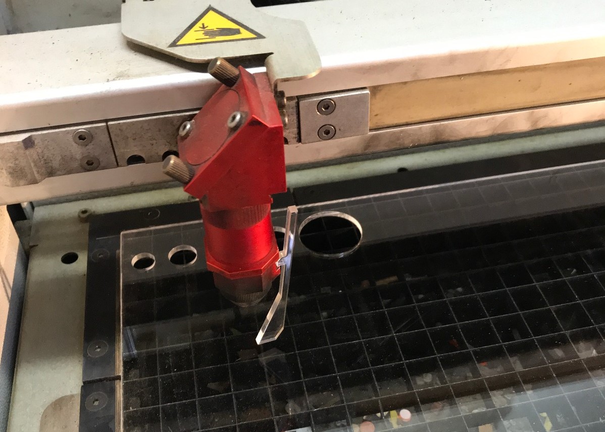
- Step 3: loading and settings
-
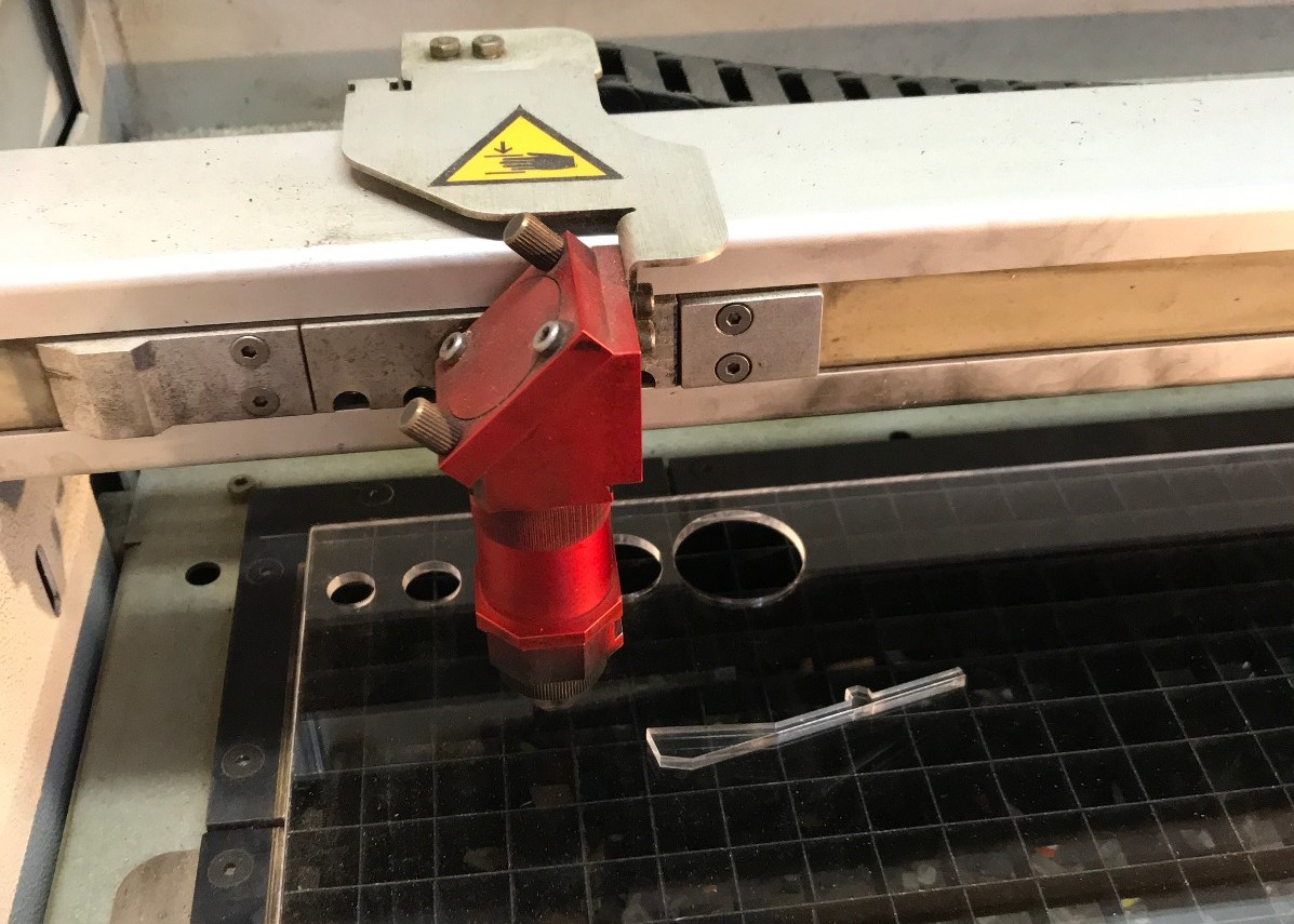
At this point, we are done with the computer so we have to take care of the materials and machine itself. The first thing we are gonna do is put the material sheet in place and focus the machine. To focus it, simly hang the template on the laser head and raise the base carefully until it falls. Check the following images to get a better idea of what I was telling you.
- Step 4: golden rules
-
If you already reached step 3, you have to remember the three golden rules before starting the machine:
- Is the laser beam focused?
- Is the air extraction on?
- Have you properly set the layer's speed and power?
If you answered YES , you are now ready to go!
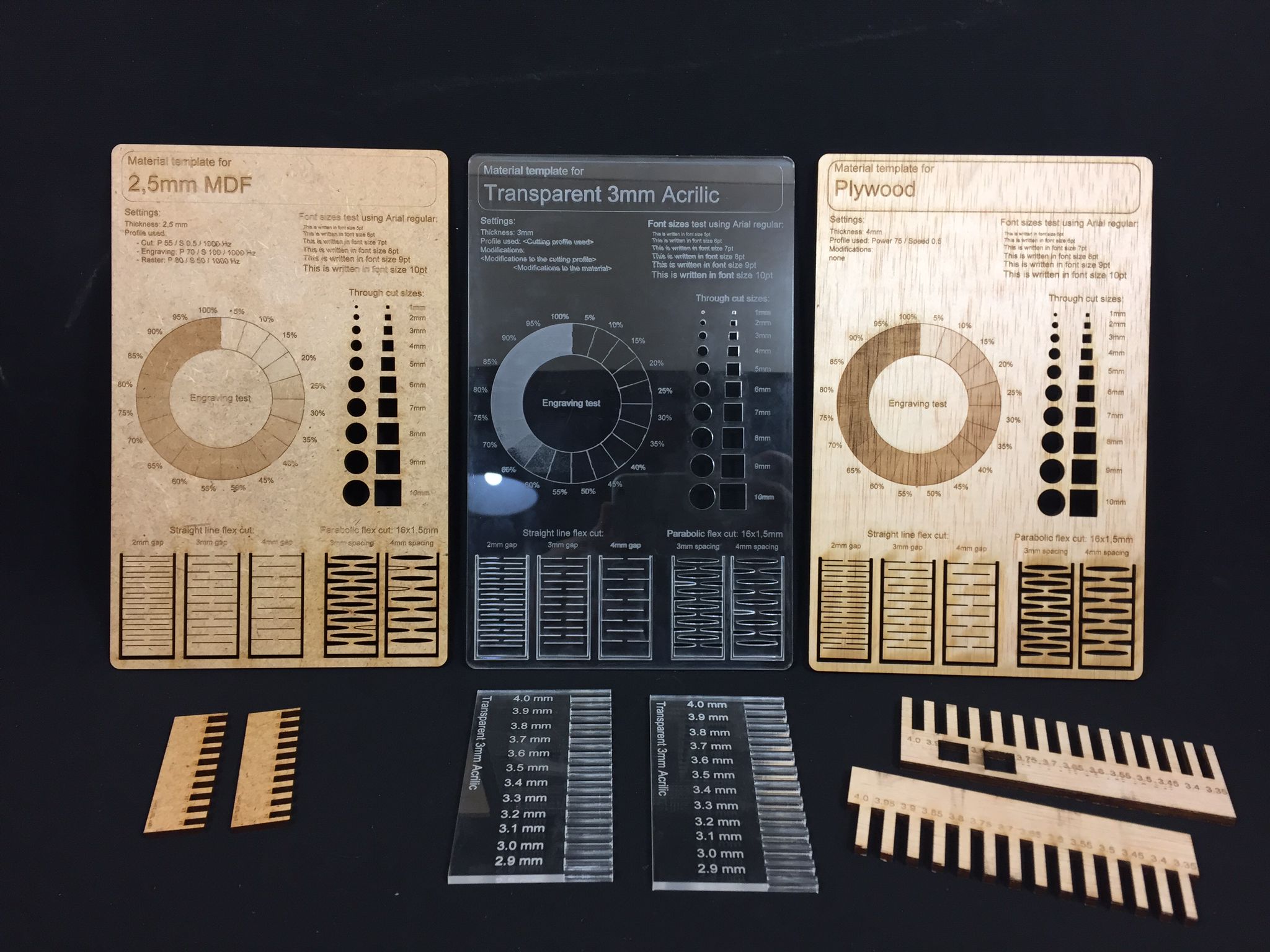
In case you can't read the settings in the datasheets, here is a small summary of the major parameters for each material.
Material settings: Power (P), Speed (S), Resolution (R)
MDF (2.5 mm)
- Cut: P 55 / S 0.5 / R 1000Hz
- Engrave: P 70 / S 100 / R 1000Hz
- Raster: P 80 / S 50 / R 1000 PPI
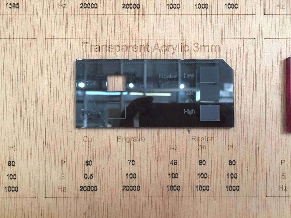
Transparent Acrilic (3 mm)
- Cut: P 60 / S 0.5 / R 20000Hz
- Engrave: P 70 / S 100 / R 20000Hz
- Raster: P 60 / S 100 / R 1000PPI
Plywood (4mm)
- Cut: P 75 / S 0.5 / R 1000Hz
- Engrave: P 65 / S 100 / R 1000Hz
- Raster: P 60 / S 100 / R 1000PPI
Vynil Cutter
As soon as it is my first experience with vynil cutters I would like to keep it simple but understand the main basics of this machines. I believe it is better to keep it simpple, but get used to this machines. If I am not wrong we will be using them for the PCB fabrication so I will eventually end uphaving to use them.
But keeping it simple does not mean making it boring. I am a huge lover of stickers and I stickbomb my laptops since forever. I would like to make a simple design of my studio branding and stick it in my laptop and phonecase.
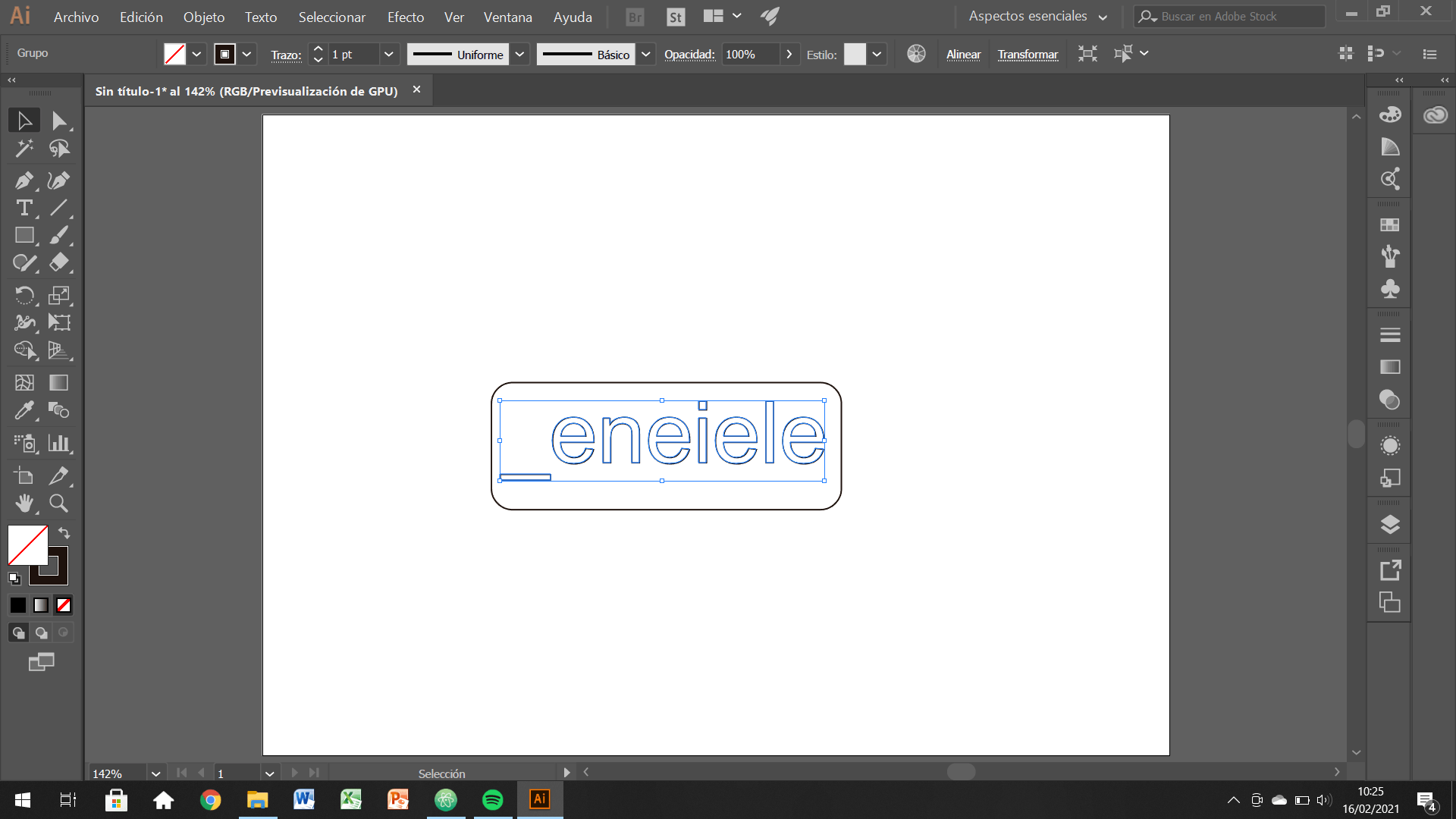
2D development
I already have the vector files ready, but I forgot the harddisk at home. So I am gonna vectorice my name with Illustrator, and send it to the cloud.
Cutting the designs
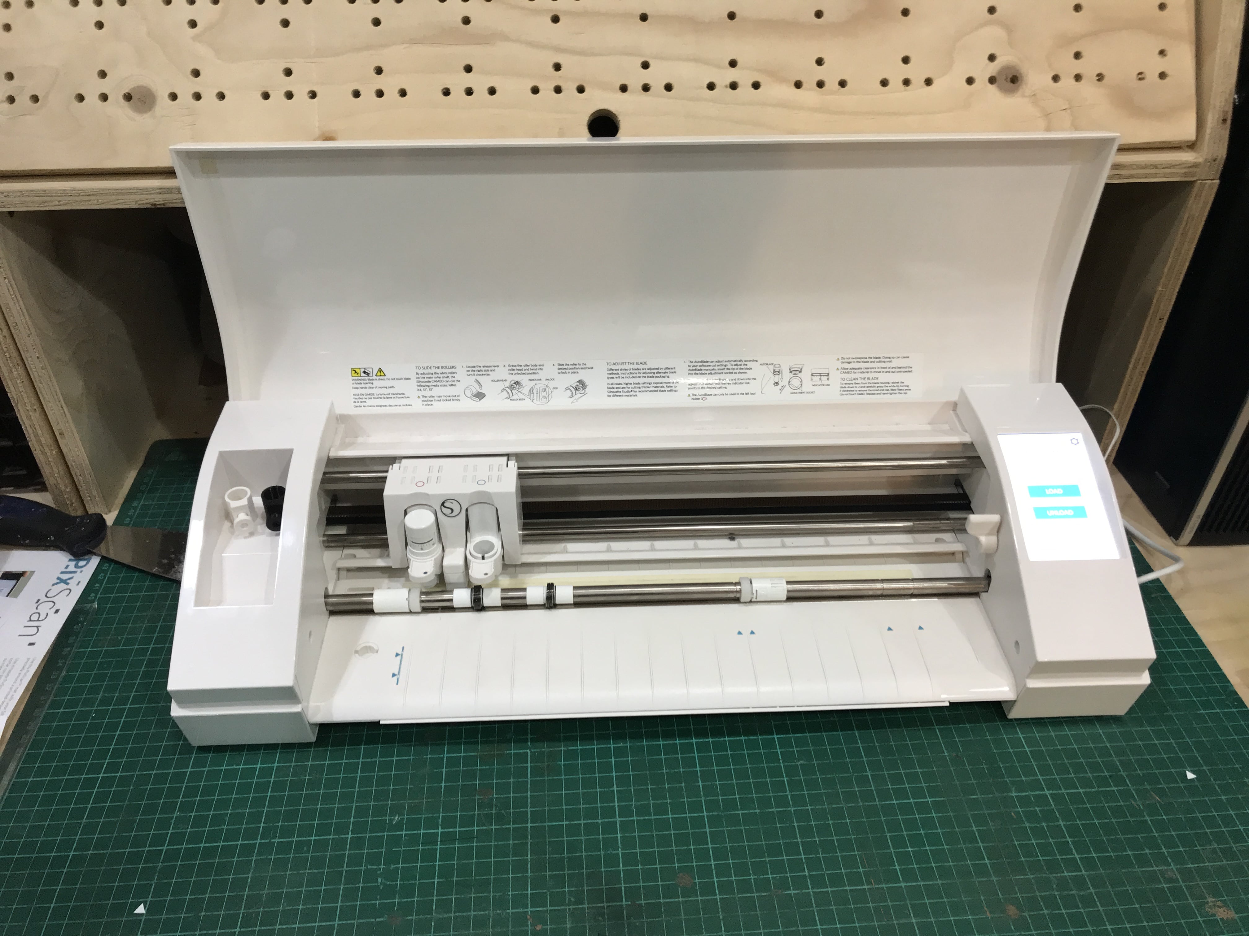
In the Lab we have two vinyl cutting machines. An older Roland CAMM-1Servo and a more modern one called Silouette Cameo .
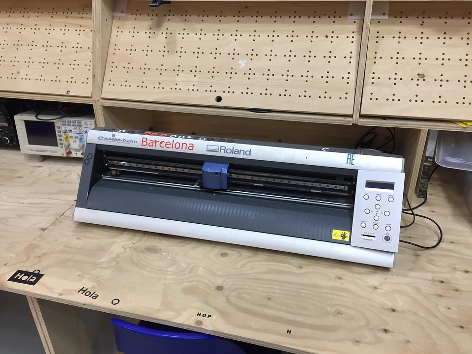
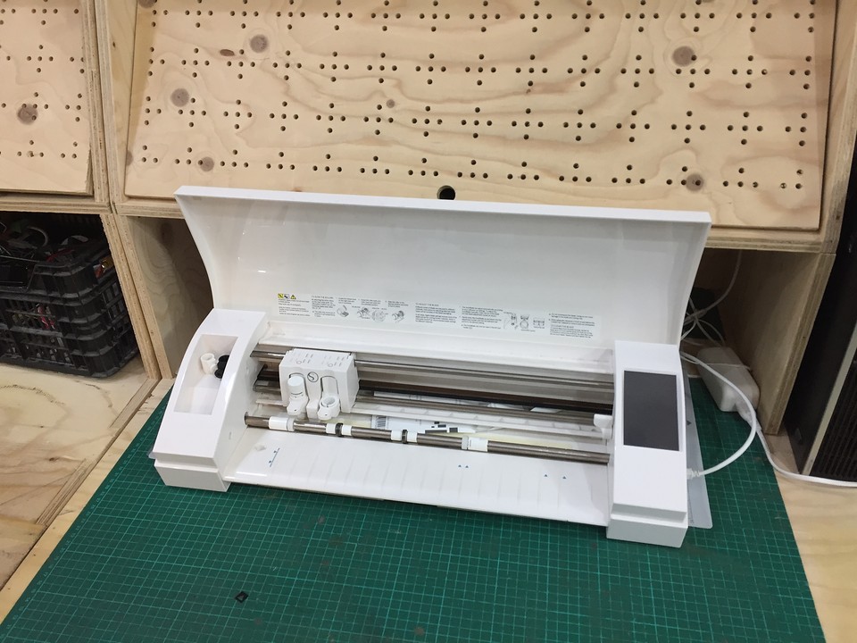
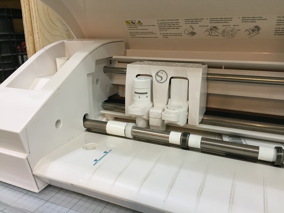
I have decided on the Cameo because it is more modern, I understand the software that controls it better and also and above all, it has an automatic system for calibrating the origin. When you have already loaded the roll in position and launch the file, the body that you see in the image below, sets the height and cutting origin automatically. I find them a great point in favor of this one.
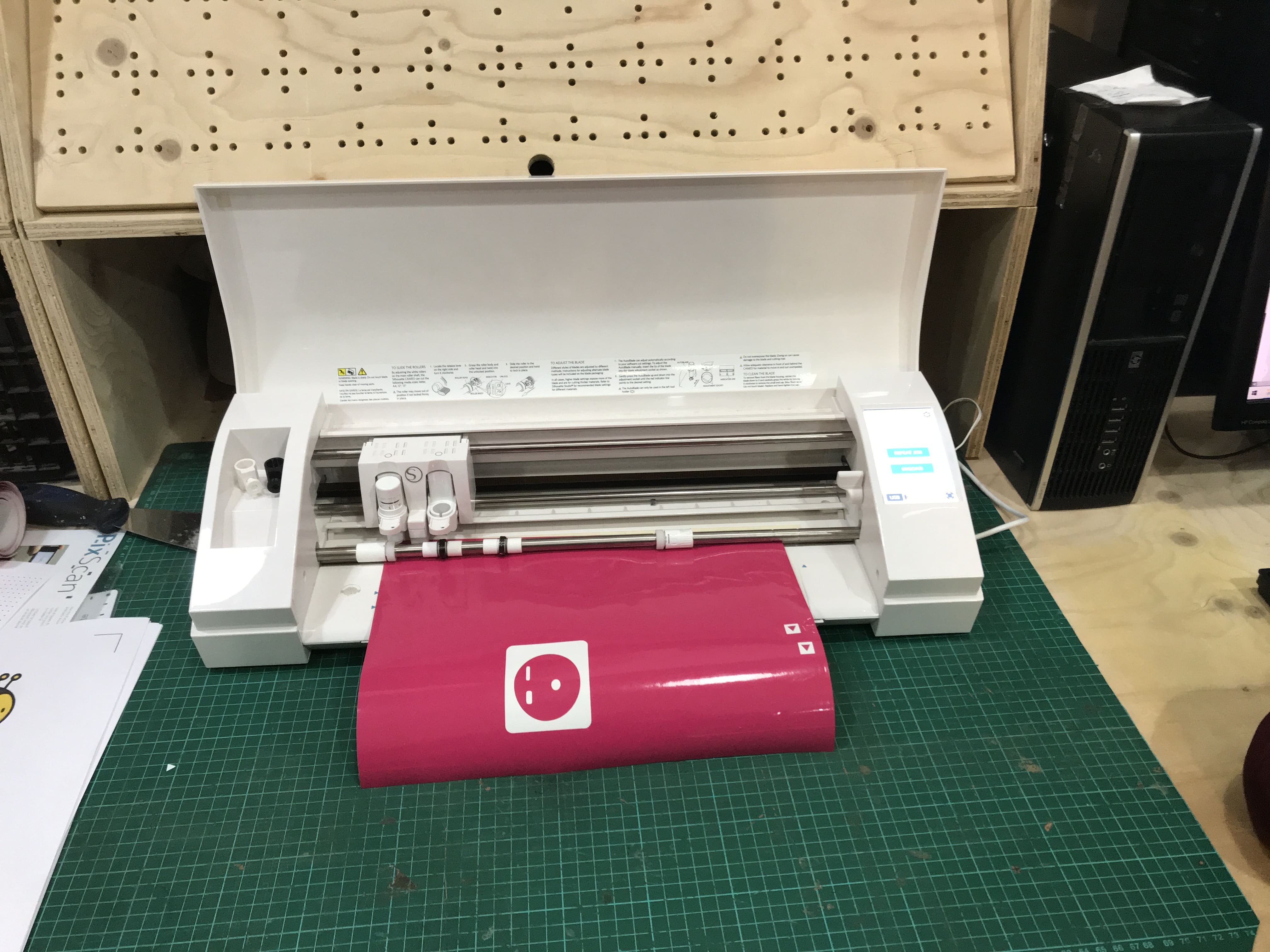
Once the designs are ready and uploaded to the cloud, I just downloaded them from the computer driving the machine. There I prepared the file and loaded the machine. Once all the settings were ready, I cutted the vynil
Final results
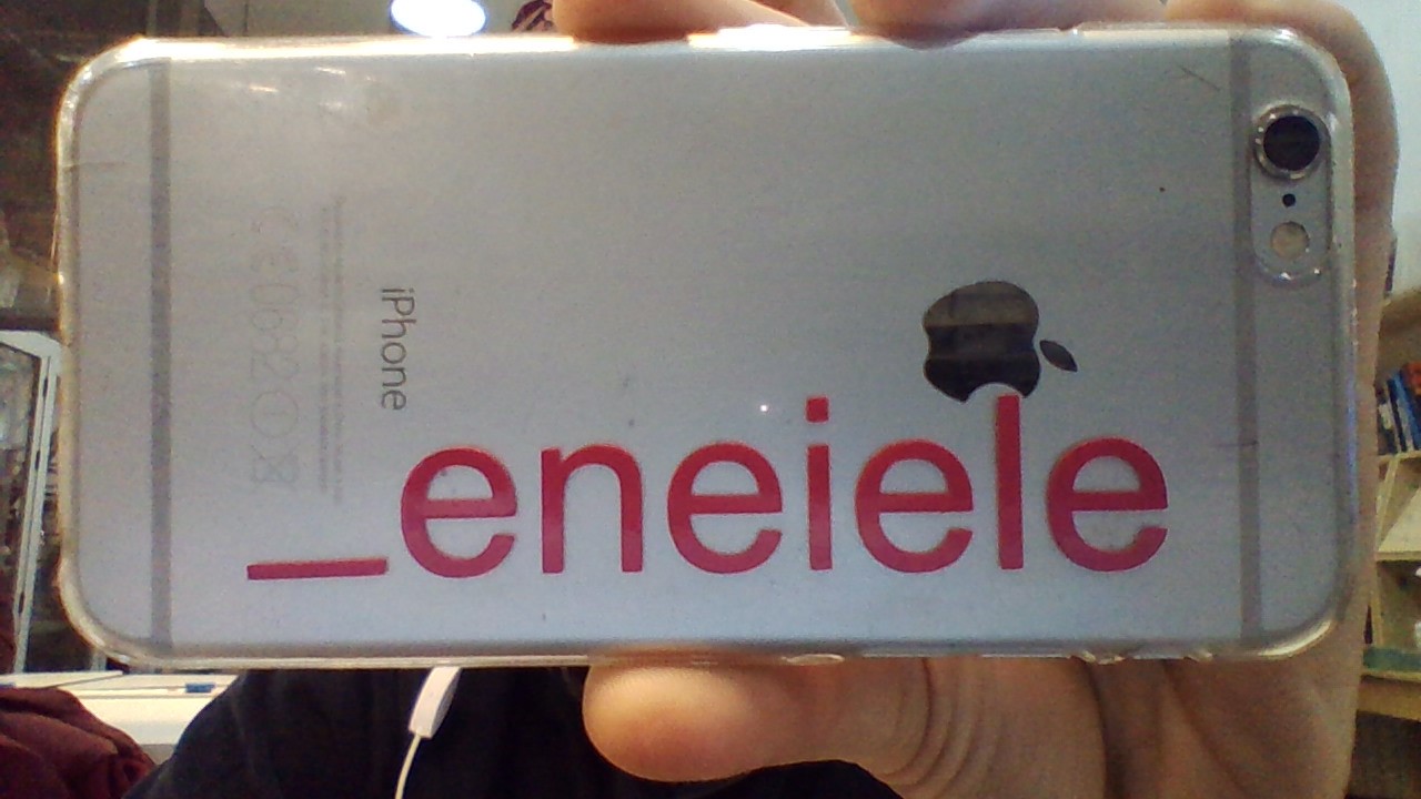
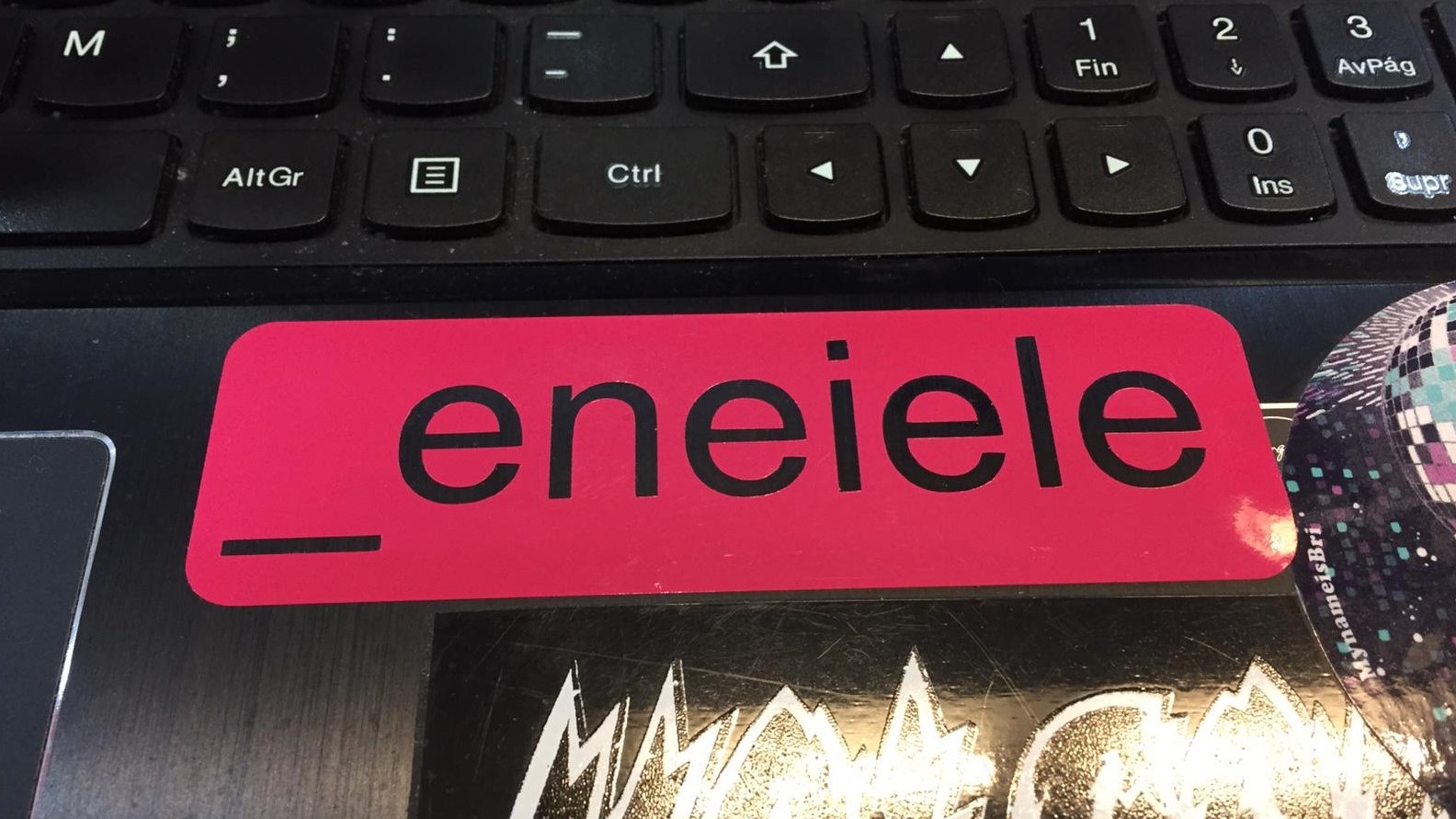
I realized that both positive and negative could be a cool sticker. I used the outter part on my laptop, because the black background worked good, and the inner part for my phonecase.
Conclusions
The conclusions of the vynilcutters are as follows:
- They are very cool machines but they are somewhat specific in the functions they provide. Beyond cutting vinyl they are not very useful.
- I find that they are most interesting in plotter form. We have been told that there are some that print as well as cut. I think those are really the ones that would be interesting for a design engineer profile like mine. You could print anything, cut it on the spot and use it without using many machines.
- I have been looking at prices of vinyl cutters and I have been amazed: they are very expensive !!!!! The Roland we have in the Lab, but with an elevator foot and the possibility of printing as well as cutting; It costs almost € 6,000. Wow!
Parametric 2D modelling
Parametric sketching means, working with easy changing values that work together. With this you can scale, change and modify your designs in a easier way than changing all geometries by hand. In my case, I prefered to work with Fusion 360, because I feel more comfortable with.
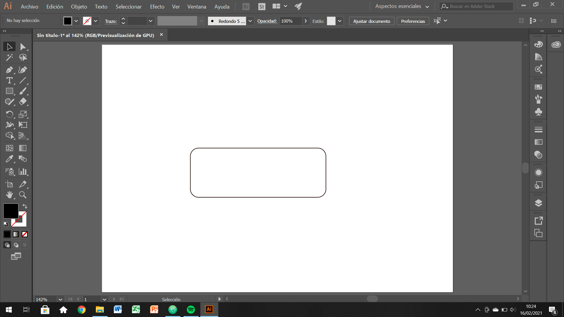
What I did was sketching the major shape of my pieces for the construction kit and the add sketch dimensions. But instead of adding numerical data, you relate that number with parameters. For example, a data that you might change several times is gonna be the width-kerf.
If you check the images below, you can see how I did my design. I put special atention in the widths, depths and kerf dimensions.
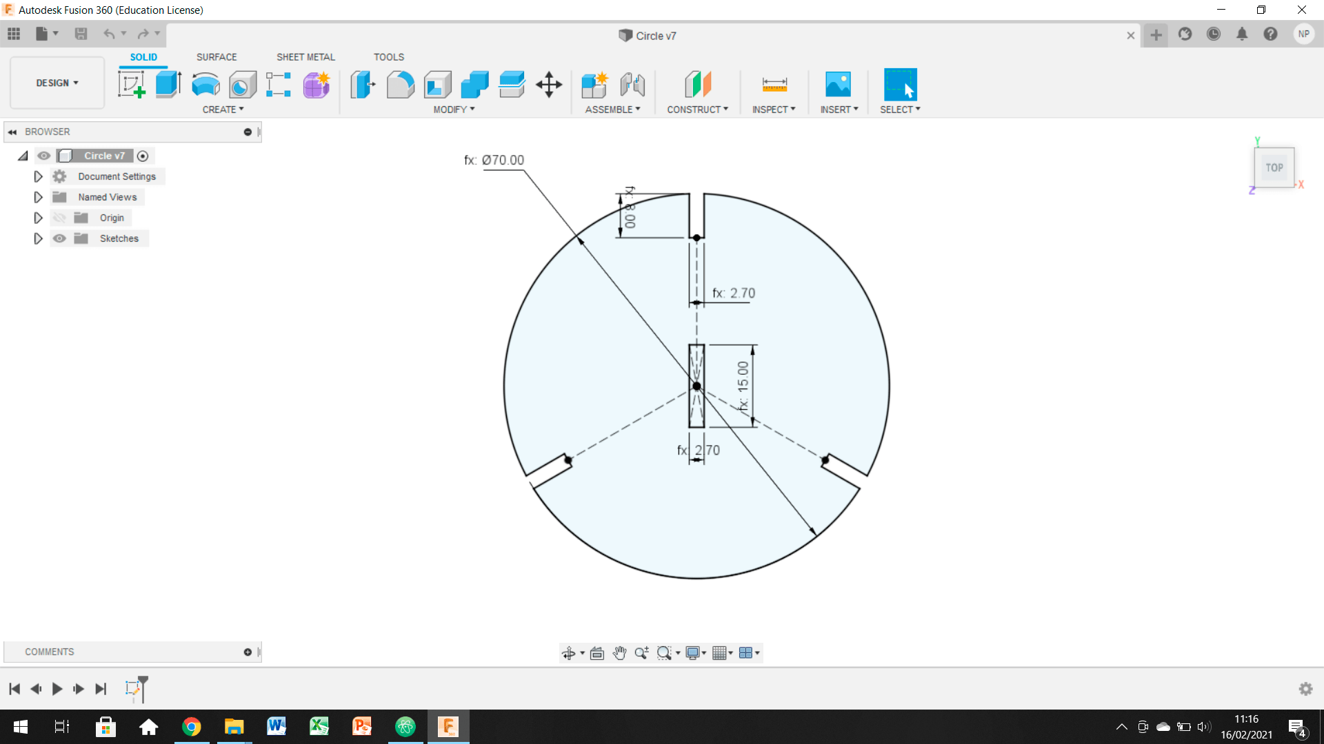
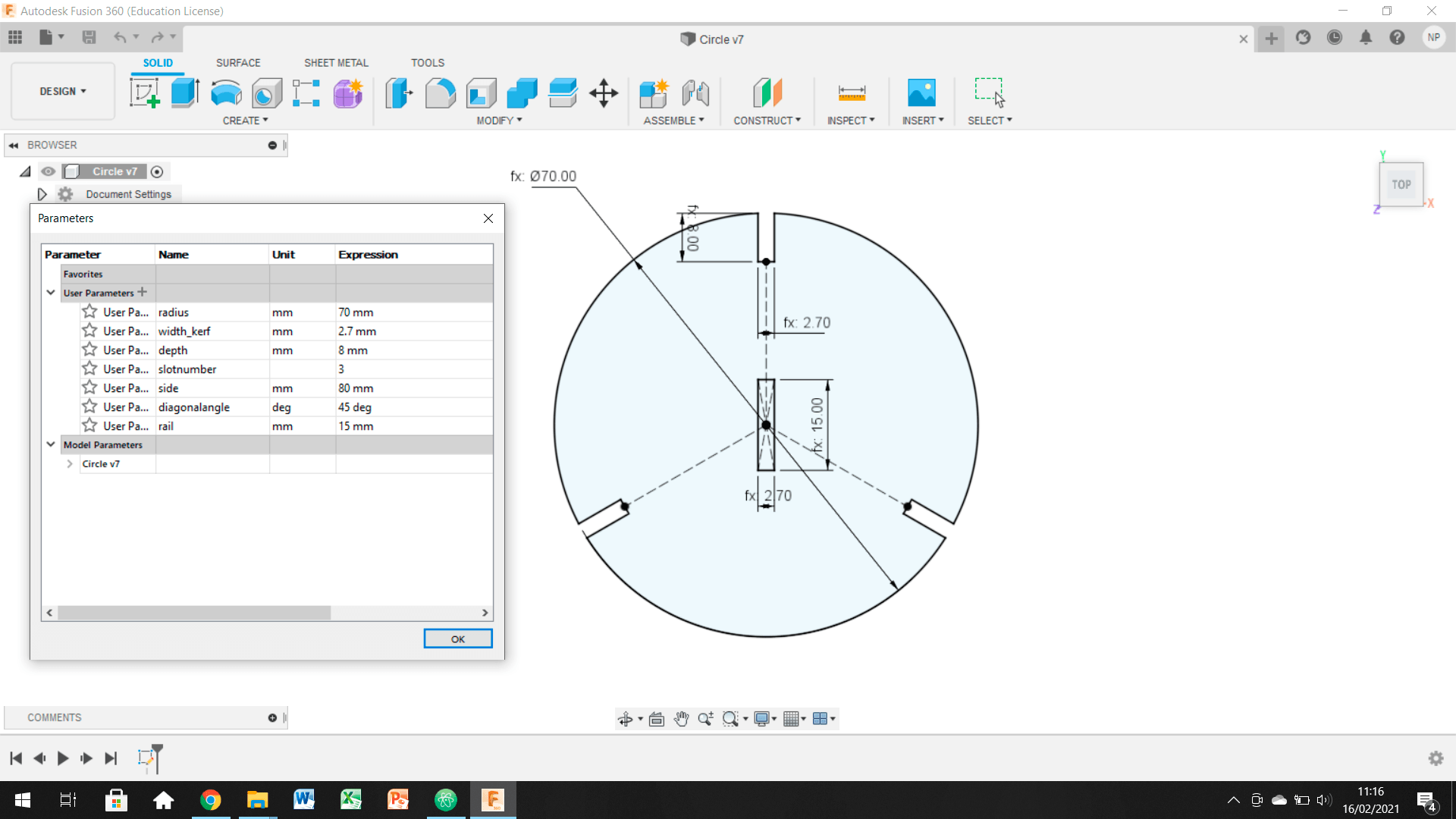
Adding this parameters and the geometrical sketch constrains, fully blocks the design and you can be completely sure that the sketch is correct. Then the next steps are:
- Save your sketches as DXF and import them to rhino.
- Nest the pieces in your workspace.
- Group the contours in layers, following the color pallet that your laser cutter software uses.
- Erase or optimaze duplicate lines to prevent double cutting.
- Optimize the laser beam route to save energy and machine's lifecycle.
- Upload your file to the laser cutter software and set the cutting parameters.
Laser Cutter
I have some previous experience in laser cutting, because of my precious degree studies. But I never had the chance to explore the limits of the technology. That's why I jumped straight into acrilics, because I already used wood and cardboards. First thing I realized was that kerf is way more demanding with this materials.
My idea for this assignment is to understand the acrilic's behaviour when laser cutted. As soon as my final project may involve this material, I believe it is a good idea to start exploring it. I would like to do a mobile but from a parametrical approach. I am going to develope an equilibrium game for kids (or not so young...) fully built with acrilics.
Iteration 1
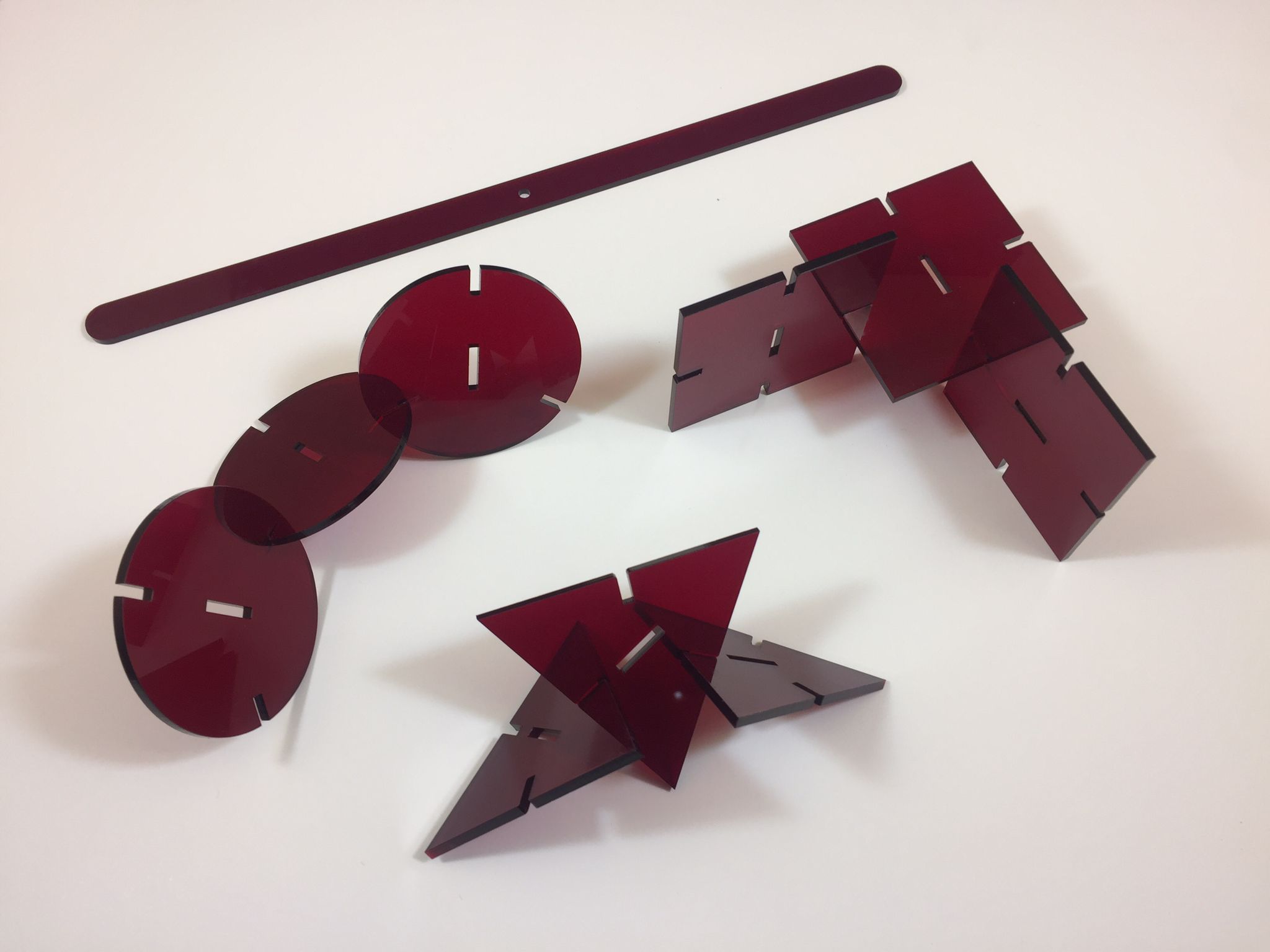
Apart from the week assignment trials and errors, I first cutted the basic shapes I want to use fot the mobile. I am going to focus the aesthetics in the bauhaus rational geometries and colors. Therefore believe equilater triangles, squares and circles are a good choice.
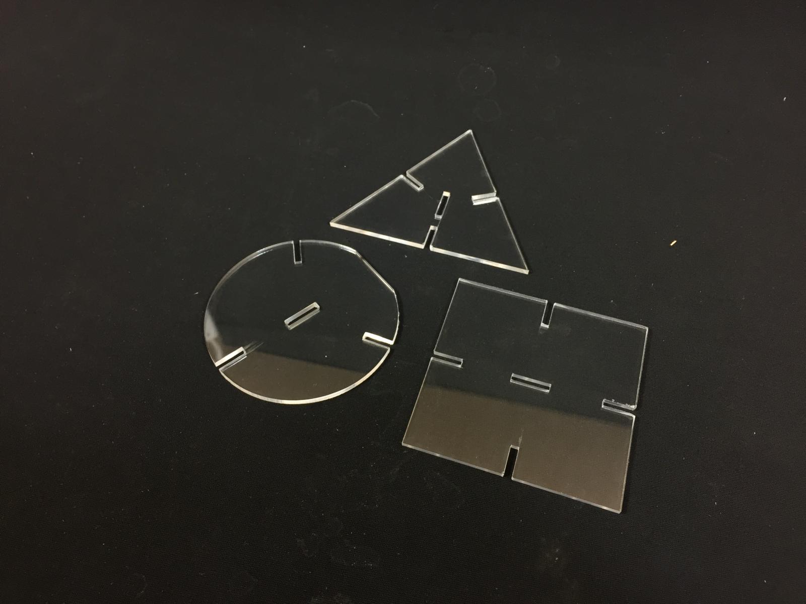
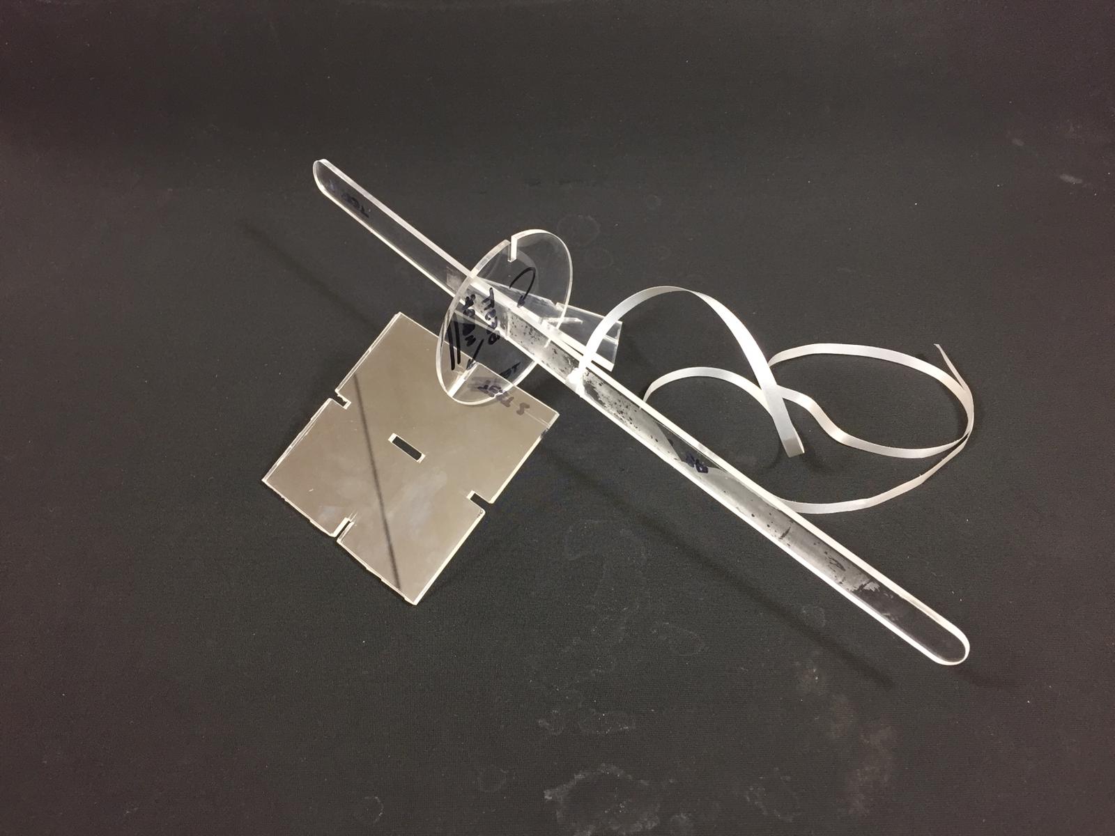
To not destroy some colored, and expensive, acrilics I did some trials with transparent acrilic. As you can see from the precious images, I made several mistakes:
- Kerf was too tight and the slots did not slide properly. I used a 2.8 mm width, but ended up realising that the laser cutter cutted instead of 0.1mm on each side, it cutted 0,125mm. So the next obvius step is to try a wider kerf of 3-0.125*2 = 2.75 kerf.
- The placement of my design in the material was incorrect and the circle ended up having a flat spot. The laser went outside the acrilic sheet so the shape is not correct.
- The shapes are way to big and will bend the rails of the mobile. Also I have to develope the rail and the mechanical system to hang it from the ceiling.
The laser cutter settings for this cut were the default ones from the Laser Cut Chart we have at FabLabBarcelona:
- Cut: P 60 / S 0.5 / R 20000Hz
Iteration 2
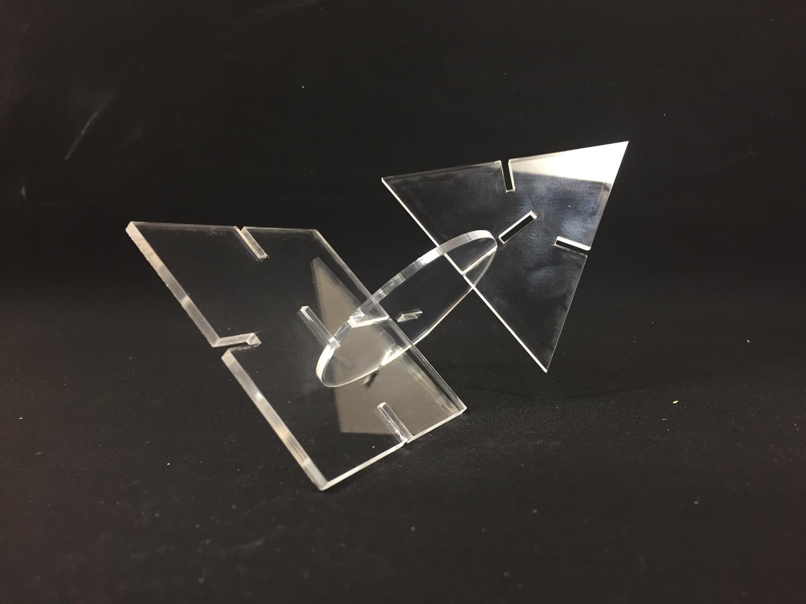
In this second iteration I tried also to explore the behaviour of the pieces when sliding through the rail. That part went well, but not with the kerf. I believe the acrilic sheet bended during the weekend because most of the kerf fitted properly in one direction, but not in the other one. I checked the kerf in my parametric files and seemed to be ok.

I thought this was going to be the last iteration, but I was wrong. Kerfs were not correct at the end and the machine was not working well. After some research I eventually realized some more mistakes:
- The guys at Fab Barcelona had been working in the laser cutter, trying to replace the current lens. Due to their changes, the machine was not working at its finest and ended up ruining my cuts. The thing was that the lens was dirty and was not developing its maximum power. This resulted in the cuts not going through the material and therefore not being able to trim the pieces cleanly.
- I tried to sand the edges to be able, to at least try some pressfits and kerf. HUGE MISTAKE! By sanding the edges all the geometries twisted and ruined the test. At least, I was able to undestand the perfect fit: 2,70mmif working with 3mm thick acrilic. Basically you have to keep in mind that the laser beam width through the material is 0,15mm on each side.
The laser cutter settings for this cut were exactly the same thant he ones for first iteration. But as I told you, due to some works on the machine it was not cutting all the way through:
- Cut: P 60 / S 0.5 / R 20000Hz
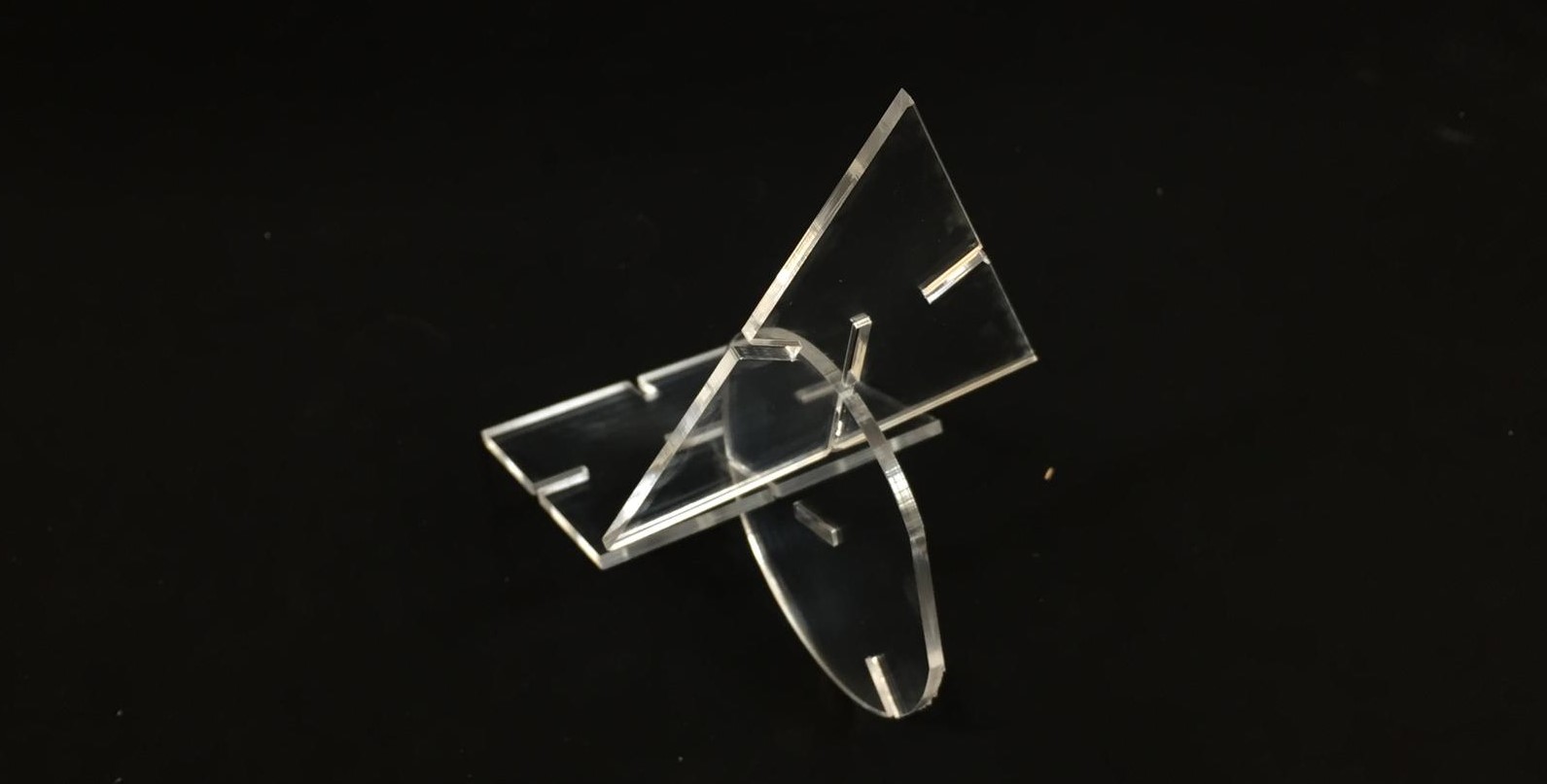
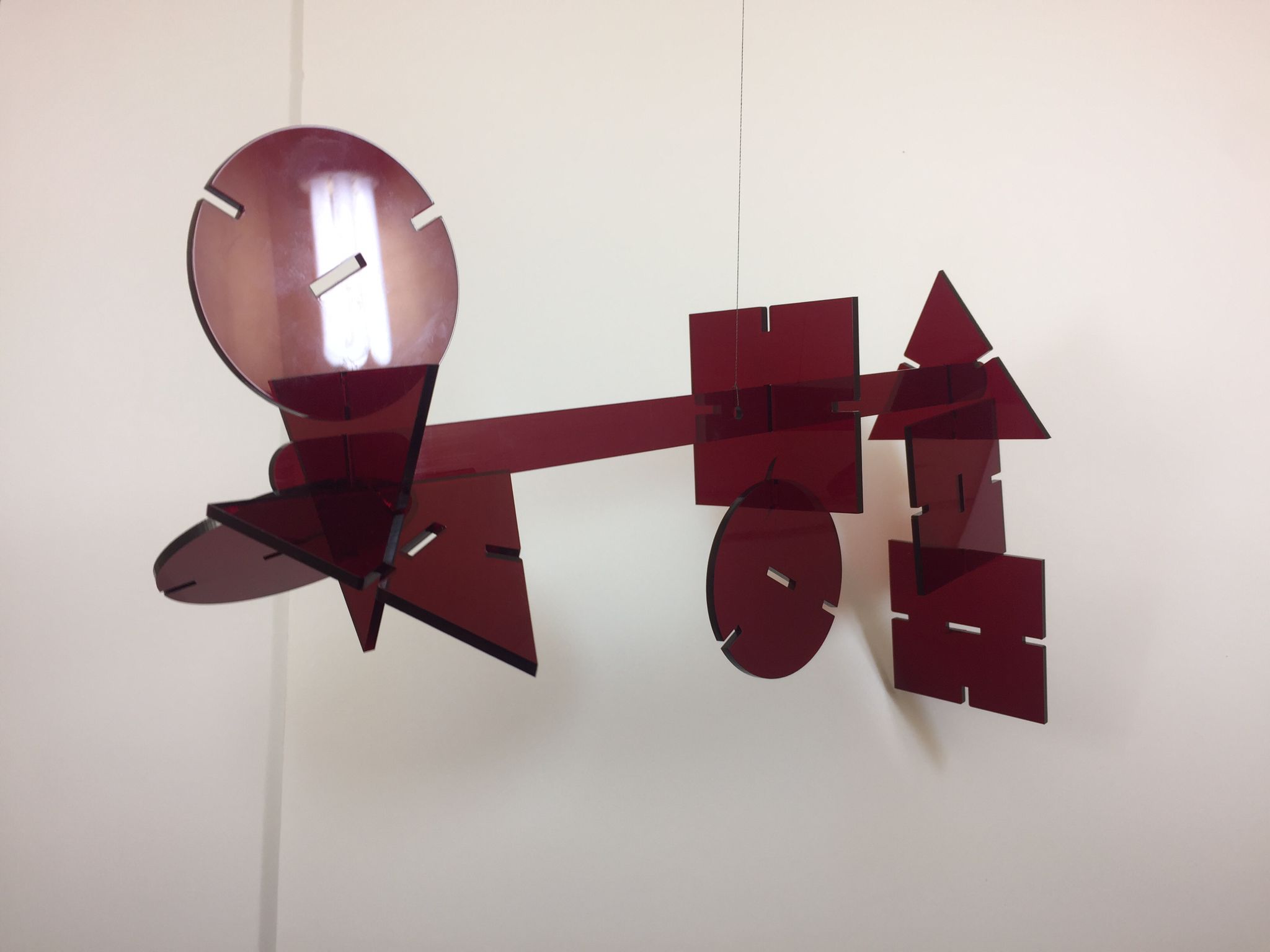
Iteration 3: final results
This third iteration was finally definitive. I switched to a blood colored acrilic for a more cool look. The width was the same as the transparent (3 mm) so there was no problem with the kerf. All went ok and was finally able to see the mobile fully working.
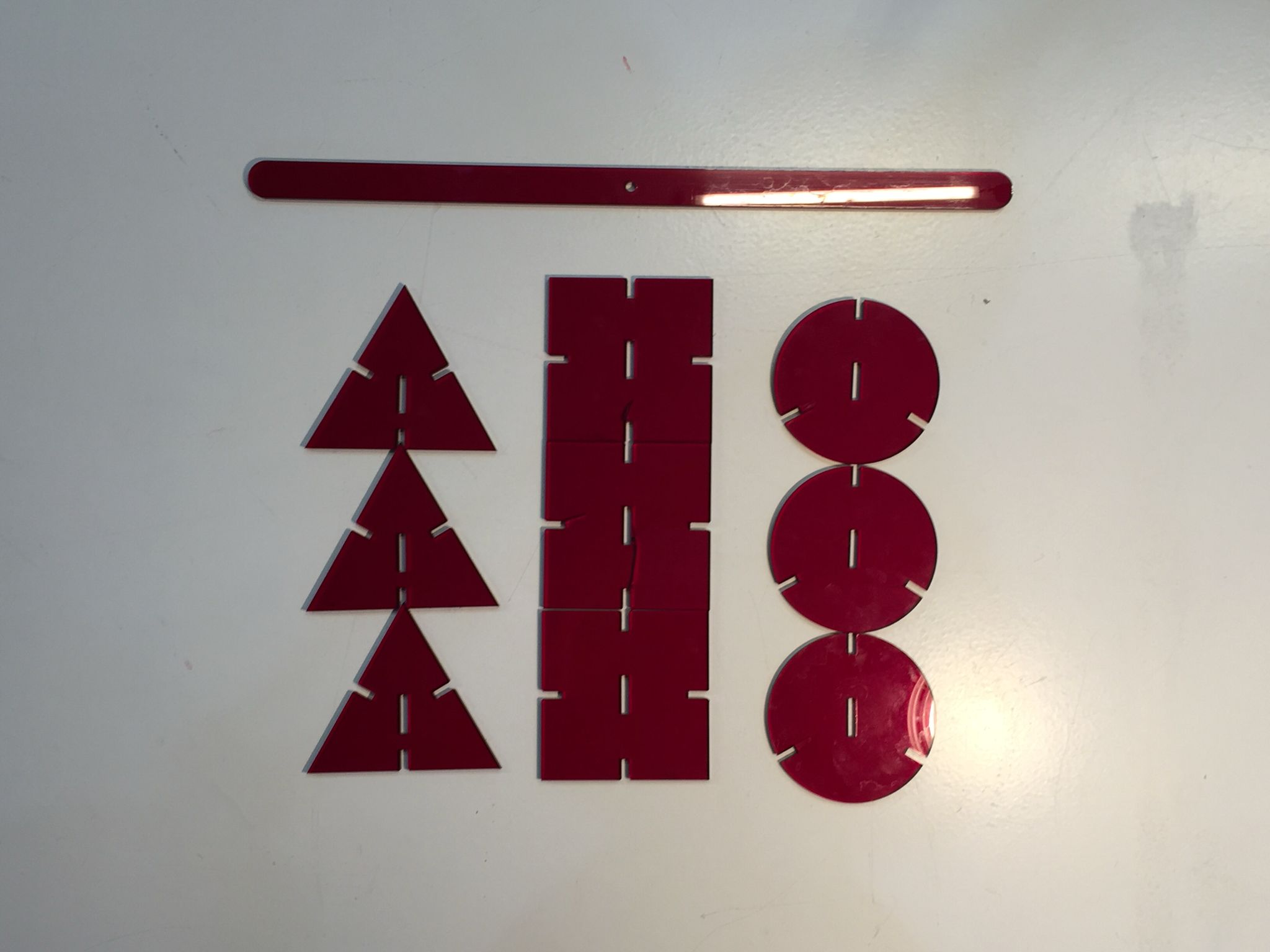
The idea apart from the parametrical design is to slide the constructions as you wish and create an equilibrium design. Or if not simply keep it crooked.
If I had more time to develope the idea and final design, I would have liked to explore more the color palette and maybe the adition of some more rails to create an even more complex structure.
I believe it has been a cool idea to create a mobile and start exploring its behaviour looking forward to my final project.
Final Parameters
For this last attempt I have tried to play with the parameters to get the cut to be as accurate as possible. Reviewing the previous cut (iteration2) I see that the edges are clean and do not present bumps. That means that the power is almost fine and that the hertz at which the machine works are fine. I have considered that raising the power a little and lowering the speed the cut would be correct.
Finally the ones I have used have been the following:
- Cut: P 70 / S 0.4 / R 20000Hz
- Kerf: overall 0.15mm per side. Final with for my join 2.7mm for a 3mm acrilic
Indeed the settings have been correct and the pieces of the game have been great! I am happy with the result but some thoughts have been running through my head during the week.
Conclusions and Thoughts
I find this technique to be a great tool for project prototyping and even in the hands of an expert, industrial results can be achieved. In the past I had worked with industrial laser cutters to cut sheet metal, but always from a design point of view, I had never used these machines so much on my own. I remember that when I was designing the parts, the colleagues who operated the laser cutter told me to respect certain geometric tolerances that I understood all at once this week.
In a way, that the laser modifies the measurements that you have thought for your designs is frustrating because depending on the machine you use or how it is set, you may have problems with the adjustments. This week has been the perfect example, when someone modified the settings of the machine the cuts resulted in a failure. I see that this laser cutting thing is pretty focused on trial and error. It is always better to do a few small tests instead of trusting that the cutter is well set. It is also a good way not to waste expensive materials, and make mistakes.
How to use the Laser Cutter 101
I think that doing a small tutorial for the future can be interesting to remember those relevant aspects of the workflow.
- Step 1:preparation. Draw your files and export them for rhino 5, as it is the software the laser cutters use in our Lab.
- Step 2:Layers and color. The machine's software uses colors in order to undestand what are the shapes to cut. See what order the colors are in and paint your layers with those same colors (the default works better)
- Step 3:Material Put the material in the desired position and grab it with a little paper tape at the edges. That will prevent it from moving while being cut.
- Step 4:Machine setting Place the laser where you want to start cutting. Place the stick to gauge the distance and slowly go up the table until the stick falls. Turn on the extraction of gases on the machine and on the general switch on the wall.
- Step 5:Open the machine software. Import the files in Rhino 5 and click Print. Put the ketch in place by using the laser beam pointer in the software.
- Step 6:Cut Settings Activate the layers you want to use and add the parameters for your material.
- Step 7:CutLaunch you file when ready. It is important to stay close to the machine and be aware of possible flames or damage to the cut. Cutting by "heat" can generate a fire quickly. Stay close and watchful!
I hope that the next time I have to use the laser cutter, this tutorial will help me remember the important steps and details of the machine's workflow.
Precious Plastic (local project)
This week's local club has been super interesting, and I want spend a couple minutes explaining a bit more about this great project.
Fab Labs are big users of plastics and Precious Platics want to add their own grain of sand to the topic. Usually when laser cutting or 3d printing, a big amount of plastic is thown away because it can't be used anymore. That's why our Lab is trying to develope open source machines that bring back to life some of those plastics (basically those than can be reused or recycled by treating them with heat.)
Link to Precious Plastic website.
Original Files
Link to Original files from this week.
What to improve for next assignments?
This week has been tough, some big issues not realted to Fab Academy forced me to work in a hurry whle I was at the Lab.
What to improve during week 3?
· Try to take it easy and focus myself.
· Keep the good mindset and keep documentating my way through the week.