vinyl Cutter
The Machine: Roland GX-24.
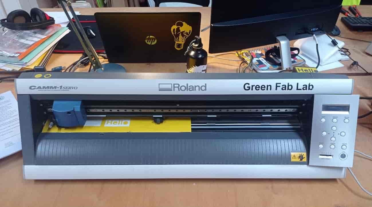
Before starting to work we need to set different paràmetres of the Machine.
- The size of the vinyl sheet. (automatically done by the Machine).
- The cutting deepness, we can manually adjust the blade screwing up and down the support.
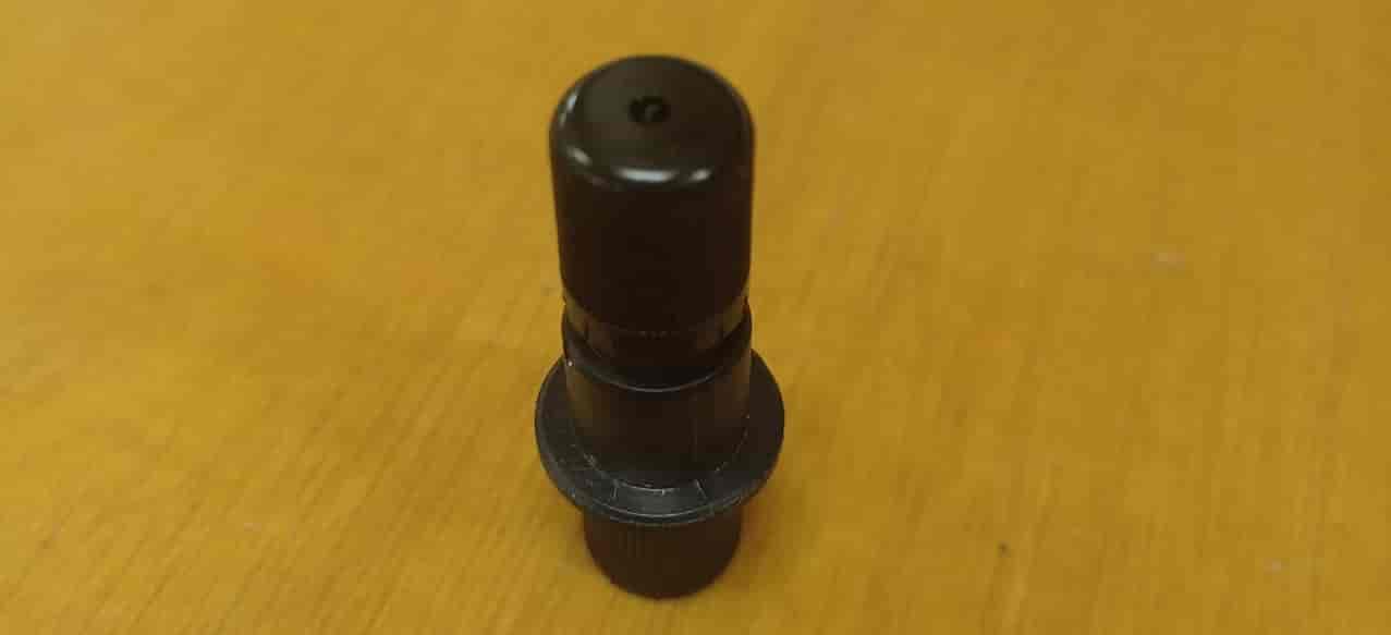
Then, to verify the cut, we can launch a preset test program.
It will make this kind of cut.
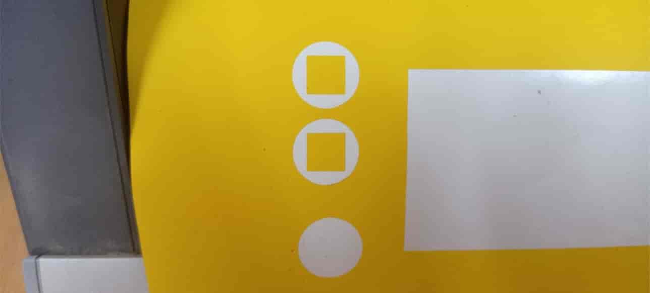
If when we remove the round cut on the vinyl the square remains stuck, and the paper below it hasn’t been cut, the cutting deepness is the proper one.
The Software: CutStudio.
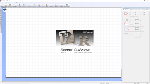
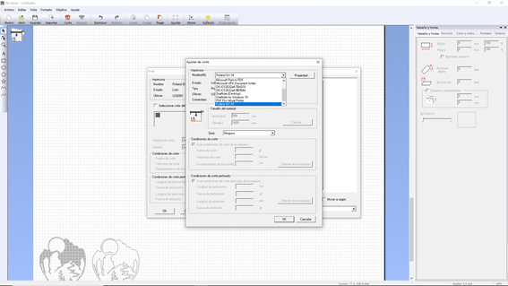
When we have the Machine ready, we have to set into the cutting properties of the Machine that we are going to use.
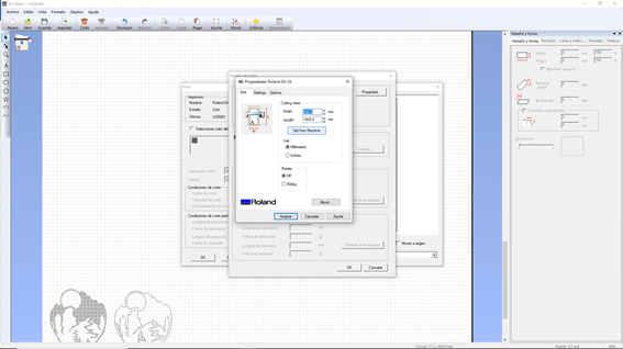
After that we need to import de sheet sice from the machine.
Then we need to adapt the image that we want to cut in PNG. And import it to the Cut Studio, to define the profile.
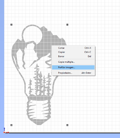
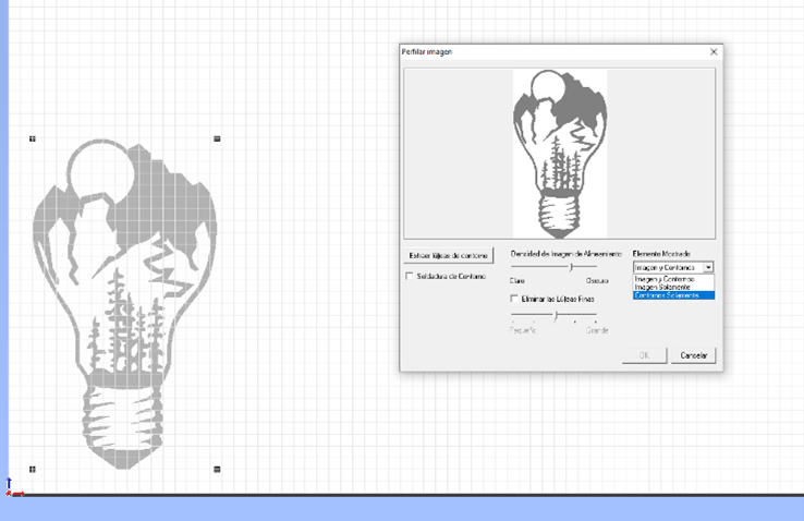
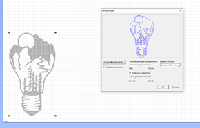
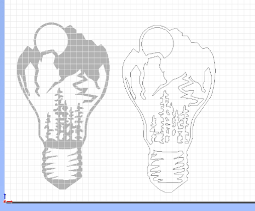
Once we have everything set, we can launch the program.
Here you can see all the process.
VID_20210211_215612 from Marc Garcia on Vimeo.
And The result.

LASER CUTTER
The Machine: PC 16/10
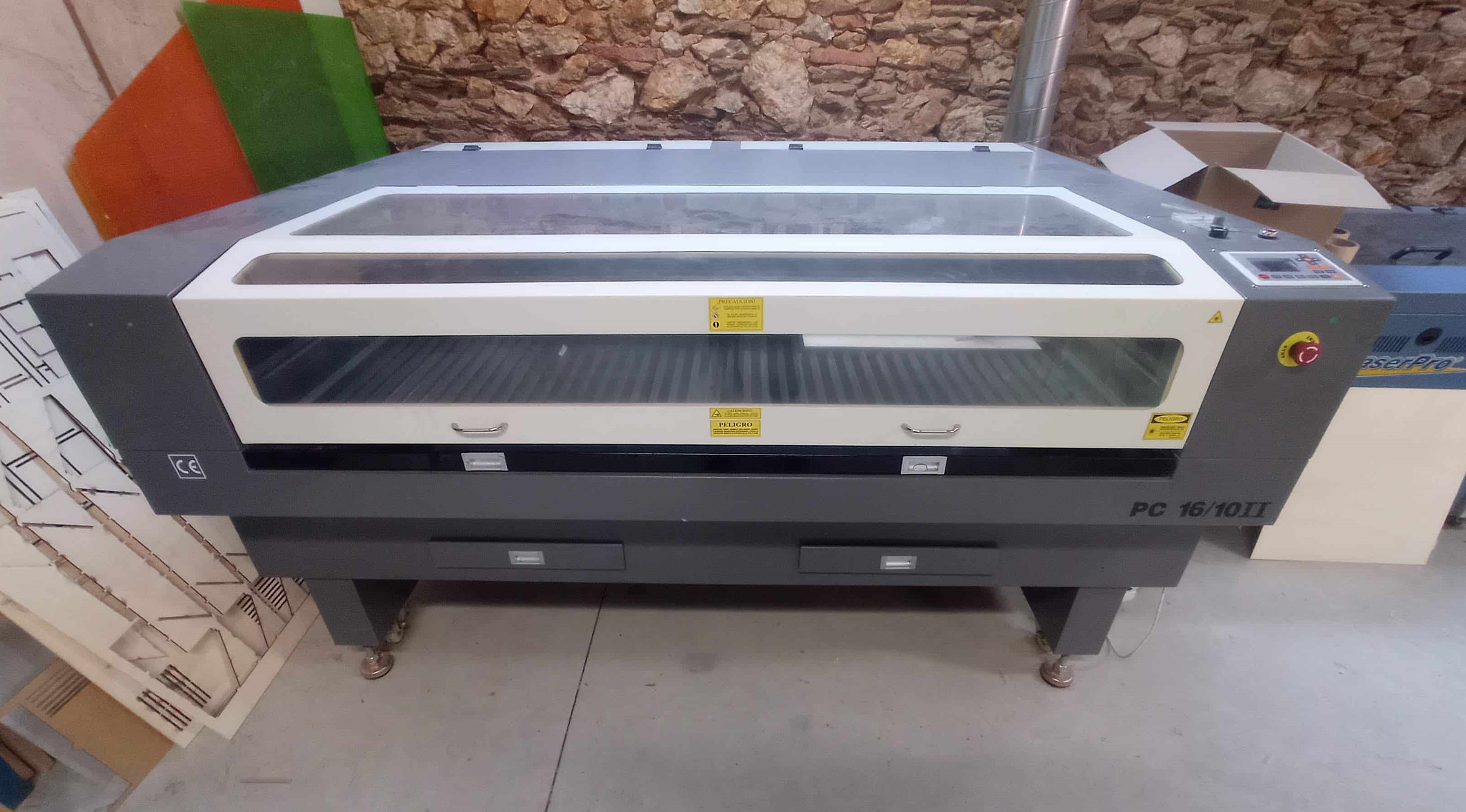
Before Staring to work, we need to set different paràmetres of the machine.
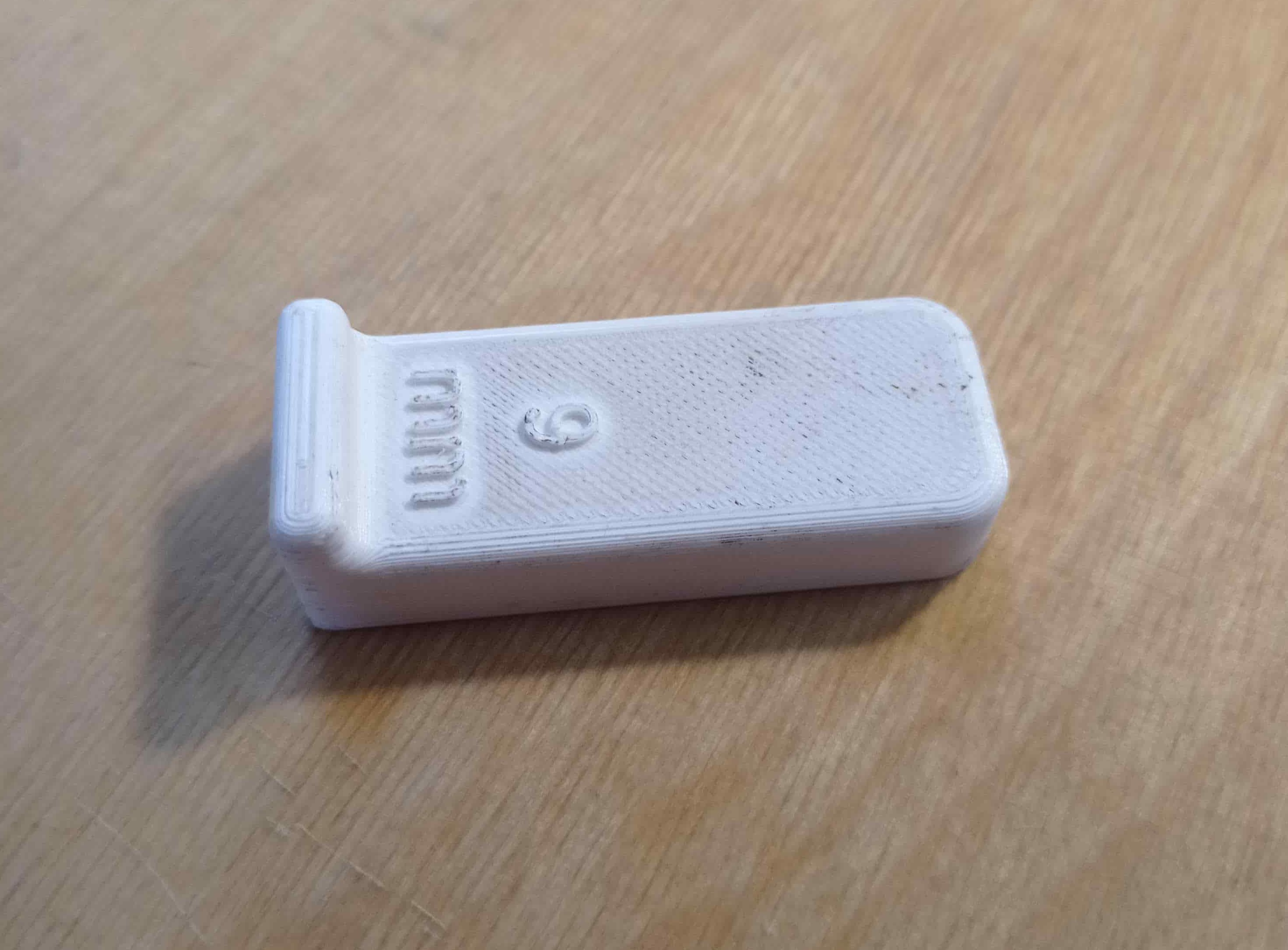
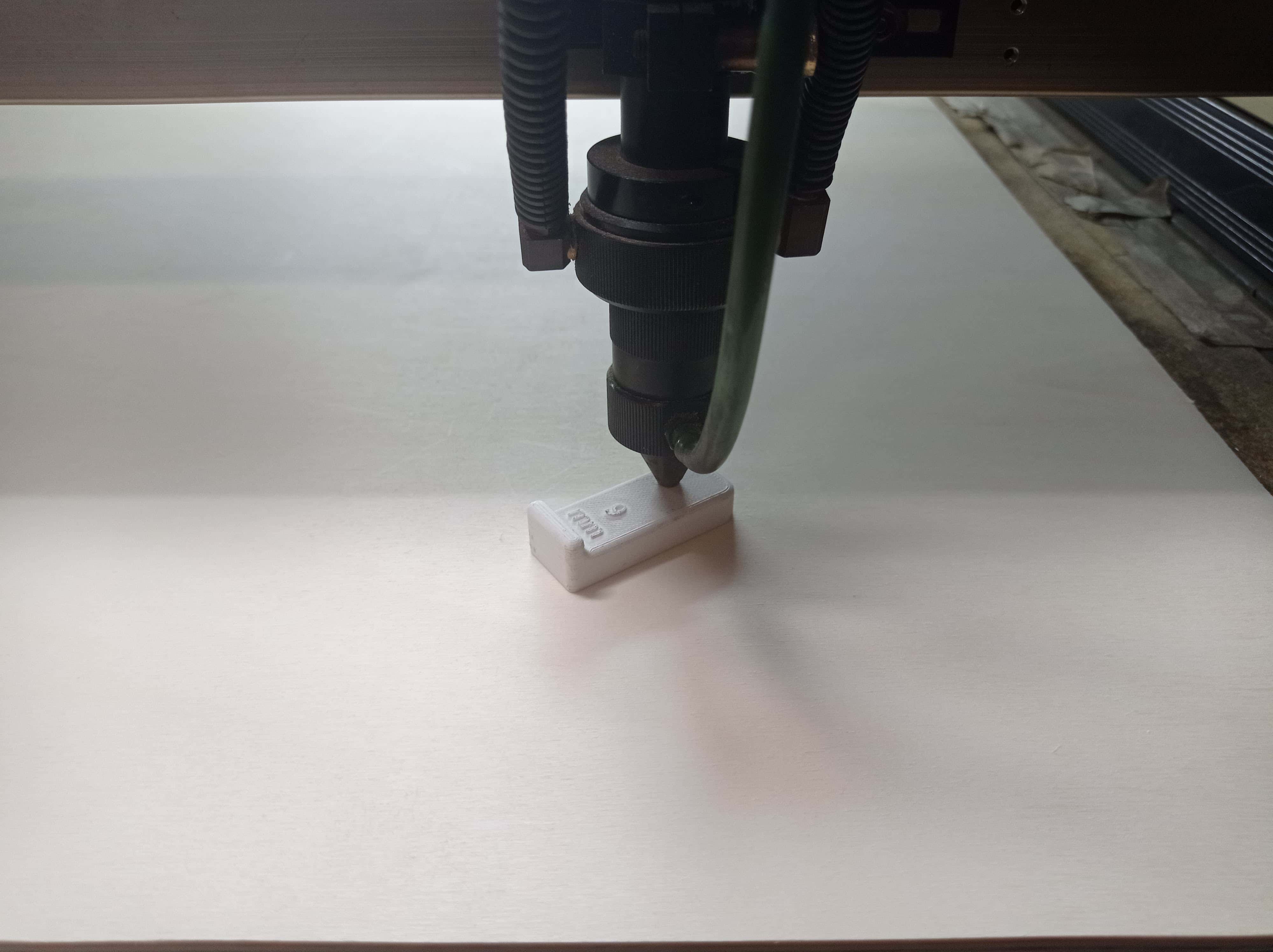
- The distance of the top of the board to the nozzle, in our machine, has to be 9mm, for that reason I've printed a 9mm piece to make the setting more accurate.
- To set the origin, we can place the nozzle over the board, using the arrow buttons of the control panel.
When we are in the right position, we can press the button origin, then our 0,0 it'll be there, the most usual place to set our zero is the top-right corner.
Then, to verify the cut, we can launch two programs to test the kerf, the power, the speed and the resolution.


- On the Left: kerf test
To know the kerf that is producing our machine on the material that we've choose (in my case 3mm MDF), we need to cut this kind of comb.
In my case I started making slots from 0.2mm more than the thicknes of the material, and reducing each time 0.1mm.
- On the right: Speed, Power and Resolution test
To know the speed that we need to cut throw the material we choose a power (70%) and then we test cutting at different speeds, from 10mm/s to 100mm/s.
To know the best power to engrave, we set, a at the same speed and resolution, different powers, from 5% to 40%.
To know the best Resolution to engrave, we set, at the same peed and power, different resolutions, from 50 DPI to 400 DPY.
Now We have the machine well seted and we know whitch parameters are the best ones to use in our work.
parametric construction kit
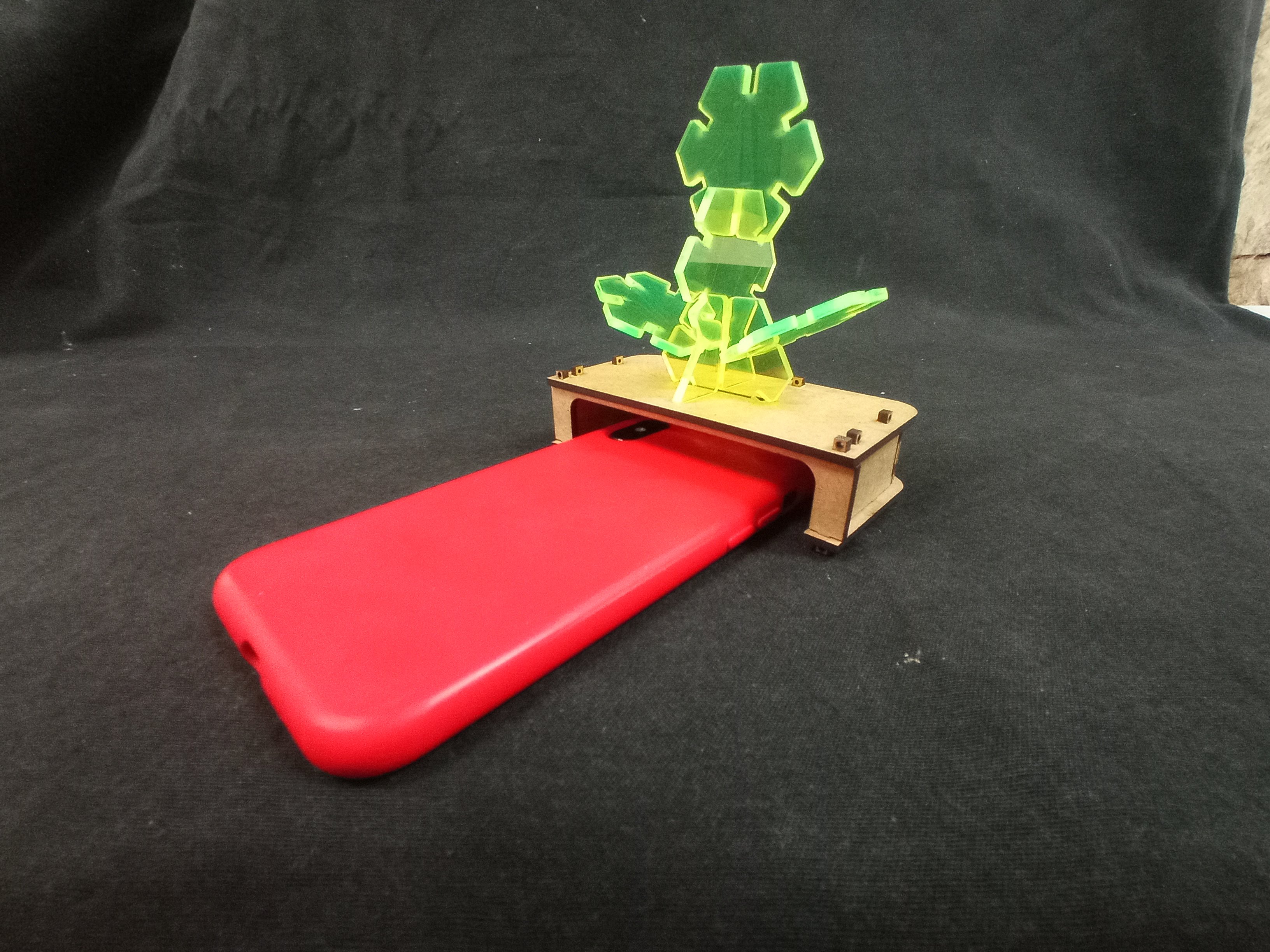
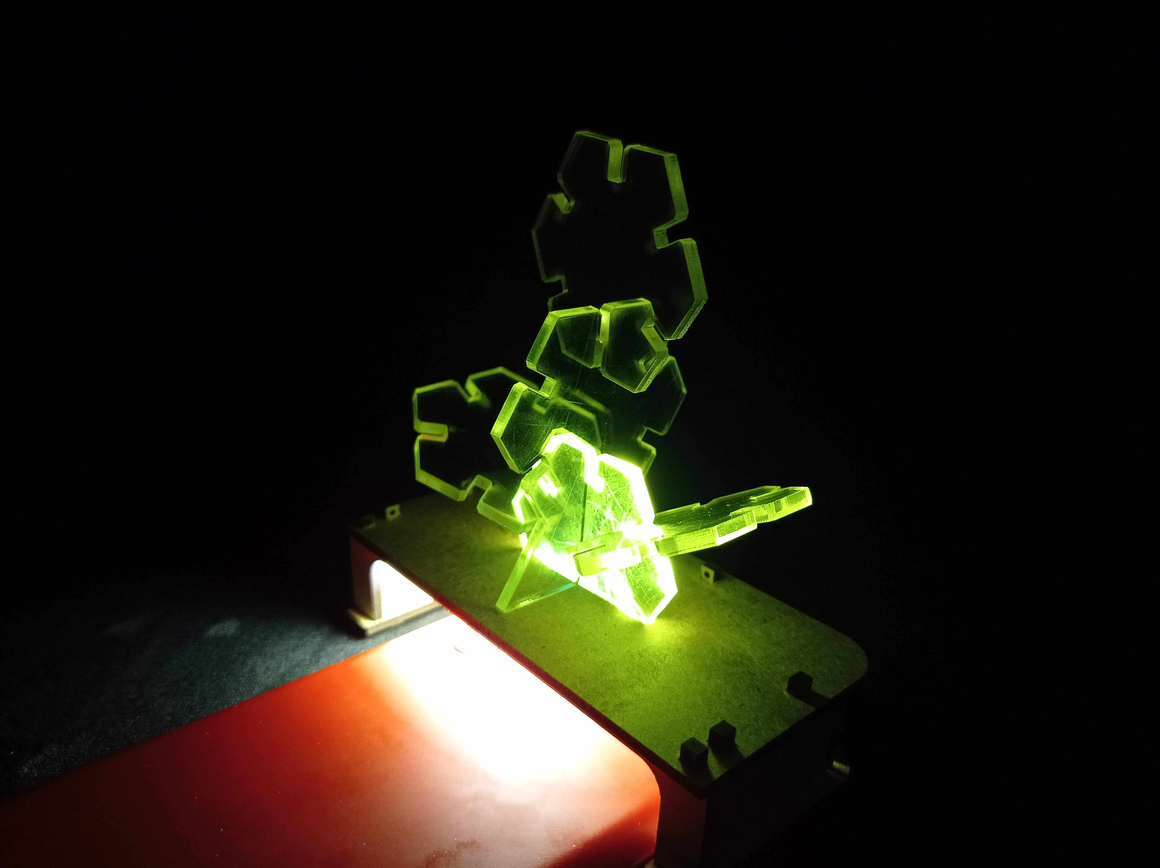
Thinking about creating a parametric constiction kit I came out with the idea to make a modular Lamp that works with your the phone light.
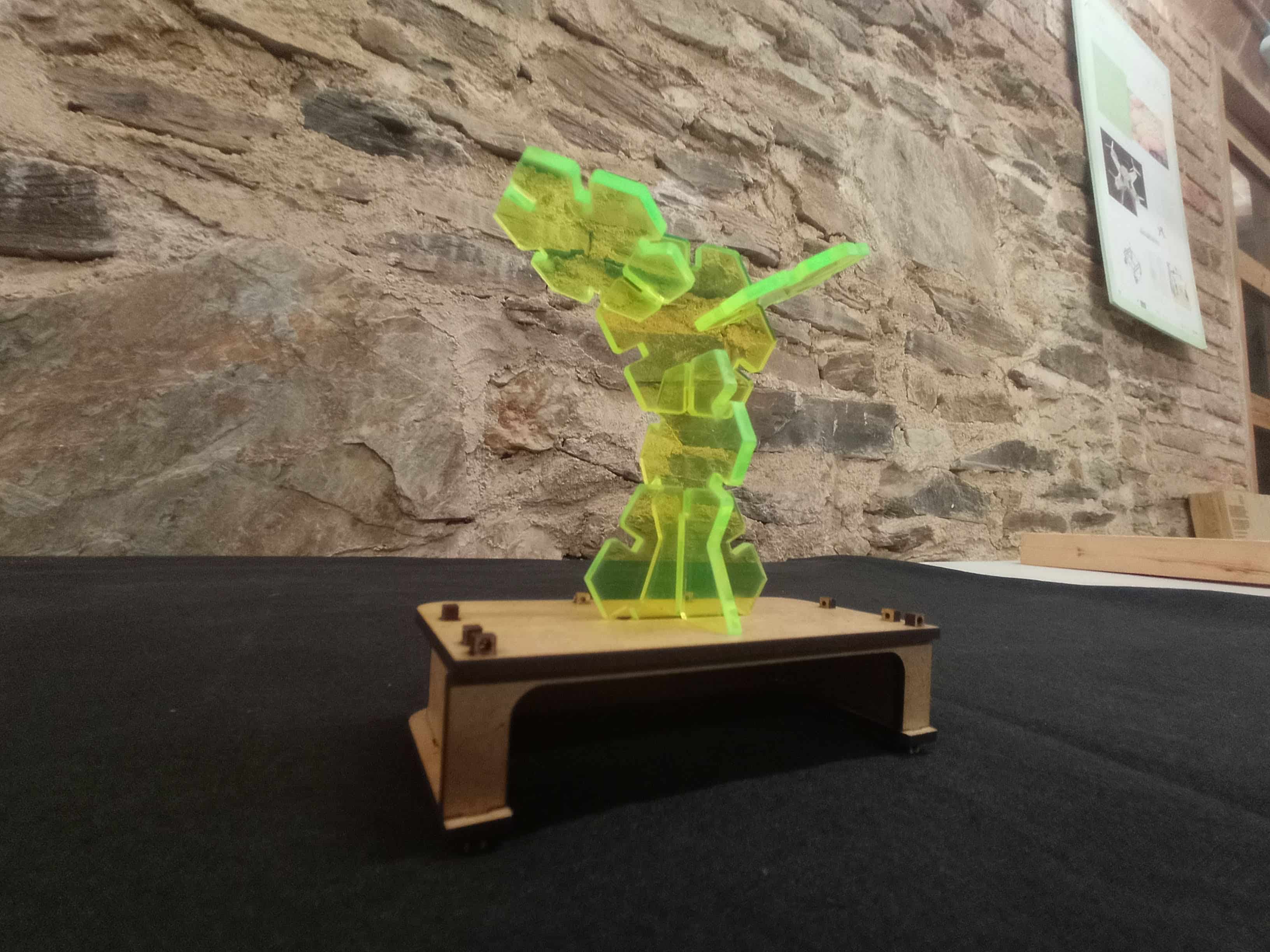
To achieve that, first of all, using Fusion360 I've designed an editable geometry to create the reflecting and modular pieces of the lamp.
With som of that pieces you can build the the 3D shape that you like most.
in the Gif, you can see how the pice can be modified changing the value of the differnt parameters.

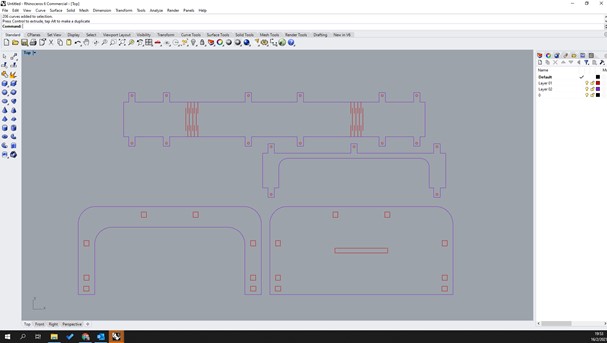
On the Other hand, I've designed whith Rhino6 a box wher all the pieces are attached to.
I've Made the box in MDF bacause is a non trasnslucent material and also I had som scrap pieces that where perfect to use.
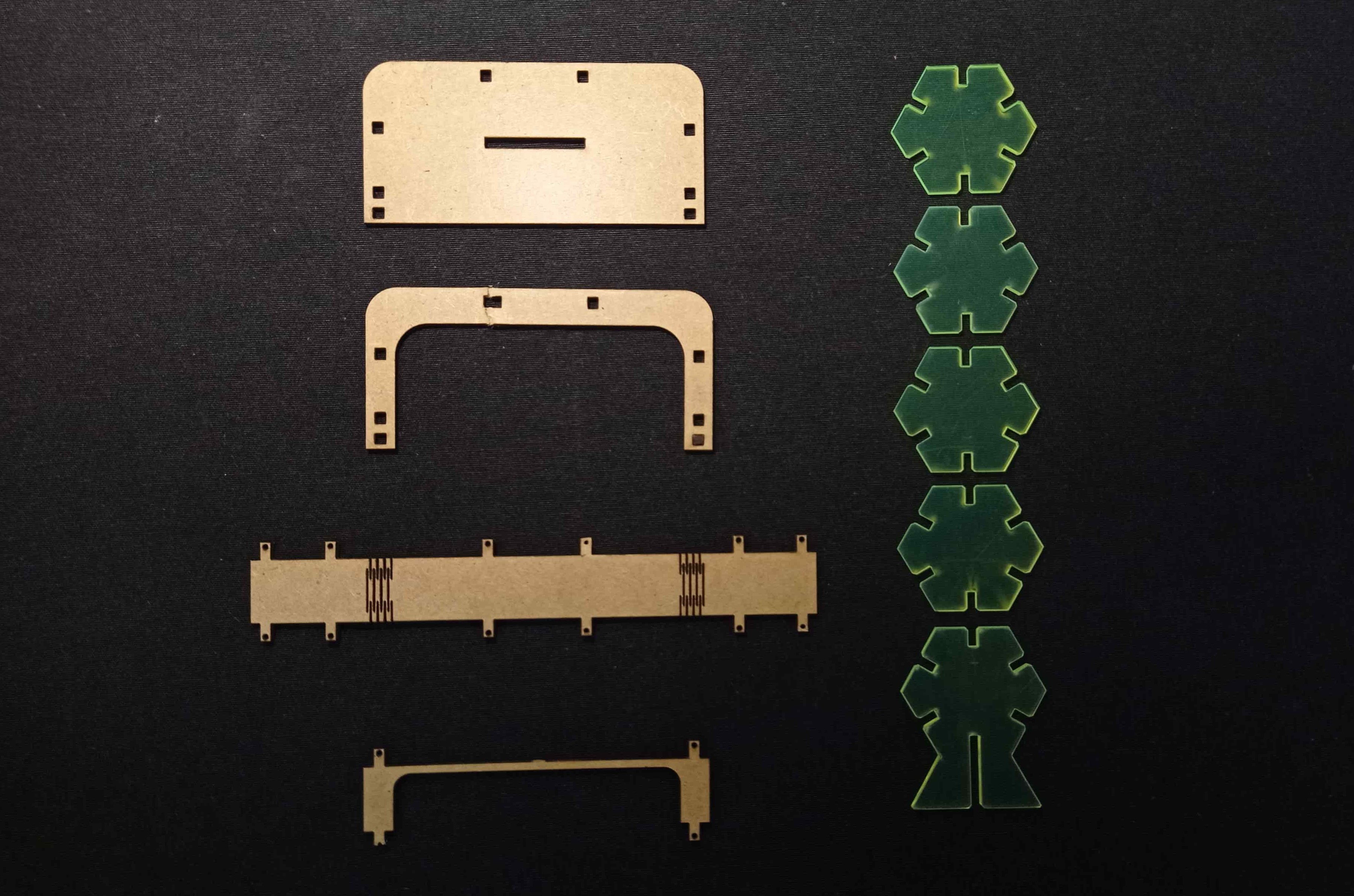
Finally here, you can see the exploded parts.
The assembly process.

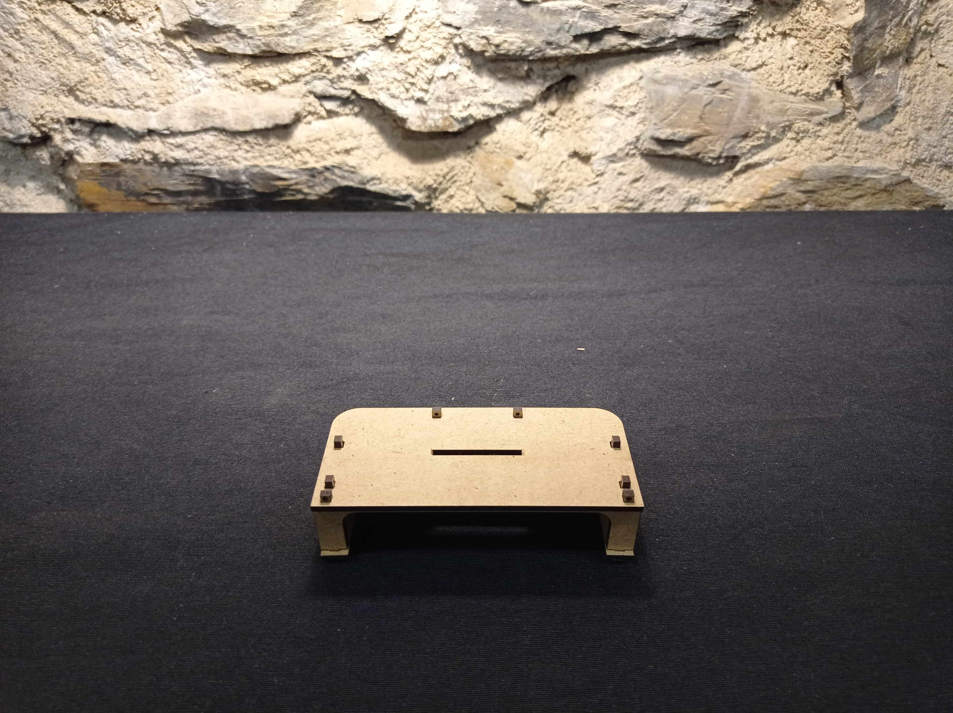
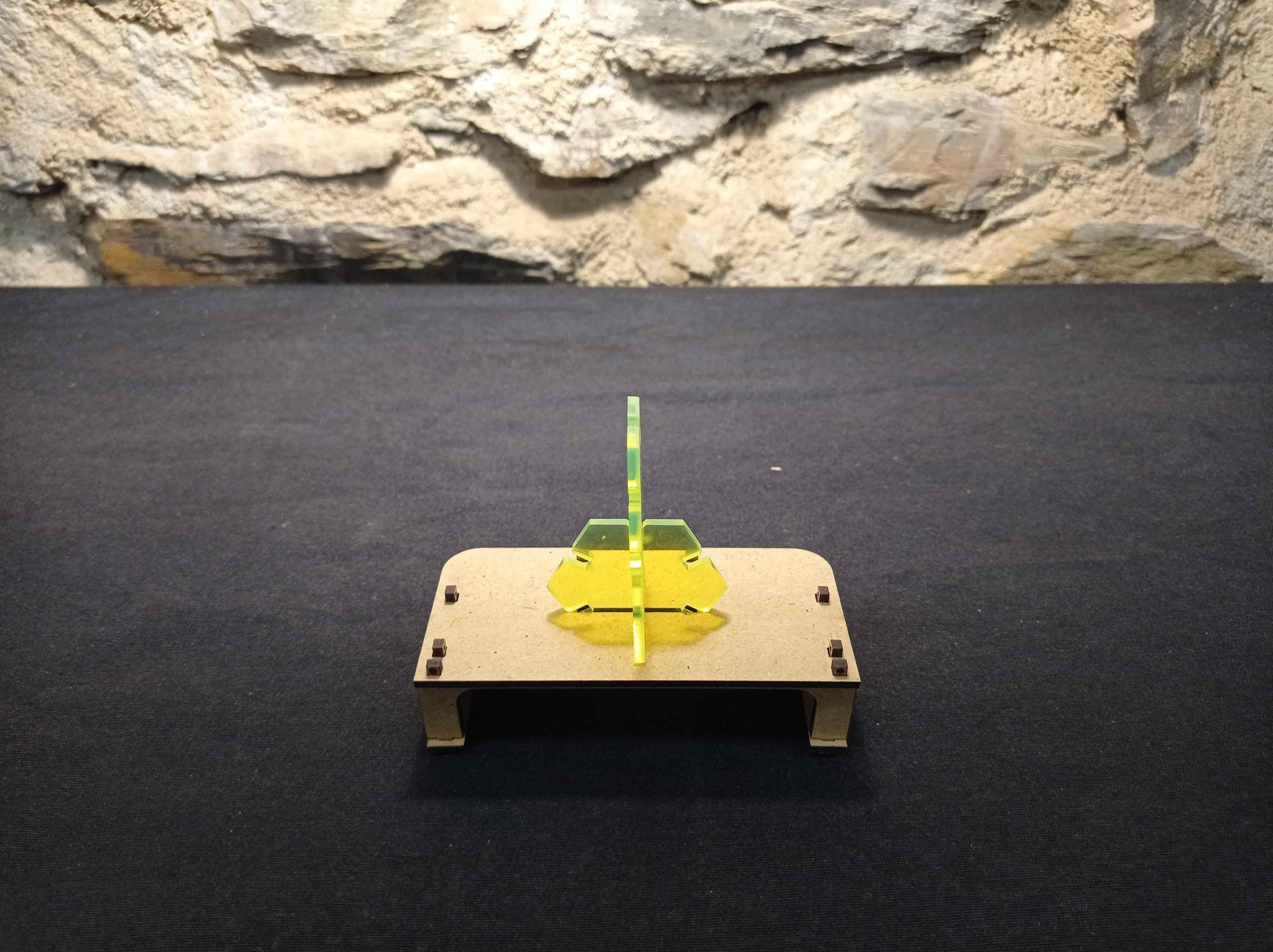
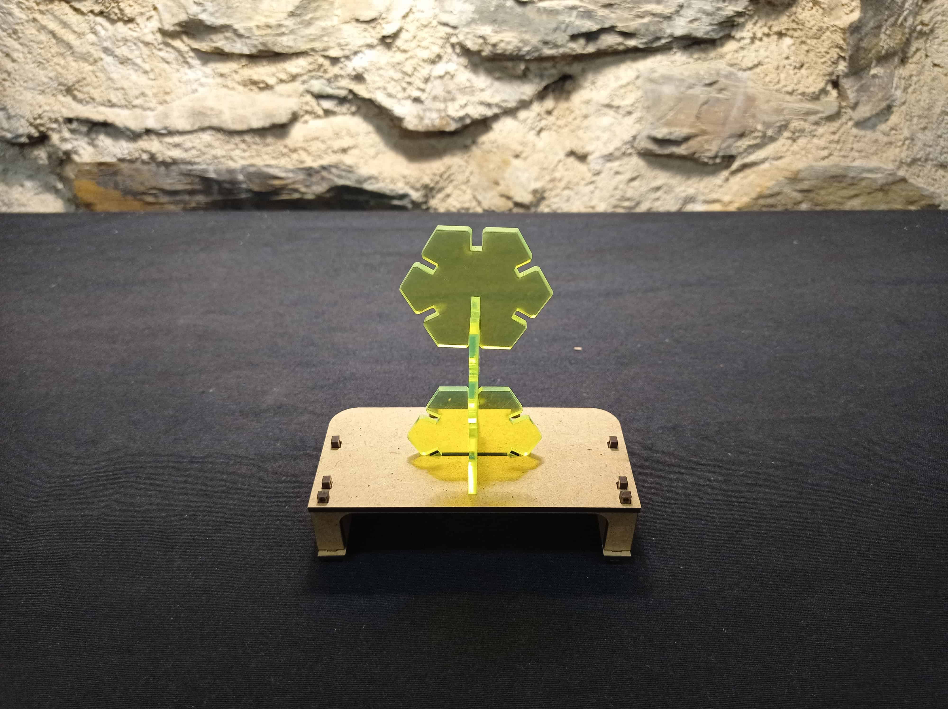
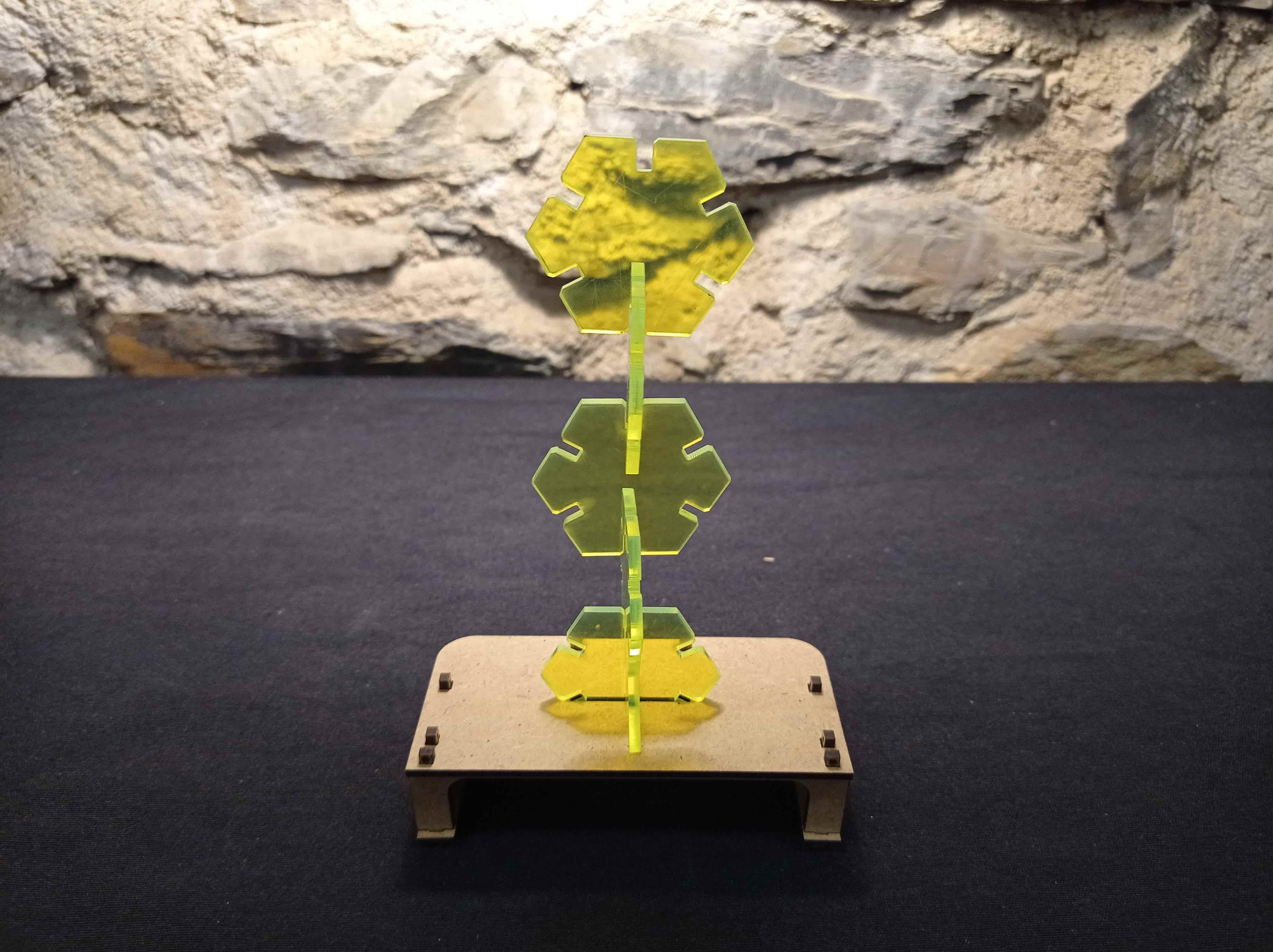
And the Final Result.
Files
Find in the link the files of this assignment
FINAL COMENTS
THINGS TO IMPROVE.
- One think that it would have been better it's the kerf definition because in the final result as you can see in the GIF the pieces are a bit loose.
- The reflection of the pieces is not a proper one.