Final Project:
Adaptative color lamp
I consider light as a vehicle to convey feelings, not just a tool to see. It is curious that, for example, no one is comfortable in totally dark spaces. Even when you know the space (your house for example) you don't decide to go to the bathroom in the dark. You turn on a light that, although not very powerful, allows you to feel more comfortable.
The concept that I would like to study revolves around the actuation of light. We are used to having an on / off switch or maximum a potentiometer. Why not go further and try to create a more pleasant experience than flipping a switch?
Actions such as stroking, screaming, burning, blowing, , whistling, soaking, hitting… make me think of lighting systems that make us feel more connected to light. I would like to create a more animal experience with lighting. Can I create a pleasant experience around interacting with a system? Can we interact with light in a more elemental, more animal way?
Related projects
Here you will find a small list of reference projects from the interactive part of the light system:
| Name | Link |
|---|---|
| Fluid Current | https://www.instagram.com/p/CKOJVaXAcFn/ |
| Candle Lamp | https://www.instagram.com/p/CJ-wOXRAQMQ/ |
| Wilhelm | https://www.instagram.com/p/CJVlXejAkZ-/ |
| Bloom | https://www.instagram.com/p/CHzuPAyA8FC/ |
| Ball Lamp | https://www.instagram.com/p/CC-pbulDLpa/ |
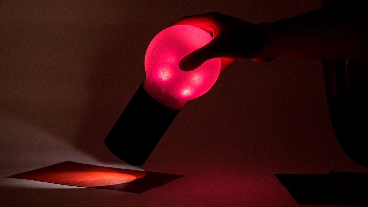
CONCEPT
It's funny because I had never thought of a lamp that copied color until a few weeks ago. But all of a sudden it seems that everything around me is pushing me towards the idea. From ads on the internet recommending similar products, to Neil presenting a similar project in one of his classes. While I did not abandon the initial idea of interacting with light in ways other than on / off switches, I think that focusing on the concept of copying light is a good base from which to start the spirals.
Let me start by explaining the general idea of the product:
Idea
"The idea is to make a lamp that acquires the color that the user wants. But not by means of a remote control or an app but by reading colors thanks to a sensor. In addition, the interaction with the lamp escapes from the current domestic interactions with electronic systems. "
Keeping the product summed up in one sentence is a strategy I learned in college that always helps me focus my head on what I'm doing. Hope it also helpsyou fully understand what I am willing to develope.
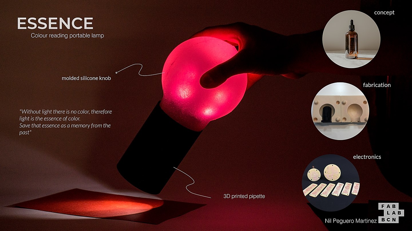
"To be able to refer to the old dropper bottle of medicines and perfumes from the beginning of the 20th century. The memory of apothecary bottles, reinterpreted as a bottle of color essences. Save the chromatic memory in the form of light. The essence of color."


References
Here are some references of similar projects that apply color reading to the lighting sector:
| Name | Link |
|---|---|
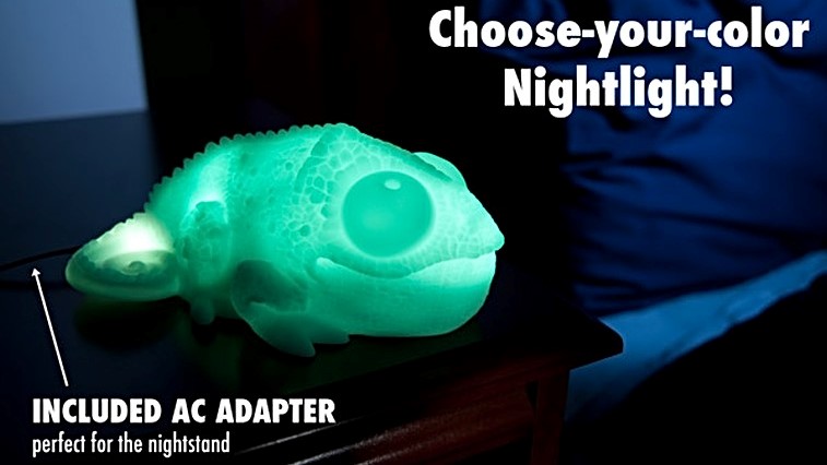
| Huey the Chameleon | https://www.vat19.com/item/huey-color-copying-chameleon-lamp |
| Magical Colour Lamp | https://www.instructables.com/Magical-Chameleon-Lamp/ |
| High-performance Color Detector | https://www.instructables.com/High-performance-Color-Detector-for-Under-1/ |
Theoretical basis
To begin, I want to understand the operation and theoretical concepts on which light control is based. You have to take into account several concepts of optical physics that I think are interesting to develop the project, under control.
The first concept we must understand is "Why do we see colored things and why those colors?". To understand this concept better, let's look at the following graphic
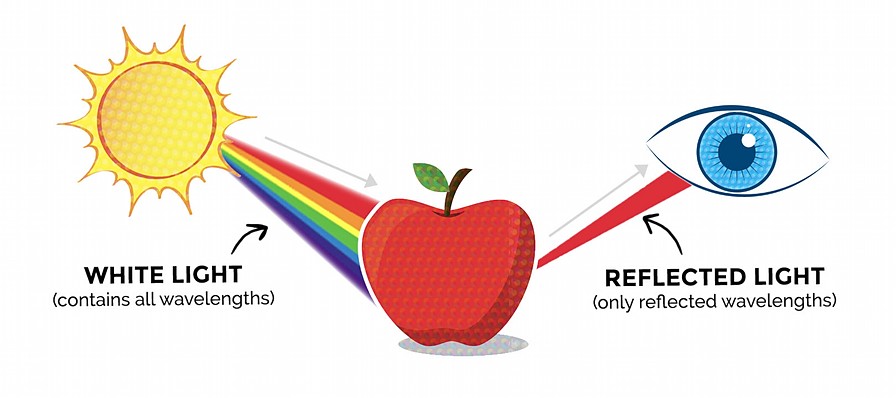
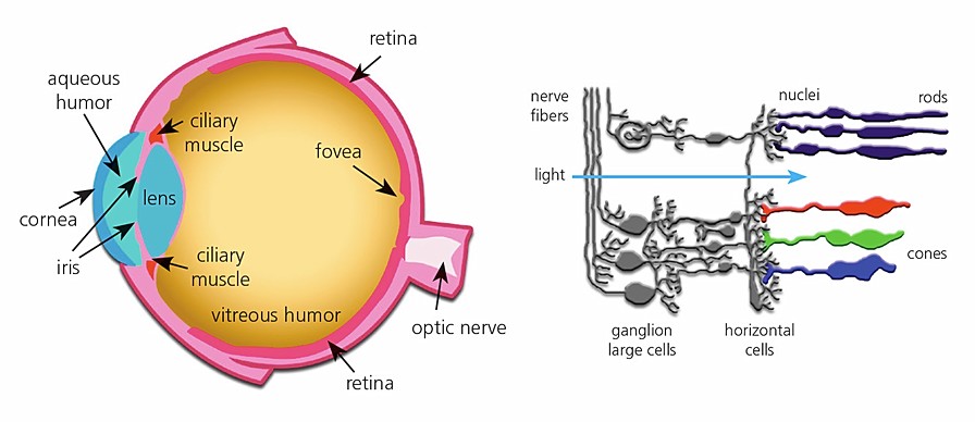
Light is, in a simplified way, a wave, so the color change is produced by the wavelength at which the wave vibrates. Objects absorb all colors, except the color that we see that is reflected towards our eyes. All the waves added generate the white color (only in additive color) so that when we bounce off the object we lose part of the light spectrum and we only see the reflected that enters our eyes.
Another concept to understand is how our eye (which is still a sensor but biological) transforms the length of one it receives into information. Inside the eye we have cells called Cone Cells, which are capable of understanding the colors that objects reflect.
The sensitivity of our eyes to light is relevant for the project, since we have to be able to read colors within the spectrum of light that our eye can understand. Because of the advancement of electronics, we are currently able to read spectra of light outside of our capabilities. The visible spectrum of light that our eye can see is the following.
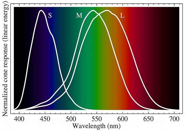
For a better conclusion of this point, we draw the following conclusions after understanding the two previous graphs and the next one.

Conclusions
- White light contains all wavelengths within the visible spectrum.
- The matter that receives the light, absorbs all the lights except the one we see, which is reflected towards our eyes.
- The spectrum of light visible to humans is 380 to 750 nm, and under perfect conditions it is 310 to 1050 nm. We start to look at purple and reach up to red.
- The optimal points of view are, for each color within RGB: R (570nm), G (540nm) and B (440nm).
- The sensor that we use for the project must have an optimal behavior between 400-600nm to be able to appreciate it in the best way with the eyes.
DESIGN APPROACH
As an industrial designer and engineer, I believe that the process is the most important thing in creativity, therefore I would like you to see the design process that I have followed to develop this project.
In order not to take too long explaining the steps that I have followed, I summarize the creative work of the last few months in 3 great tools:
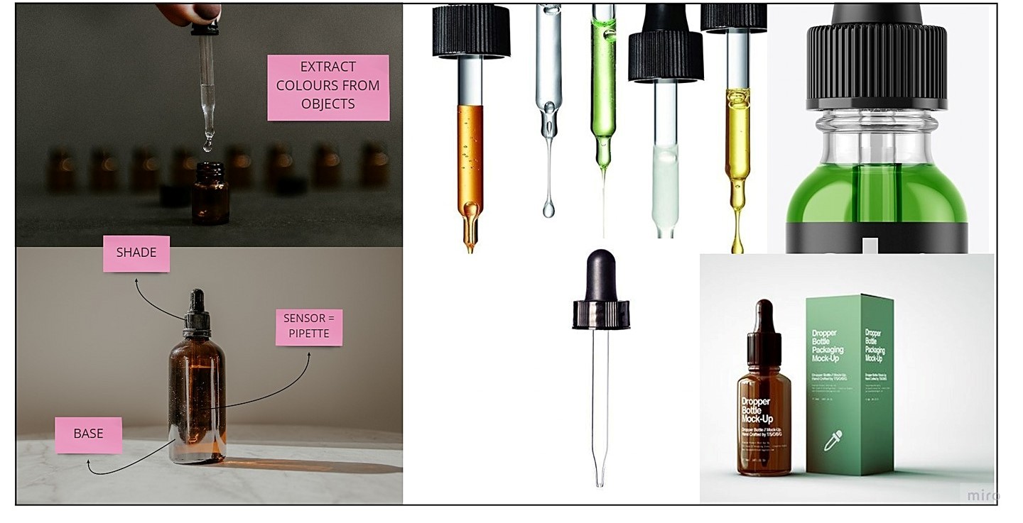
MOODBOARD
Basically I use this visual tool to always have at hand the elements that make up my idea and the reminders that I want to generate with the product when interacting with it. It's a great way to never lose sight of the essence of the project.
SKETCHES
Pen and paper are always a powerful creativity tool. There is no better way to express ideas than through a drawing. It is even useful for the designer to clarify ideas for himself.
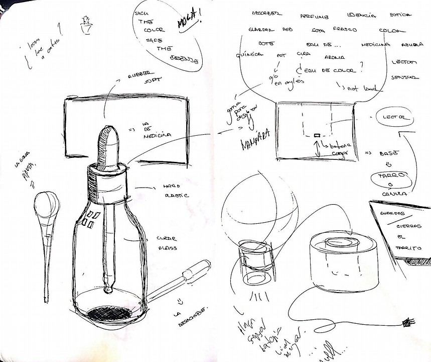
I have made dozens of sketches, but I think this reflects better than any other the concept I work on and where each of the pieces that generate the project come from.
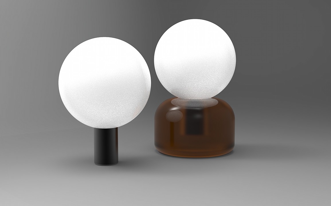
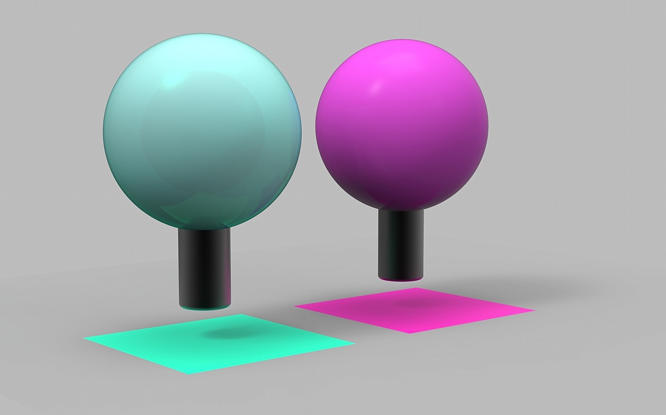
RENDER
CAD rendering is the last of the tools for the visual process of creativity. It allows you to finally see what the product looks like once it is finished. If it is well worked it is like a flashforward of what the device should look like.
.I have chosen these two so that you can see the comparison between a render worked (the first) and one made in a few minutes to simply clarify my ideas.
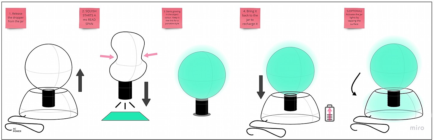
USER EXPERIENCE
As I have already been telling you little by little on this page, the idea is to take the interaction with the product to the next level. For this I think that the first branch I have to talk to you about is the interaction between user and product.
To create the sensation of absorbing color through a dropper, we have to ensure that the sensation and interaction with the lamp and the dropper is as close as possible.
Once the work of generating the idea is finished, it is time to create it. So we started with electronics.
ELECTRONICS
As I have already explained to you during the weeks of electronic assignment, this has been the great discovery for me. I have never had a chance to learn how to design electronics before and have ended up enjoying it more than any other topic.
For this chapter of the final project I would like to show you all the PCBs that I have developed, their functions and how they interact with each other.
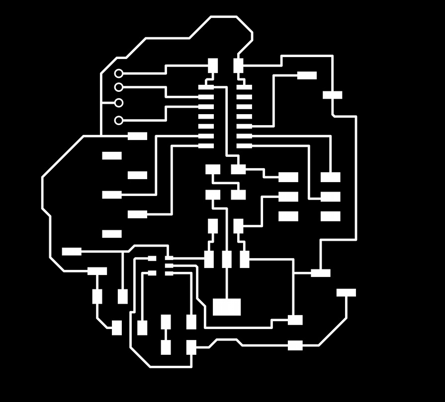
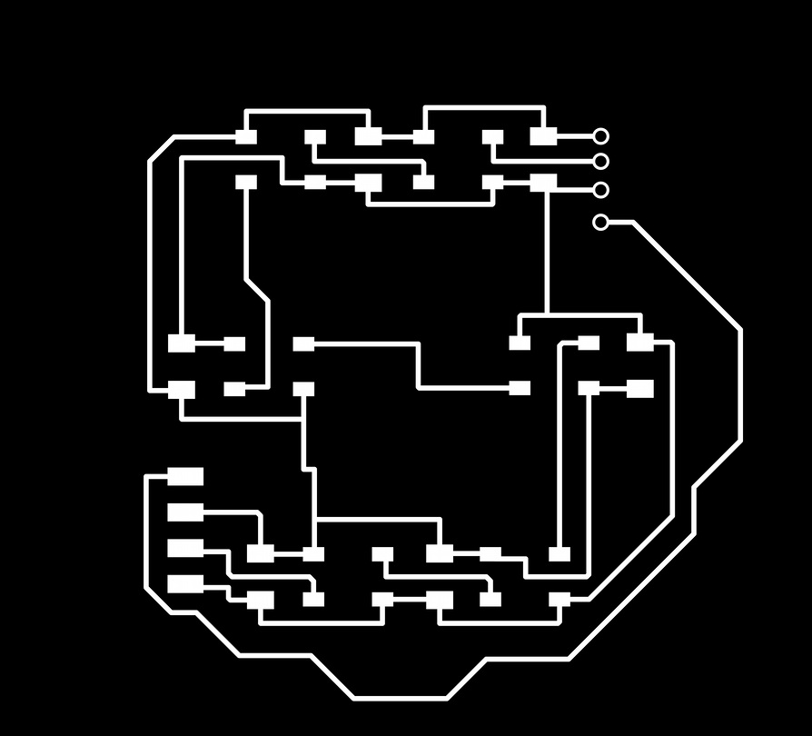
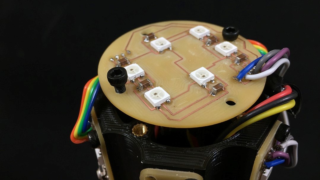
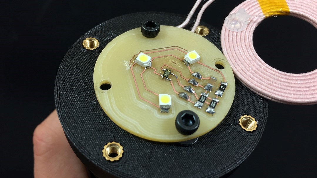
MAIN BOARD
We start with the most complex PCB in the entire electronic system. In this case, this board is a mix of a main board, a charge manager and a neopixel system.
Its function consists of housing the microcontroller and its peripherals, checking that the battery charge is correct and the upper neopixels are responsible for lighting the upper part of the silicone screen.
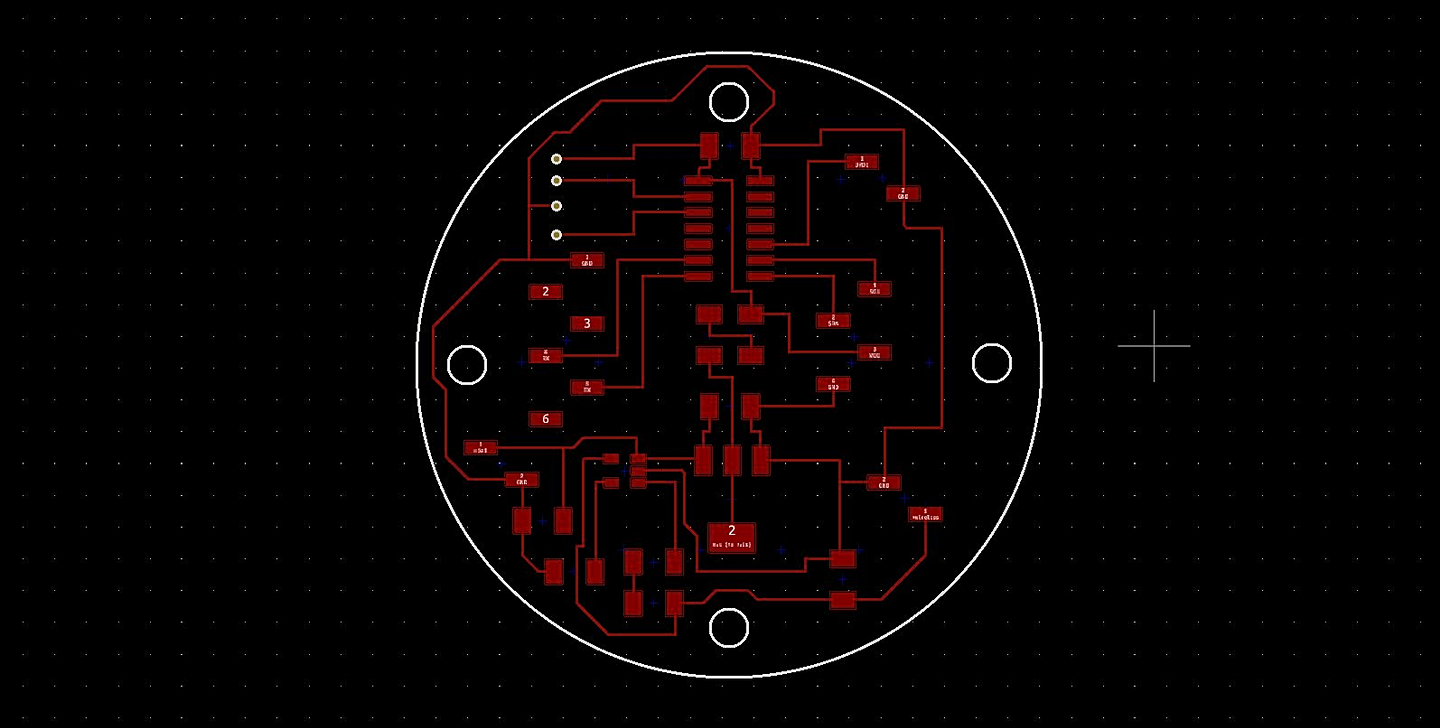
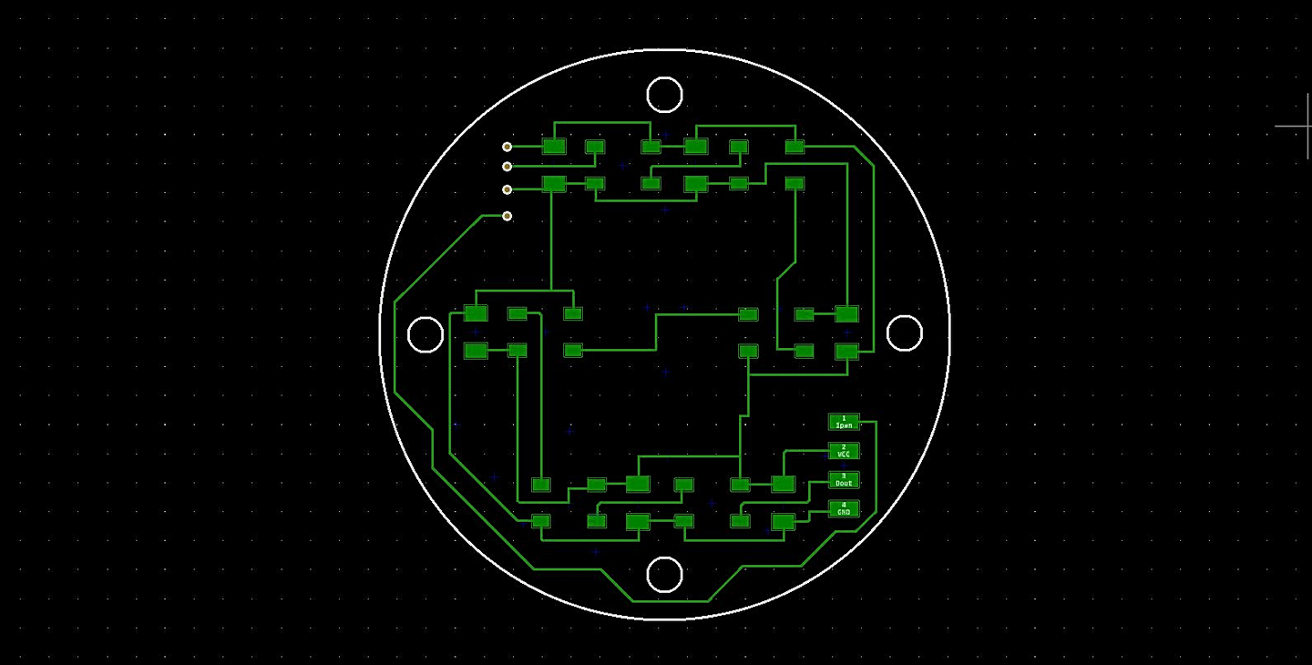
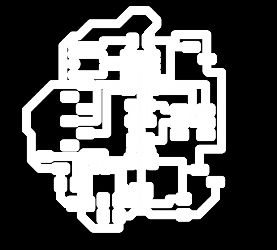
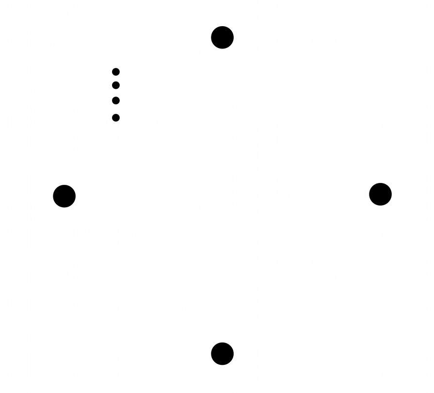
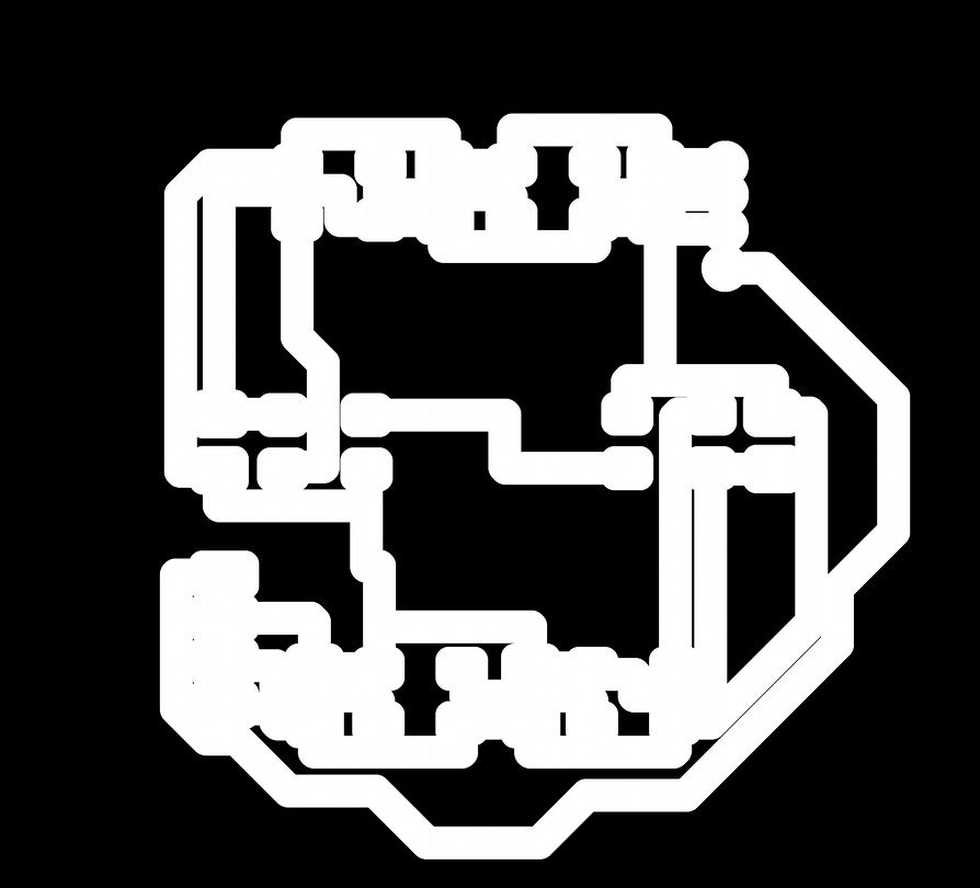
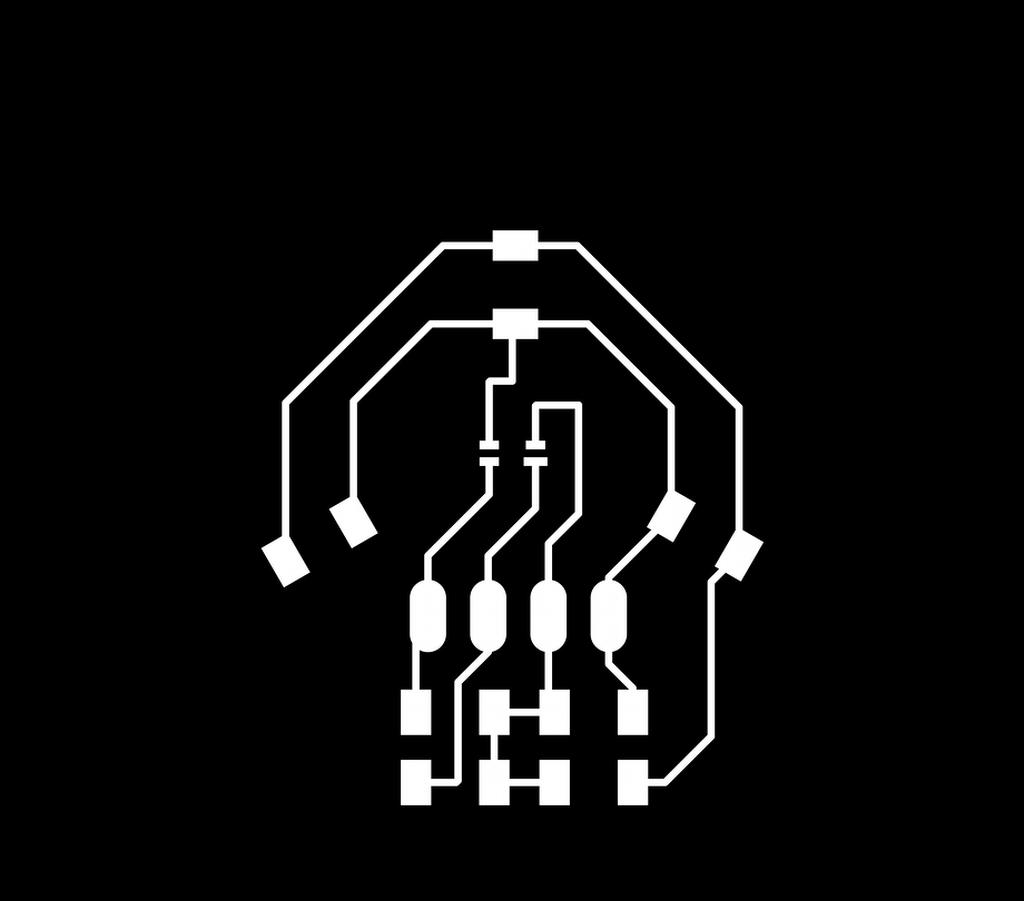
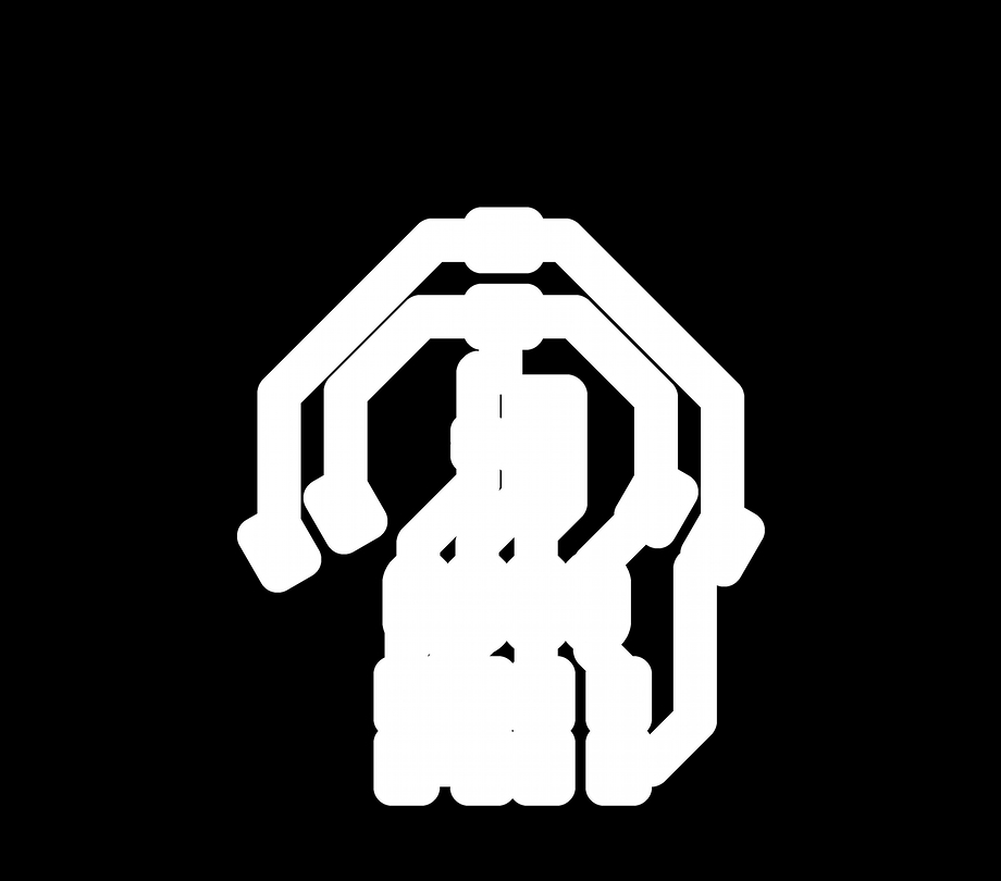
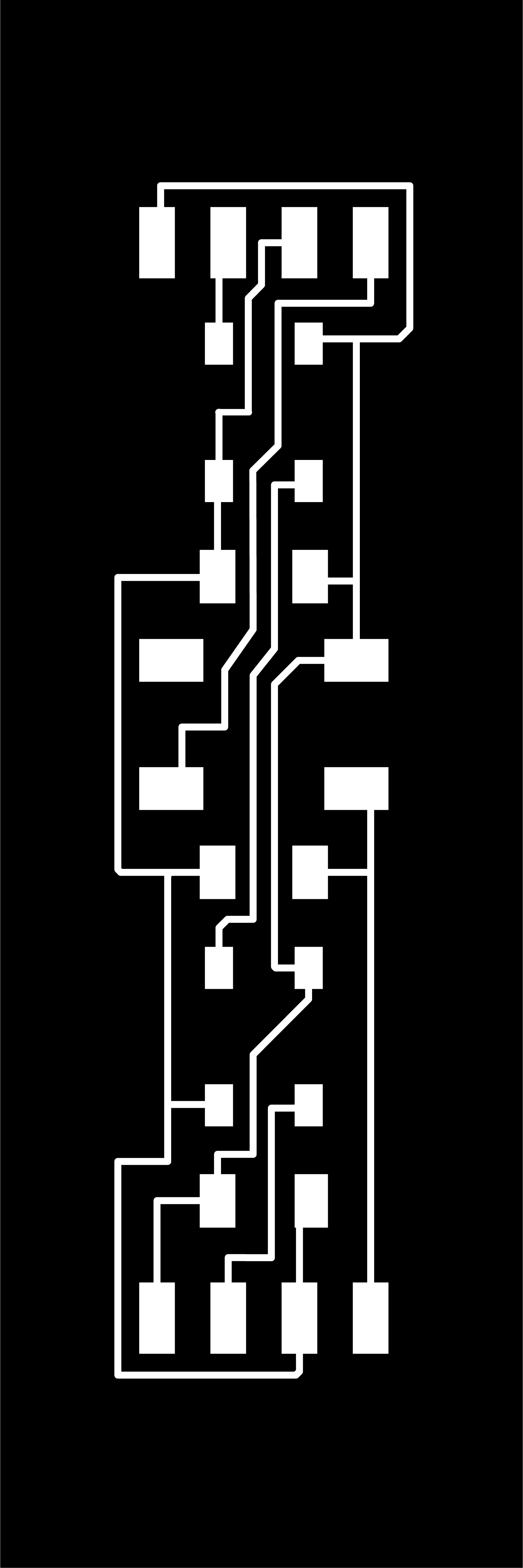
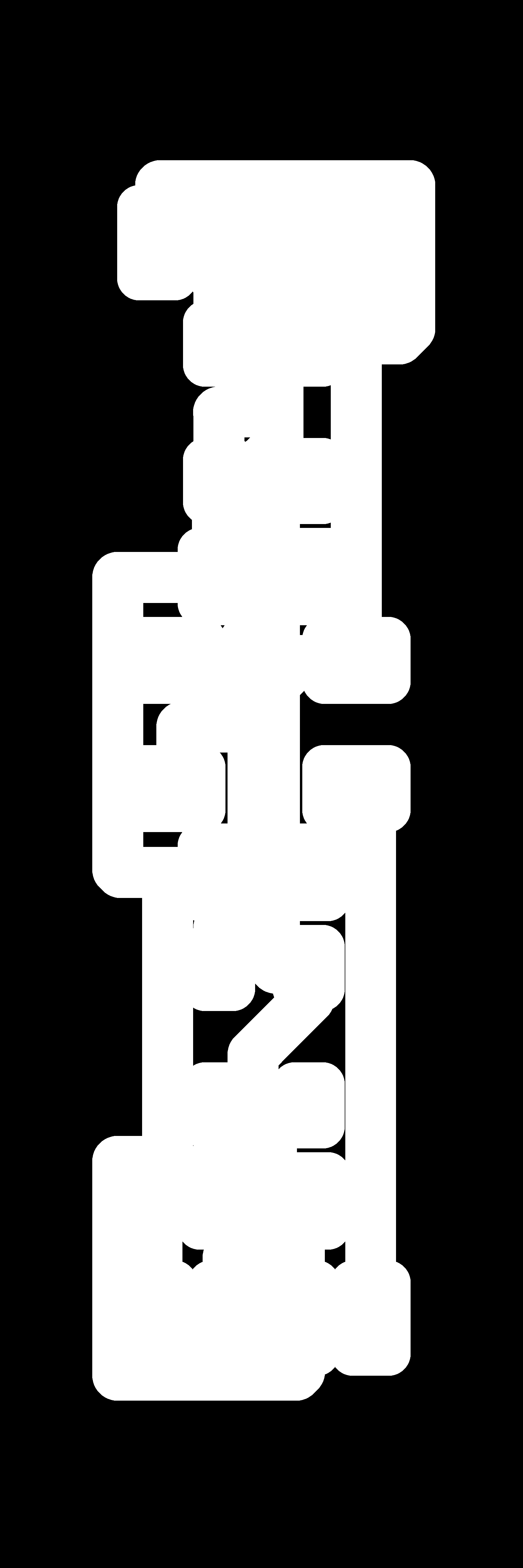
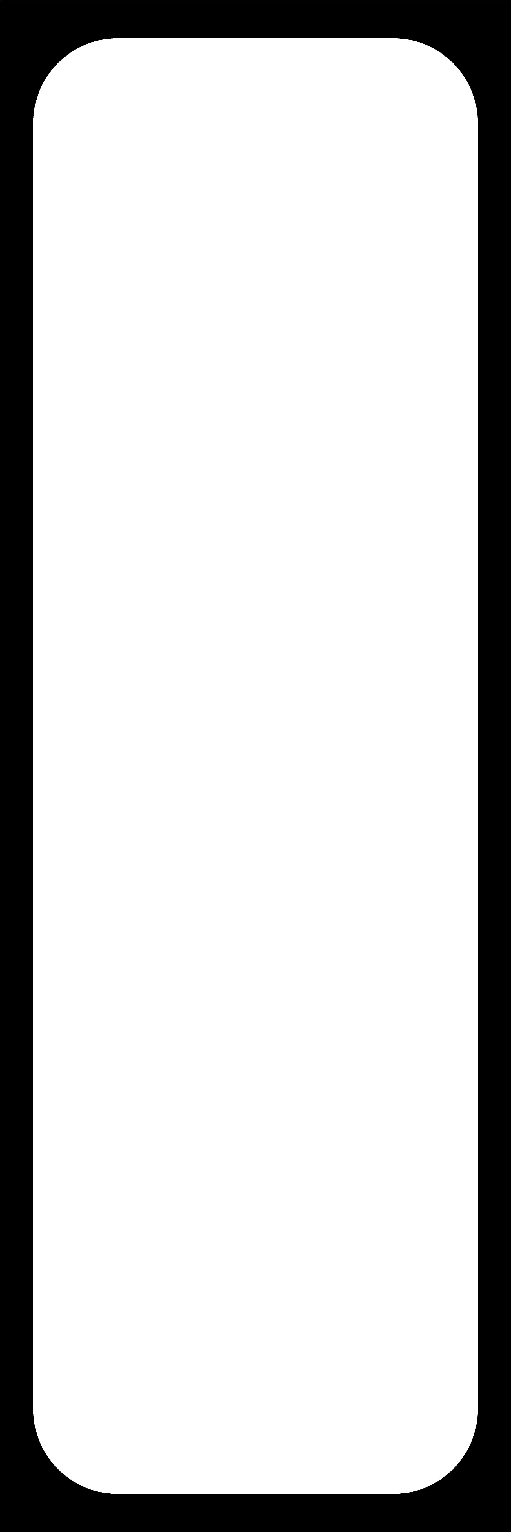
With the Kicad finished, we have to prepare the png files for use in ModsProject. In the following list you have all the necessary steps to mill this PCB.
- Front traces 1/64"
- Front fill 1/32"
- Front holes 1/32"
- Front interior 1/32"
- Back traces 1/64"
- Back fill 1/64"

Once the PCB is ready, we place the vias and add a little soldering so that they do not move.
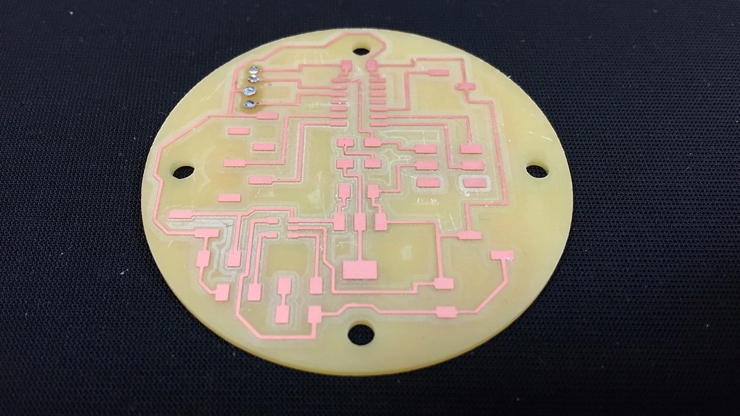
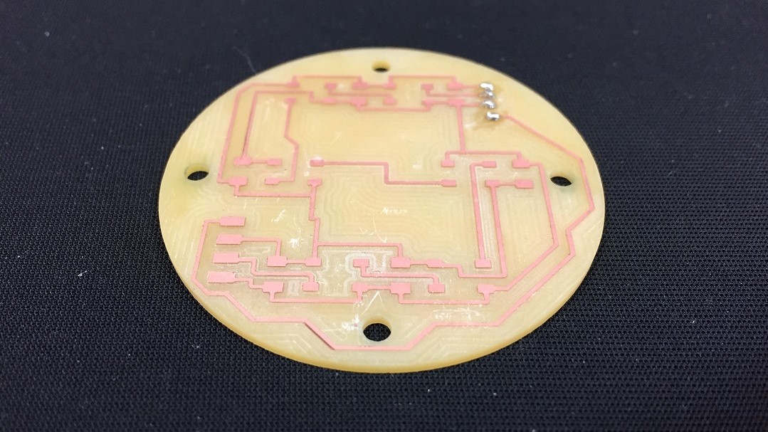
After collecting the various components and soldering them in position, here is the finish on the top of the PCB.
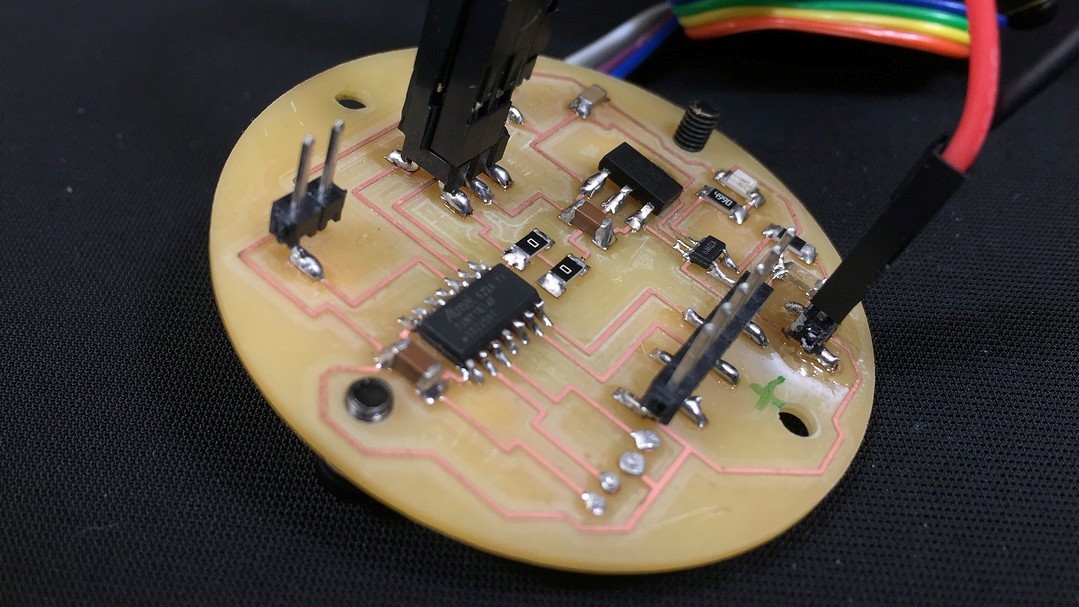
Lastly, but where the PCB difficulty really lies, here is the already wired final result of the bottom of this mainboard.
SENSOR BREAKOUT
Compared to the Main Board, this PCB is straightforward, but it has its quirks. For you to see the process of being I will use the same system as with the other: Kicad, png's and final results.


With the Kicad finished, we have to prepare the png files for use in ModsProject. In the following list you have all the necessary steps to mill this PCB.
- Traces 1/64"
- Fill 1/32"
- Sensor traces 0.010"
- Holes 1/32"
- Interior 1/32"

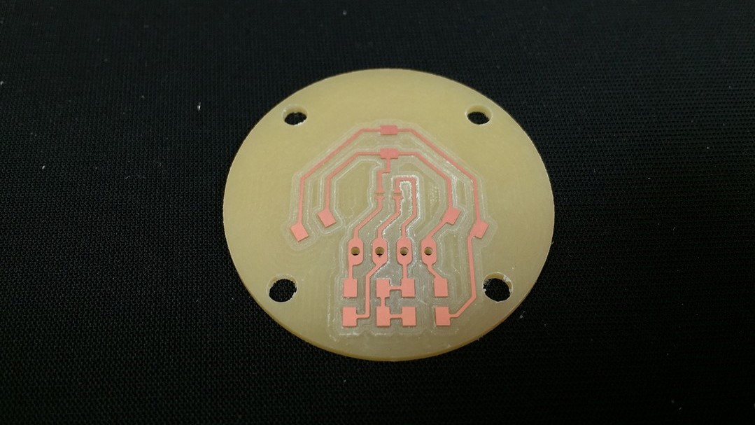
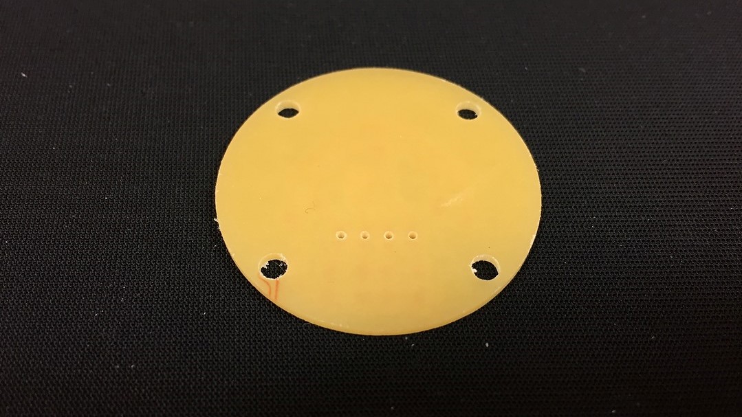
In the same way as in the Input week, the sensor has been soldered by reflow soldering and the rest of the component by manual soldering iron.
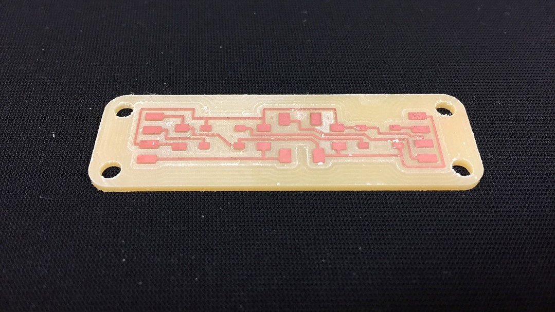
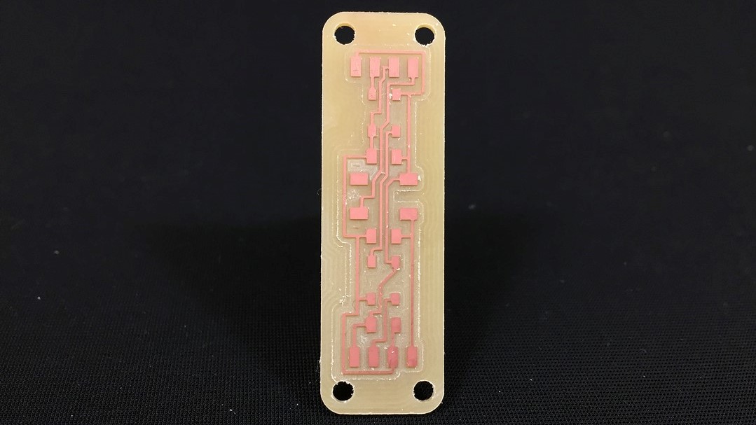
SIDE BOARDS
These are the simplest PCBs in the entire lamp, but they are a lot (6). Next we do with the other PCBs, production process. Its function is to illuminate the sides of the screen and house the buttons that are pressed when the silicone is pressed.


With the Kicad finished, we have to prepare the png files for use in ModsProject. In the following list you have all the necessary steps to mill this PCB.
- Traces 1/64"
- Fill 1/32"
- Holes 1/32"
- Interior 1/32"

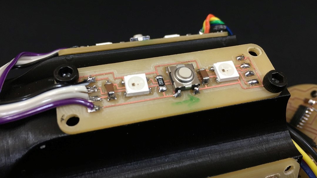
Now the only thing left is to solder all the components in position and test that all the circuits work correctly.
CODE
In this new section of the project development we focus on the code that controls the entire system. Here is the code as I have uploaded it to ATTiny1614, then I will comment on it to explain in general terms what functions it does:
#include Adafruit_NeoPixel.h>                                                // Include NeoPixel library
#ifdef __AVR__                                                                // ???
#include avr/power.h> // Required for 16 MHz Adafruit Trinket               // ???
#endif
#include "Wire.h"                                                             // Include I2C Library
#include "veml6040.h"                                                         // Include Color Sensor library
VEML6040 RGBWSensor;                                                          // change sensor name for an easier one

int redColor;
int greenColor;
int blueColor;

int r;
int g;
int b;

int red;
int green;
int blue;

// constants won't change. They're used here to set pin numbers:
const int buttonPin = 1;                                                      // the number of the pushbutton pin
#define PIN        0                                                          // pin number for data to NeoPixel
#define NUMPIXELS  18                                                          // the number of Led's you have
#define DELAYVAL   1                                                          // time (in milliseconds) to pause between pixels


// variables will change:
Adafruit_NeoPixel pixels(NUMPIXELS, PIN, NEO_GRB + NEO_KHZ800);               // the number of the pushbutton pin
int buttonState = 0;                                                          // variable for reading the pushbutton status
int RedColor = 0;                                                             // variable for reading Red color (starting it at 0)
int GreenColor = 0;                                                           // variable for reading Green color (starting it at 0)
int BlueColor  = 0;                                                           // variable for reading Blue color (starting it at 0)


// Configuration aspects of the code
void setup() {
  Serial.begin(9600);                                                         // initialize Serial Monitor at 9600 bauds
  pinMode(buttonPin, INPUT);                                                  // initialize the pushbutton pin as an input:
  pixels.begin();                                                             // initialize NeoPixel strip object (REQUIRED)

  Wire.begin();                                                               // initialize I2C communication
  if (!RGBWSensor.begin()) {                                                  // if can't ind sensor do this...
    Serial.println("ERROR: couldn't detect the sensor");                      // print the message in serial monitor
    while (1) {}                                                              // do that for a second
nsor.setConfiguration(VEML6040_IT_320MS + VEML6040_AF_AUTO + VEML6040_SD_ENABLE); // configurate the sensor (comes from the library)
  delay(1500);                                                                            // wait for 1,5s for good configuration
  Serial.println("Vishay VEML6040 RGBW color sensor auto mode example");                  // print the message in serial monitor
  Serial.println("CCT: Correlated color temperature in \260K");                           // print the message in serial monitor
  Serial.println("AL: Ambient light in lux");                                             // print the message in serial monitor
  delay(1500);                                                                            // wait for 1,5s again before loop
}

// code that repeats itself in time
void loop() {

  buttonState = digitalRead(buttonPin);
  Serial.println(buttonState);
  redColor = RGBWSensor.getRed();                                     // define variable to read the state of the button in X pin
  greenColor = RGBWSensor.getGreen();                                 // define variable to read the state of the button in X pin
  blueColor = RGBWSensor.getBlue();                                   // define variable to read the state of the button in X pin
	/*
  Serial.print("RED: ");                                              // print the message in serial monitor
  Serial.println(RedColor);                                             // print the value for red variable
  Serial.print(" GREEN: ");                                           // print the message in serial monitor
  Serial.println(GreenColor);                                           // print the value for green variable
  Serial.print(" BLUE: ");                                            // print the message in serial monitor
  Serial.println(BlueColor);                                            // print the value for blue variable
	*/

  redColor = RGBWSensor.getRed();
  r = map(redColor, 5800, 41700, 0, 255);
  greenColor = RGBWSensor.getGreen();
  g = map(greenColor, 6800, 65535, 0, 255);
  blueColor = RGBWSensor.getBlue();
  b = map(blueColor, 3710, 20500, 0, 255);

  r = constrain(r, 0, 255);
  g = constrain(g, 0, 255);
  b = constrain(b, 0, 255);


  Serial.print("RED: ");                                              // print the message in serial monitor
  Serial.println(r);                                             // print the value for red variable
  Serial.print(" GREEN: ");                                           // print the message in serial monitor
  Serial.println(g);                                           // print the value for green variable
  Serial.print(" BLUE: ");                                            // print the message in serial monitor
  Serial.println(b);

  if (buttonState == HIGH) {                                                              // check if the pushbutton is pressed. If it is, the buttonState is HIGH:

    pixels.clear();                                                             // Set all pixel colors to 'off'

    for (int i = 0; i < NUMPIXELS; i++) {                                    // For each pixel... (starts at 0 an keeps adding LED's
      // pixels.Color() takes RGB values, from 0,0,0 up to 255,255,255
      pixels.setPixelColor(i, pixels.Color(r , g , b));                    // use variables R,G,B as numbers from 0-255
      pixels.show();                                                              // Send the updated pixel colors to the hardware.

      delay(DELAYVAL);                                                            // Pause before next pass through loop (0.001s = despreciable)
    }

  } else {                                                                                //when the button is not pressed... LOW
    //Serial.print("RED: ");                                                               // print the message in serial monitor
    //Serial.print(RedColor);                                                              // print the value for red variable
    //Serial.print(" GREEN: ");                                                            // print the message in serial monitor
    //Serial.print(GreenColor);                                                            // print the value for green variable
    //Serial.print(" BLUE: ");                                                             // print the message in serial monitor
    //Serial.print(BlueColor);                                                             // print the value for blue variable
  }
}
Aunque casi todas las lineas estan comentadas en el mismo código a continuación tienes un pequeño listado secuencial de todo lo que sucede dentro de mismo.
- All the necessary variables are defined, we include the necessary libraries and we define the pins that the microcontroller will use
- We start the setup: define the button as input, start the serial monitor, start the pixels, start the I2C communication, start the sensor and wait 1.5s
- We start the loop: reading the button in digital and passing it to serial monitor, we obtain the readings of R, G, B in wavelength previously to the calibration
- We calibrate the wavelength data to digital signal 0-255. I'll tell you more in the next point
- When the buttons are pressed, the previous color is cleaned, and the new reading is sent to the pixels through three signals R, G, B (one per color)
CALIBRATION
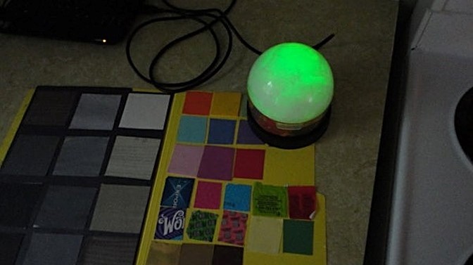
This is the important part of this chapter, I do not consider that the code is too complex, but the calibration of this sensor is. In my case, I have considered that understanding what values the sensor sends and being able to convert it to a digital signal is the first step so that the colors are similar.
To see how I have calibrated the sensor, below you have a small table of values taken in different ambient lights to understand how it affects the sensor.
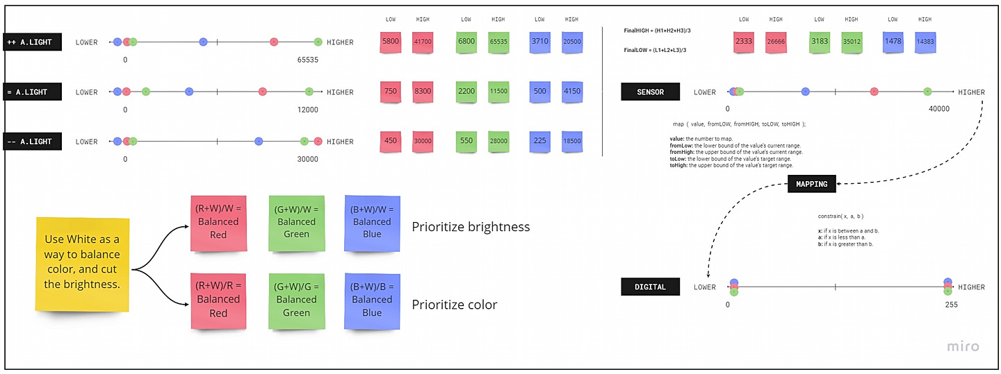
In broad strokes, calibration consists of taking the highest and lowest measurements of each color in different light conditions. Average these readings and use the map () and constrain () functions to go from wavelength to digital signal.
- map (), allows us to convert the wavelength range to a range from 0 to 255.
- constrain (), converts values greater than 255 and those less than 0, thus always obtaining a meaningful value.
In the future, I would like to get the sensor calibrated with a more professional system. For now, I consider that this is not bad code for FabAcademy, but it is far from being as perfect as I would like.
MANUFACTURING
Now we enter the chapter of the manufacture of the mechanical parts that make up the different parts of the lamp. To give a certain order to the point, we will review the pieces that make it up one by one.
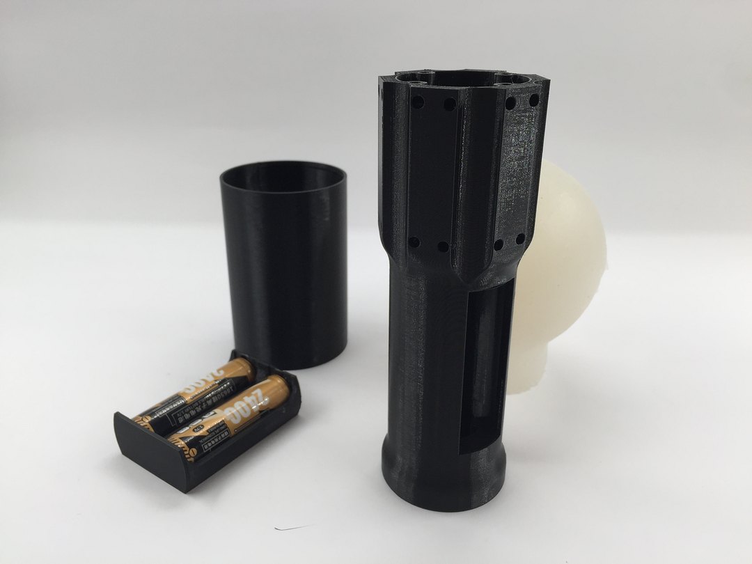
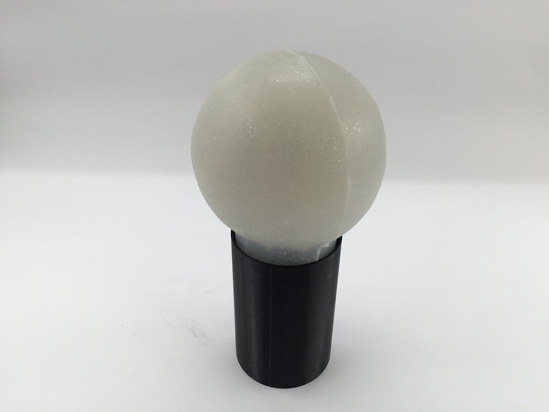
PIPETTE
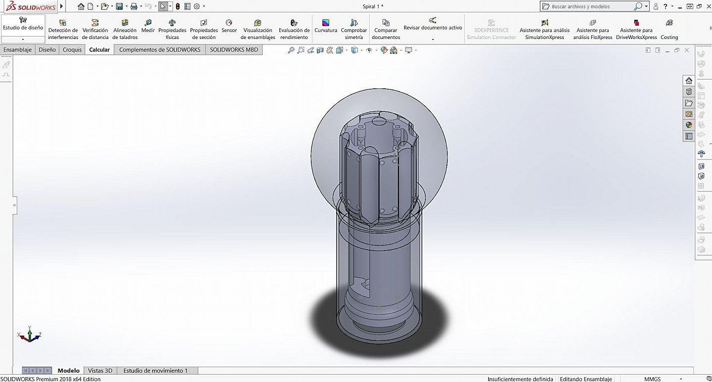
The first part I want to talk to you about in manufacturing is the most important in my eyes: the pipette. This is the central structure of the lamp, the one that holds all the components in position and the one that provides the fulcrum for the entire product.
It is also the one that has cost the most to design, the number of restrictions to take into account are many and they all had to be perfect: measurements of the pcb, measurements of the batteries, fit with the knob, screws ...
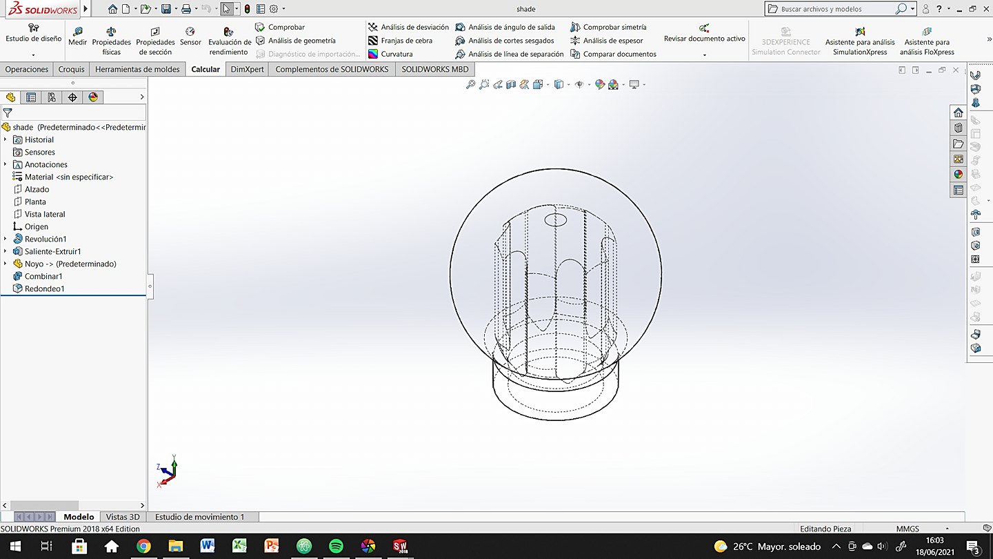
Once all the general appearance of the piece had been modeled (in Solidworks) it was time to plan the preparation for a correct impression. There were several trials and errors, until I finally managed to create the correct supports and overhangs so that there were no defects.
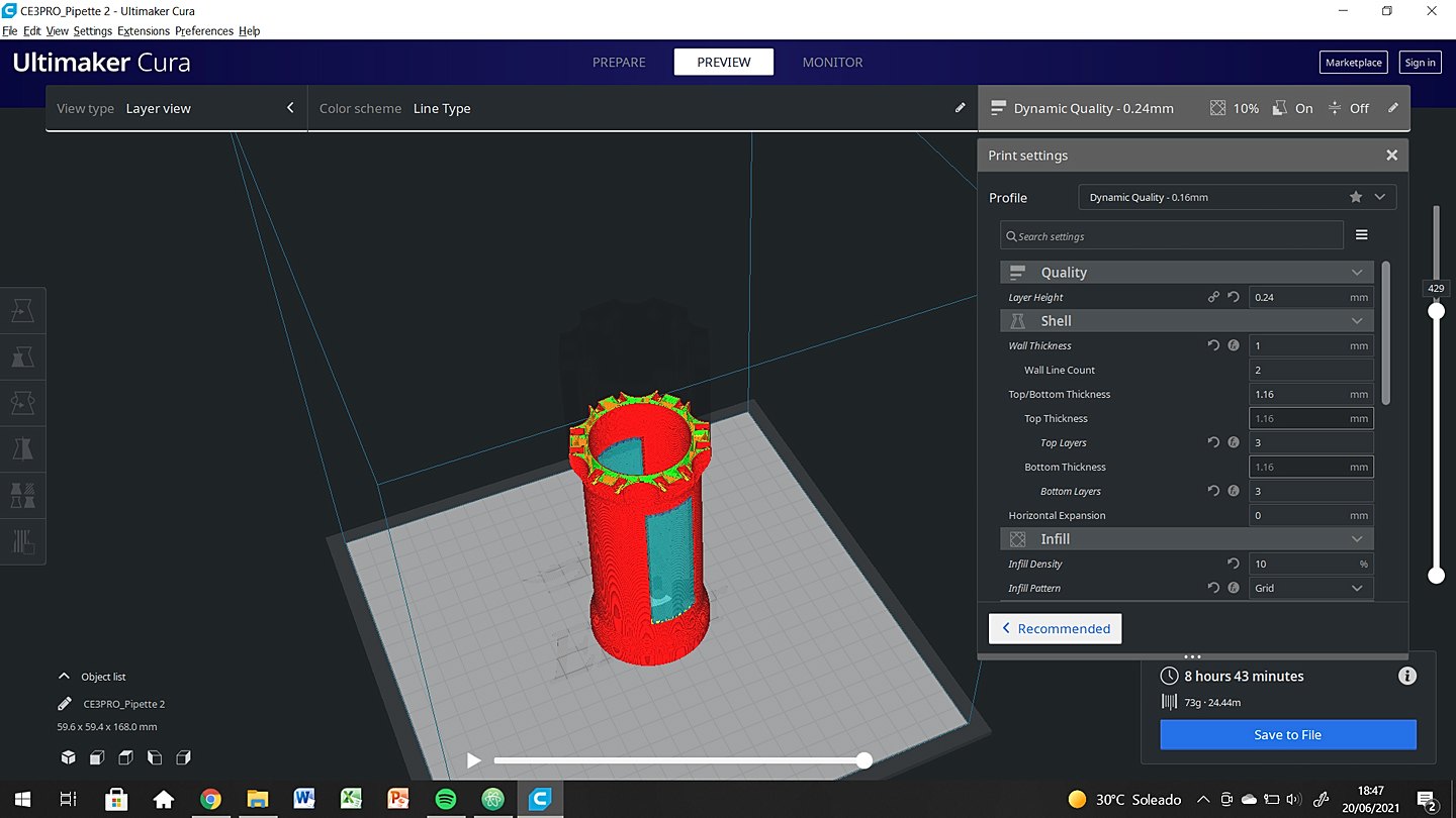
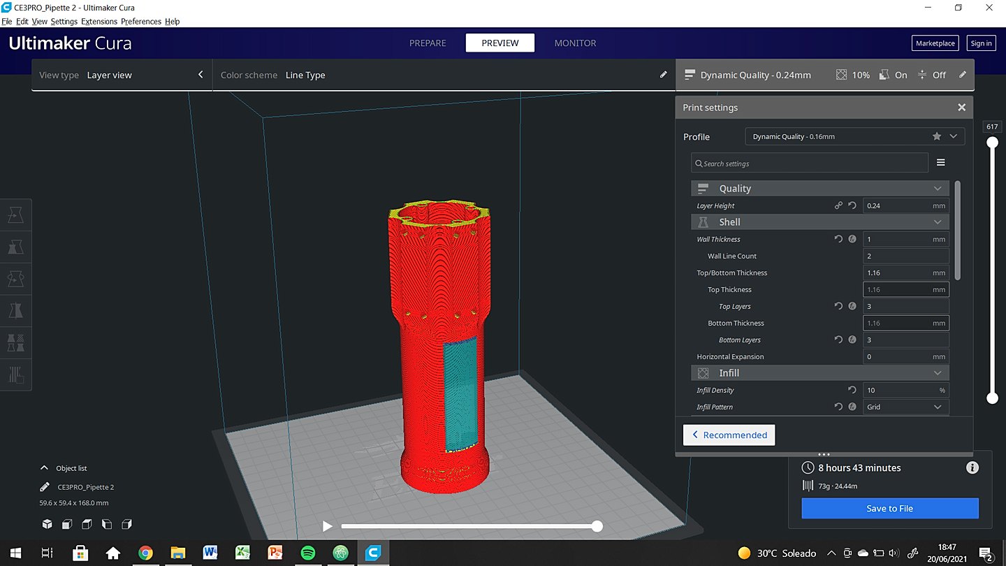
Everything worked fine, after 3 wrong prints without supports or with too much overhang. Let me tell you about the next part that makes up this piece and I show you the results of the printing.
This piece has a lower cover, which simultaneously acts as a trim, support for the inductor and fit with the knob. This piece was actually easy to model, it is still a glass with a rim. In the following images you have the modeling process of the piece.

After printing the files on the Creality Ender 3 in Black PLA, the result was as follows:
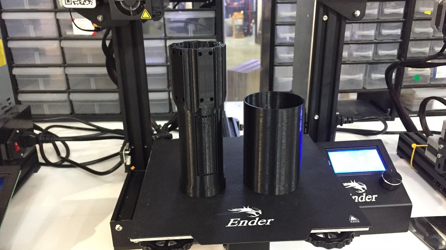
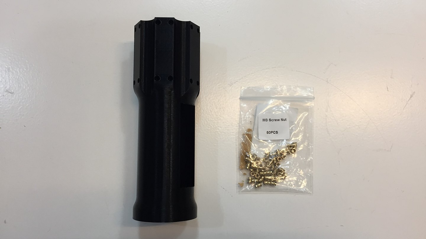
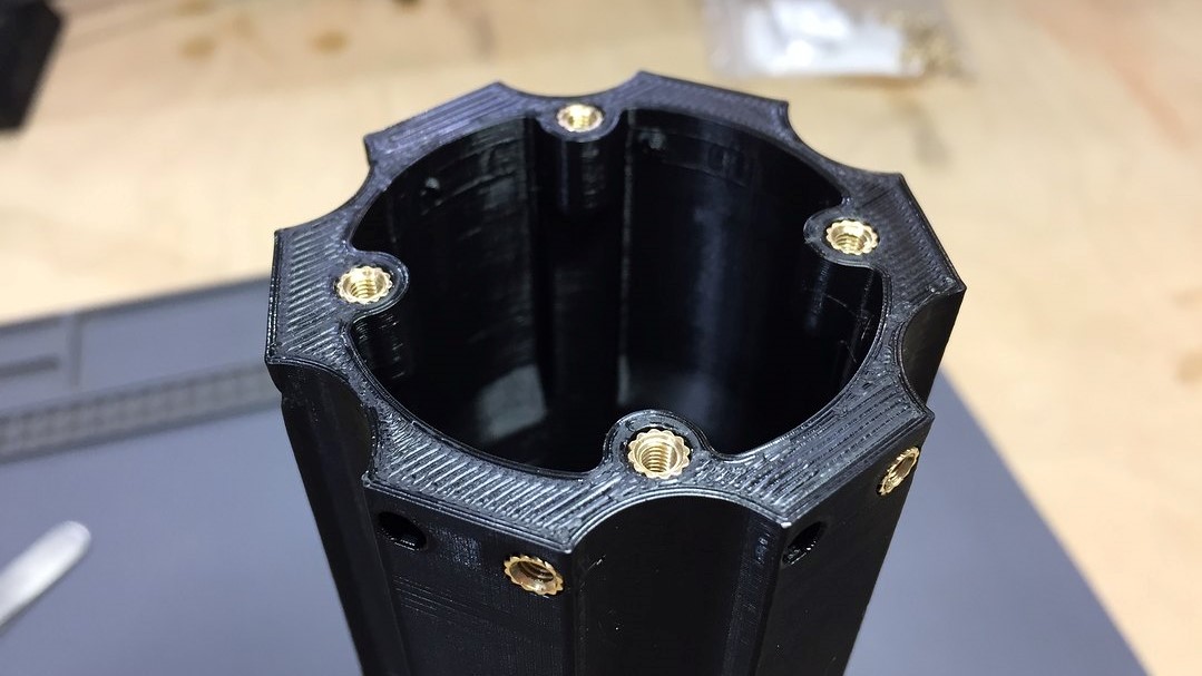
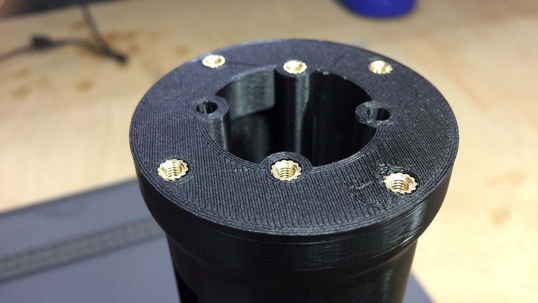
After many brass inserts later, the fit was correct and all the modules fit correctly where they should.
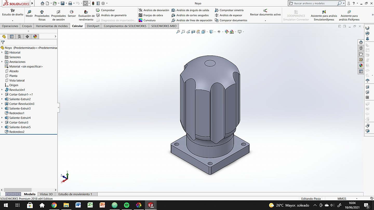
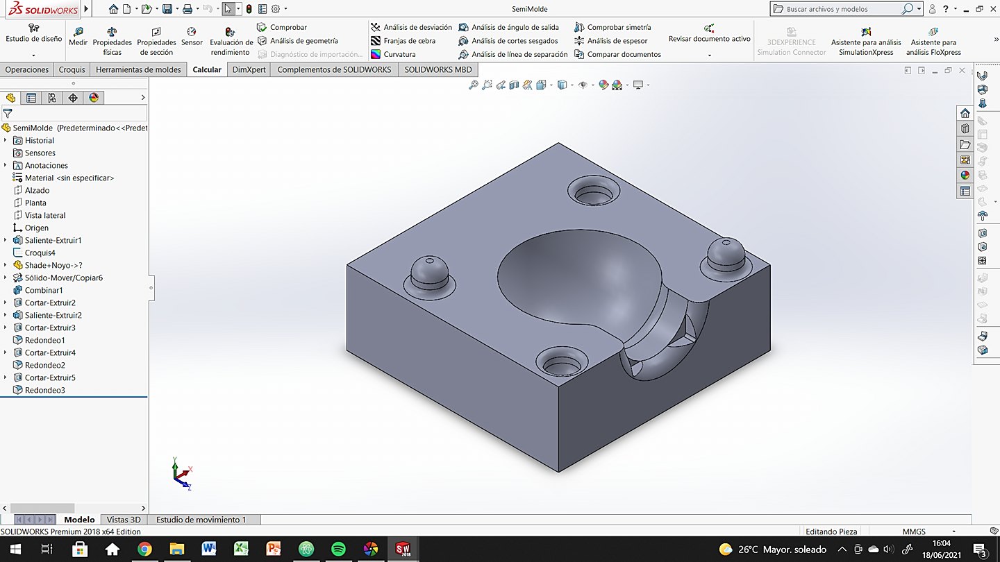
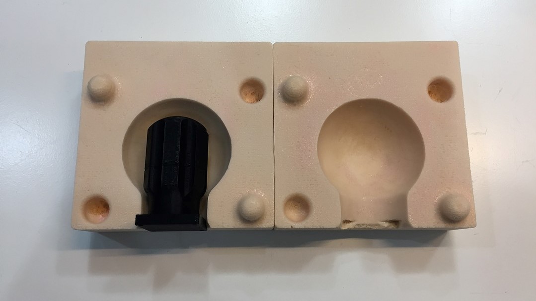
KNOB
This part of the casing has been the most complex, not because it is difficult, but because the process has been laborious. So that you understand the process more clearly, below you have a little 101 on how to make this piece:
- Design the part based on the pipette and the electronics that surround it.
- Create the mold that will allow the geometry to be generated.
- Export the file as .stl and prepare the milling with RhinoCAM.
- Once the milling is done, paint the inside of the mold with wood glue and sand (repeat 3 or more times)
- 3D print the core in PLA.
- Calculate the volume of silicone and mix it carefully. (mix 10-20% more just in case)
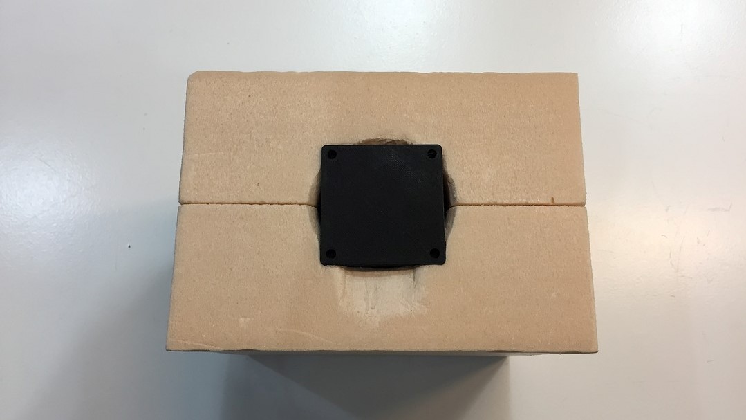
- Close the mold with tape and carefully pour the silicone.
- Let it dry according to the datasheet, open the mold and carefully cut the possible burrs.
Now I would like to show you some photos and videos of the process that I have just explained to you, I hope they give you a closer image of how everything has gone.
After milling the molds, the surface finish of the high-density polyurethane foam is not very good. That is why I did a painting process with wood glue and sanding (from 180 to 500 sandpaper weight). It was a heavy and hard process but it's worth it you'll see.
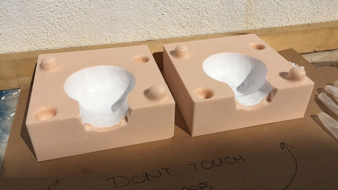
At this moment we are ready to close the mold properly, making sure that we do not have leaks and that everything is centered. Prepare the silicone mixture according to the specifications of the datasheet (part A 50% -partB 50% in volume) and fill the mold.
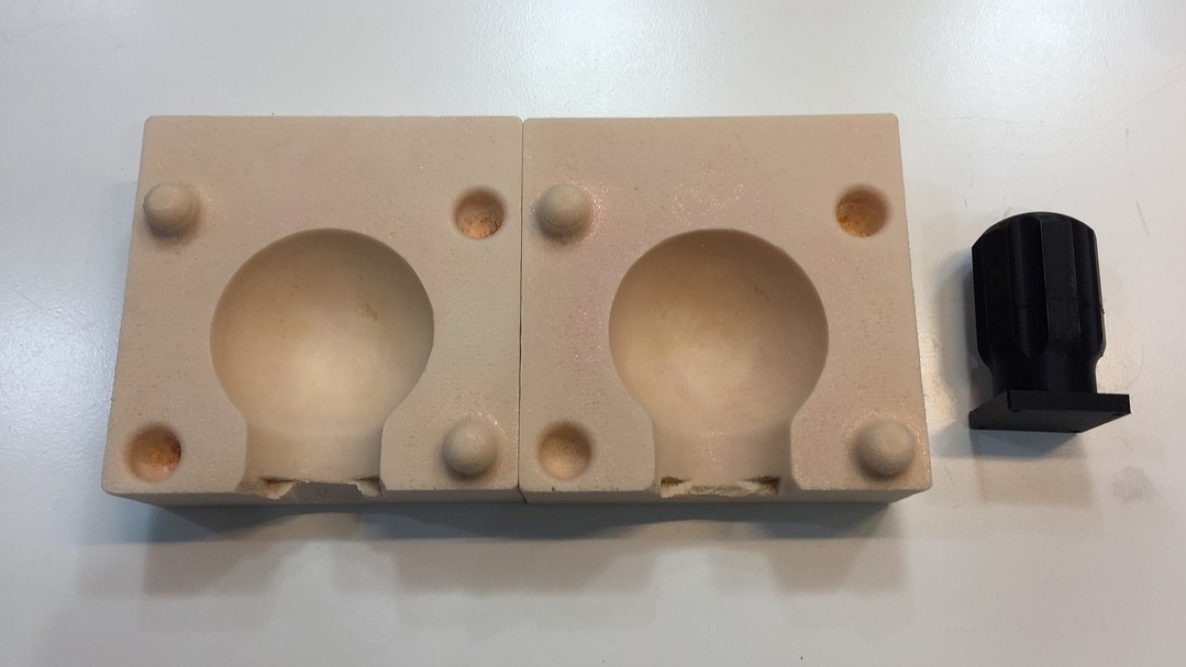
After the long process of preparing all the material to make the casting, I left the mold to rest overnight (the datasheet recommends 4-5 hours) to ensure that everything would be well cured and ready to mount.
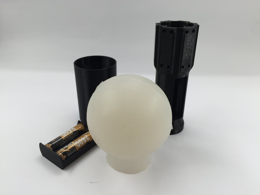
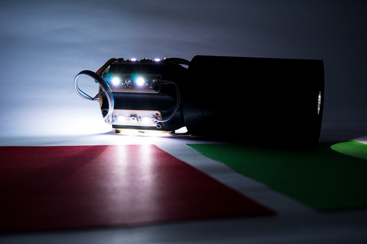
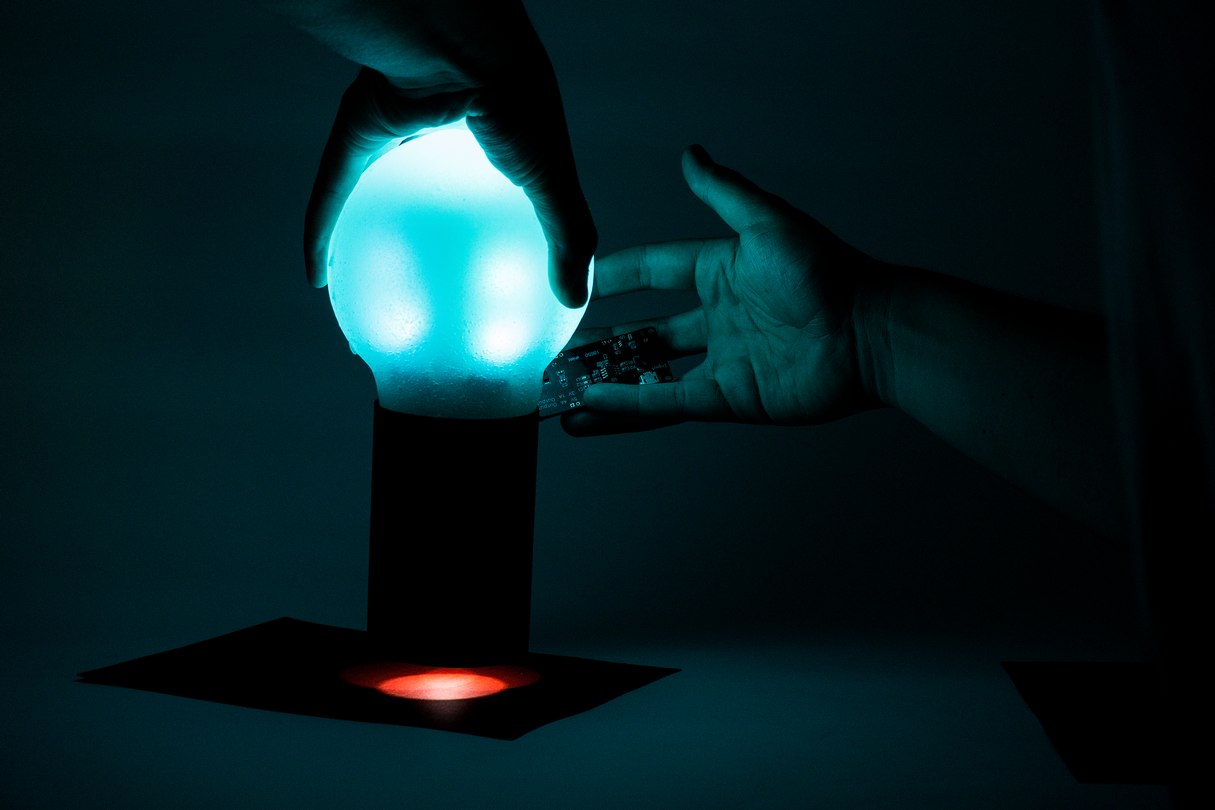
RESULTS
Here you have a series of images so that you can see other points of view of the final result of the manufacturing and the electronics already assembled.
And now some more elaborate photographs so that you can see the aspect in operation and in the dark.
SLIDE
VIDEO
BOM
Electronics
| Item | Vendor | Price |
|---|---|---|
| ATtiny1614 | Digikey | $0.80 |
| VEML6040A3OG | Digikey | $2.52 |
| Wireless Charger | BricoGeek | $18.90 |
| 2400 mAh li ion battery 18650 | BricoGeek | $11.92 |
| Adressable LED (10) | Digikey | $5.95 |
| $40.09 | ||
| 33.59€ | ||
Right now it is difficult to take into account absolutely all the components that will make up the electronics of the project, so for now I only refer to the key elements of the system. On the final project page you will find all the materials.
Fabrication
| Item | Vendor | Price |
|---|---|---|
| Brass Inserts | Amazon | $10.72 |
| Allen Bolts and Nuts | Amazon | $16.68 |
| PLA black | Amazon | $18.90 |
| Easyl 940-FDA | Feroca | $56.04 |
| HighDensity Poliuretane Foam | Amazon | $21.34 |
| $123.68 | ||
| 104.25€ | ||
LICENSE
- CC-BY-NC (Creative Commons Atributtion + NonCommercial + ShareAlike)
- CC-BY-ND (Creattive Commons Atributtion + Non Commercial + NoDerivates )


QUESTIONS
I believe that most of the questions have been answered in the body of this page, but some may need a more personal and concrete explanation. Here I highlight questions that I think may not have been clear.
What does it do?
This portable lamp reads colors from objects using a Vishay VEML6040 color sensor. It sends that information to an ATTiny1614 that converts that information into a digital signal. It sends the information to 18 neopixels scattered around the silicone screen and it lights up in the same color as the object it has read.
The user brings the bottom of the lamp closer to the object (where the sensor is located) and presses the screen as if it were a dropper. When it does that the reader reads the color and sends it to the LEDs. Whenever you want to change color you have to repeat that process.
What parts and systems were made?
The entire electrical system has been designed and manufactured by me, except for the welded components that have been purchased. At the manufacturing level, I can also say that everything has been manufactured and designed by me, except the hardware and the brass inserts that were purchased from the supplier. Finally, the interaction system between User and Product has also been designed from scratch.
What processes were used?
The processes used have been:
Electronics
- Electronics design
- Electronics production
- System integration
Code
- Programming
- Embedded Programming
Fabrication
- Computer-aided design
- 3D printing
- Hand soldering
- Computer controlled milling
- Hand sanding and mold finishing
- Molding and Casting
- 2D Design (storyboard)
What worked? What didn't?
I consider that almost everything I planned has worked correctly, but I would like to emphasize several things that either have not worked or that I have not had time to do to combine this FabAcademy with my work at the university.
- My original idea is that the entire lamp had a base that would function as a charging base and a light system. Communicating both and being able to save the color there. It has not been possible due to time and complexity but I do not rule out doing it in the future.
- While designing the system I did not think about placing a general on / off button. So right now the only way to turn it off is by manually disconnecting the power. I hope I can fix that with a little code that allows the user to turn on and off with a long press.
- The battery system inside the case has not been developed due to a lack of materials that did not arrive in time for the final presentation. I also hope to finish it in a few weeks or months.
- The color calibration is not very good, it usually works well with dark colors like red and blue, but it suffers with lighter ones. I think it is a code problem so I will try to solve it calmly.
ORIGINAL FILES
Link to Original files for my final project.