Computer-Controlled Cutting
HOW DOES COMPUTER-CONTROLLED CUTTING WORK?
This is the content we had covered this week:
W3 - Computer-Controlled Cutting
- Tools: knife, laser,laser, waterjet, hot wire, wire EDM.
- Lasercutter
- Vinyl Cutter
- CAD: Parametric.
- CAM:
Assignment
- Group assignment: characterize your lasercutter’s focus, power, speed, rate, kerf, joint clearance and types
- Individual assignment: cut something on the vinylcutter design, lasercut, and document a parametric construction kit, accounting for the lasercutter kerf which can be assembled in multiple ways, and for extra credit include elements that aren’t flat.
This week we’ve had the chance to try various digital fabrication tools in our Fablab. Here I’ll explain how the technology works and how we learned to use it.
LASER CUTTER
Laser Cutting can be relatively straightforward to do with basic training. However, to master it, certain steps should be followed to improve and get better results.
HOW THE LASER CUTTER WORKS
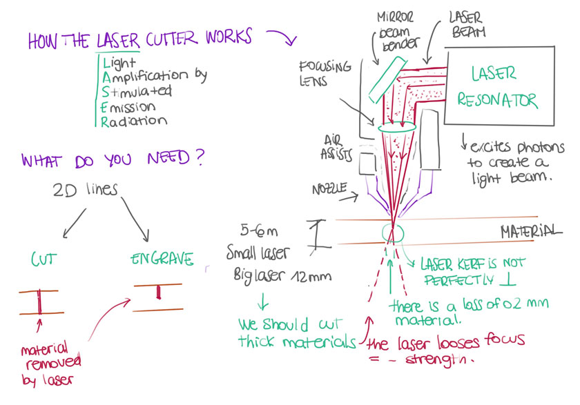
"Diagram showing how the Laser Cutter works"
HOW TO LASER CUT
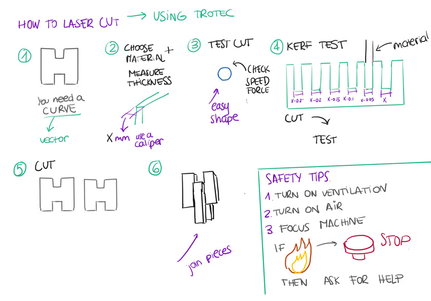
"Diagram showing how to Laser Cut from a 2D file to connecting two pieces together."
HOW TO GO FROM A 3D MODEL TO A LASER CUT READY FILE
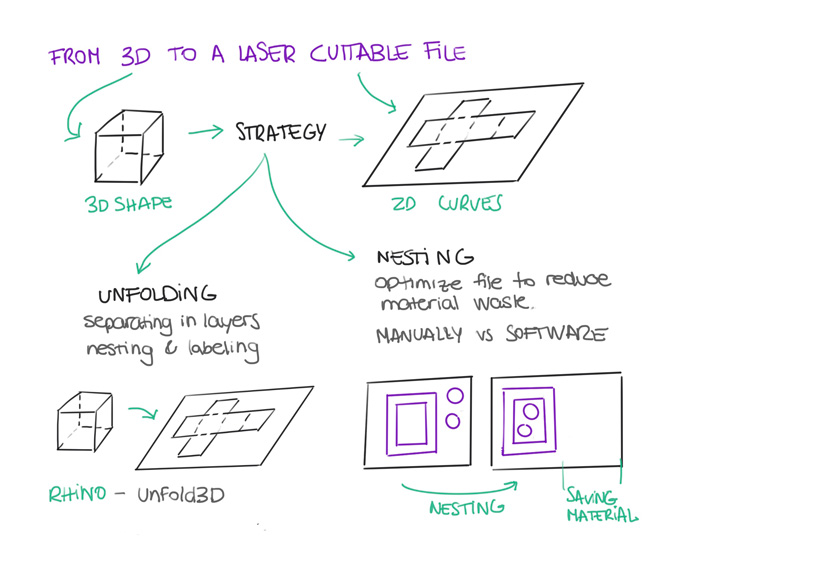
"Diagram showing how go from a 3D model to a 2D model ready to Laser Cut"
LASER CUTTER TRAINING | TROTEC
Trotec laser cutter is quite convenient to use. The setup in the lab uses Rhino + the proprietary Trotec interface to send the file to cut. So, to cut your file, you need a 2D curve that can be imported into Rhino. The traces need to be joined to make sure that there are no loose ends and double lines. Then you send it to Trotec and define the laser’s force and speed according to the material and thickness.
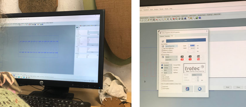
"Left: Creating a Kerf Test using Rhino. Right: Getting the file ready to cut with the Trotec Laser Cutter. Work with Den and Lynn."
Testing Laser Cutter with a Parametric Geometric Piece + Living hinge.
As part of the training, we cut a parametric piece with different slots and a living hinge piece. We worked in teams. As we did the kerf test before, we adjusted the slots’ width to ensure that the two pieces would fit.
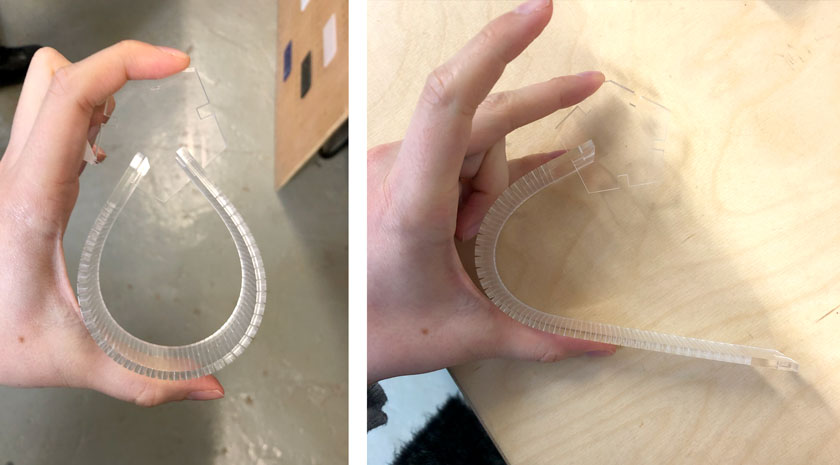
"Left: Fully folded living hinge attatched to the parmetric module (Adapted modelfrom Josep Martí). Right: Partially folded living hinge. Work with Den and Lynn. "
"Press fit + hinge on laser cut Acrylic"
WHAT WENT WELL
Outcomes: The training was super clear and straightforward.
Teamwork: Working together with other people was handy to achieve our goals.WHAT COULD BE BETTER
More control over CAD tools: I need to learn more CAD tooling to actually do exactly what I have in mind.
LASER CUTTER TRAINING | MULTICAM
We got the chance to try the Multicam. At first, it looks intimidating due to its large size and bulky buttons panel control. The process is not as different as with the Trotec but allows to cut thicker materials.
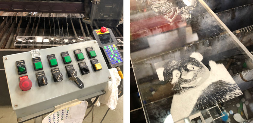
"Left: Multicam Laser Cutter interface. Right: Result of Engraving a Raster Image."
GROUP ASSIGNMENT
For the group assignment, we were asked to test different materials and produce different templates and kerf tests to experiment with different values and settings to get comfortable with the machine.
Class Material Templates + Kerf Tests
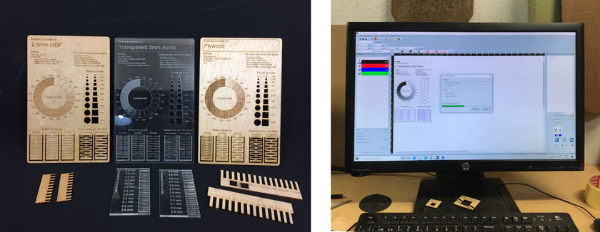
"Left: MDF, Acrylic + Plywood Material & Kerf Tests. Right: Sending Template to Cut. Special Thanks to Nil & Diego"
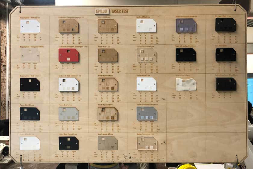
"Picture of the Laser Cutter Cheat Board with all the parameters."
MDF 2.5 mm
Cut: P 55 / S 0.5 / F 1000Hz | Engrave: P 70 / S 100 / F 1000Hz | Raster: P 80 / S 50 / F 1000 PPI
Transparent Acrilic 3 mm
Cut: P 60 / S 0.5 / F 20000Hz |
Engrave: P 70 / S 100 / F 20000Hz |
Raster: P 60 / S 100 / F 1000PPI
Plywood 4 mm
Cut: P 75 / S 0.5 / F 1000Hz | Engrave: P 65 / S 100 / F 1000Hz | Raster: P 60 / S 100 / F 1000PPI
WHAT WENT WELL
Valuable tooling: It showcases how useful these elements are.
Teamwork: The team worked very hard! I can’t thank them enough.WHAT COULD BE BETTER
I need to help more: I couldn’t be part of the assignment as much as I’d have wanted.
PARAMETRIC DESING | CAD
Parametric Design is a new thing to me in the formal sense. I’m very excited to get started with it as I expect to have plenty of modules in my final project. The parametric design will be essential to make sure that the modules work and fit at any scale.
FUSION 360 TRAINING
Modular Parametric Piece
During our training, we created a very similar piece to the one we laser cut. Here we can see all the parameters that we defined along the process.
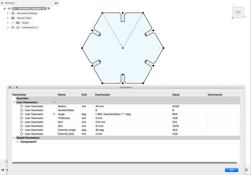
"Creating a Parametric piece with Fusion 360."
"Wooden Parametric piece made using Fusion 360."
WHAT WENT WELL
Reproducible: The workflow seemed very clear.
Adaptability: Nice parametric elements.WHAT COULD BE BETTER
Familiarity: More familiarity with the tool will ease the pace.
OPENSCAD TRAINING
Openscad training was clear step by step. Even though it doesn’t show as much flexibility as Fusion 360, the tools we used were easy to re-use.
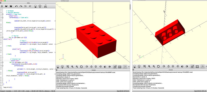
"Result of the OpenScad Training to Create a Lego Brick"
WHAT WENT WELL
Familiarity: I already knew a but the tool it was easy to follow
Fast results: It’s nice to create 3D models so fast! ( When knowing what you’re doing.)WHAT COULD BE BETTER
Very constraining: I personally find OpenScad to be very constraining. It could be a feature or a limitation, depending on what you want to do.
FINAL PROJECT
WEEKLY ASSIGNMENT | VINYL CUTTER
HOW TO VINYL CUT
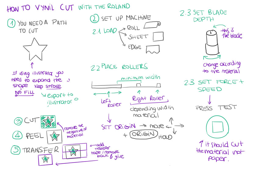
"Diagram showing how the use the Roland Vinyl cutter."
USING ROLAND VINYL CUTTER
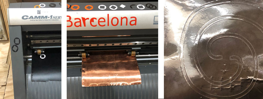
"Left: Testing Vinyl Machine, Center: Loading Copper Roll, Right: Spiral cut."
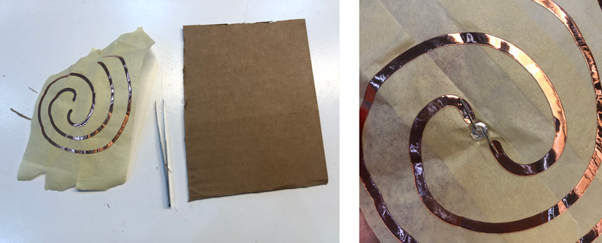
"Left: Transfer Tape with copper circuit + Tweezers + Cardboard , Right: Circuit + LED"
"Cutting Copper Foil with the Roland Vinyl cutter"
"Testing circuit with the power supply."
WHAT WENT WELL
Exploration: Enjoyed playing with Copper with the Vinyl Cutter.
Accuracy: It was very accurate cut. In this case, setting up the machine properly played a huge role!.WHAT COULD BE BETTER
Transfering: Transfering the copper requires a very precise plan to prevent wrinckles.
WEEKLY ASSIGNMENT | PARAMETRIC KIT
As part of my FabAcademy Journey I wanted to explore the digital fabrication tool of the week to convey a biological concept. In this case I’m working with the most basic unit of the genetic code: the ATCG letters.
My question was how could I use laser cutting to create parametric modules that would fit only on the possible letter combinations ( AT / CG)?
ATCG PARAMETRIC MODULAR STRUCTURE
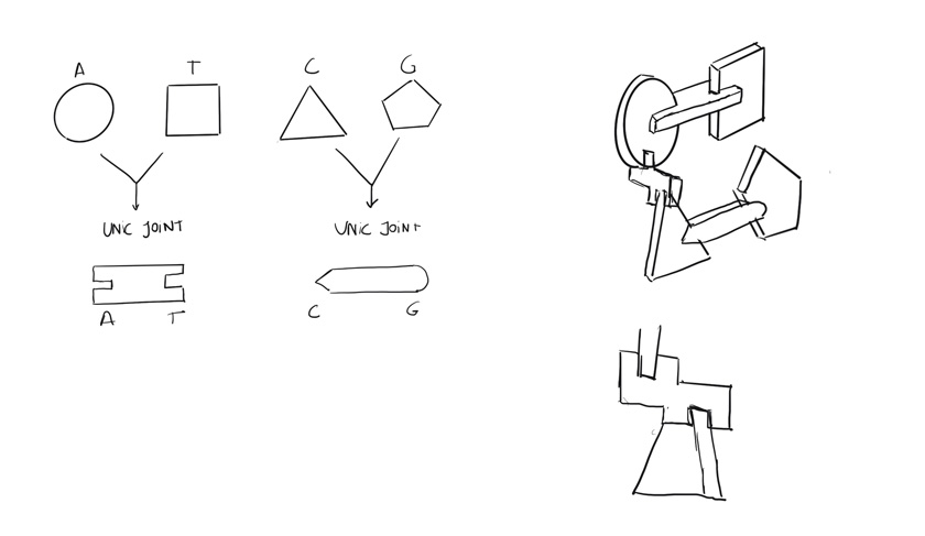
"How to create parametric modules from the "CODE OF LIFE" ATCG"
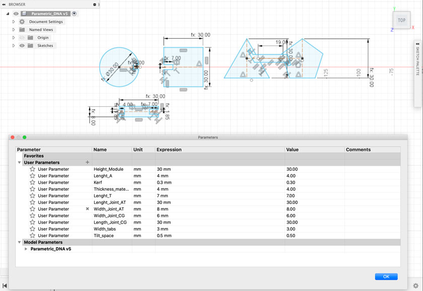
"Designing Parametric components for the DNA Kit."
My first attempt was using cardboard because I wanted a cheap and recyclable material to prototype. Cardboard is great, but not to work on such a small scale. The joints and the links broke almost immediately.
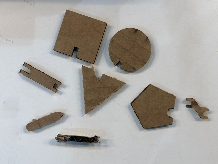
"Test Laser Cutting Carboard of the different Modules and connectors. A,T,C and G have different modules with different connectors. Some Pieces work better than others."
"Second iteration of the components for the DNA Kit."
"Iteration of the C G Module. "
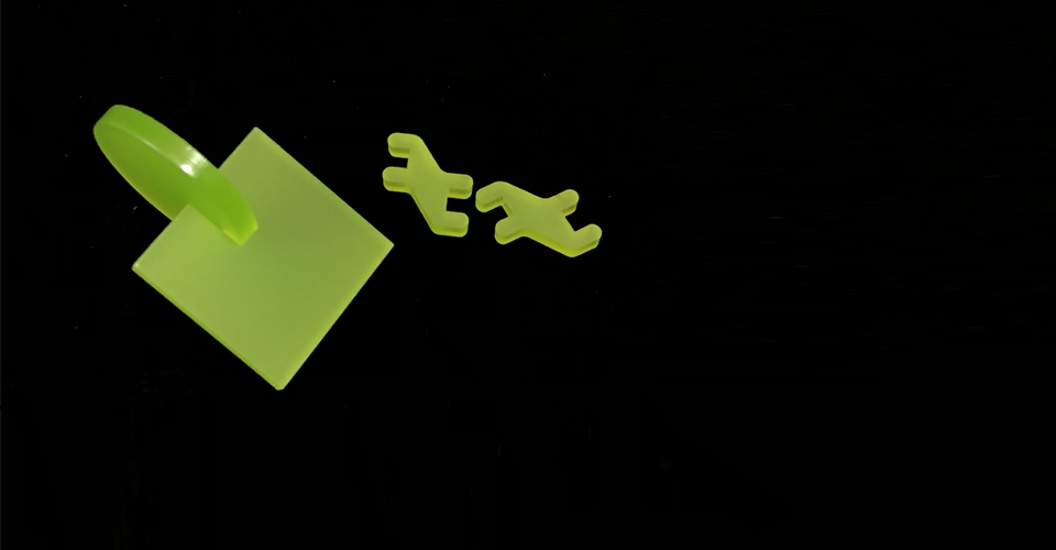
For this week’s final piece, I worked with acrylic that offered my stronger joints and a very playful and colorful material to play with.
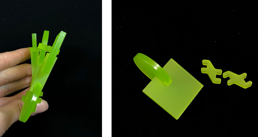
"Modular kit that includes unic pairs of pieces. In this case we can see A T stacking and creating the familiar spiral of the DNA"
"Left: Stacked modules from above where spiral movement can be seen , Right: Modules and connectors. "
WHAT WENT WELL
Kit works: Modules A & T work well.
WHAT COULD BE BETTER
Time management: I needed more time to try more ways to connect the different modules.
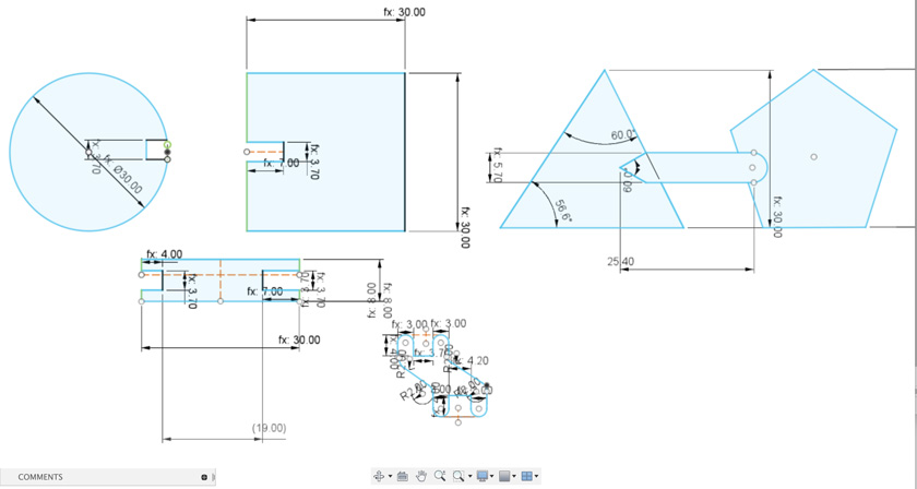
BONUS TRACK: FIXING THE CG MODULE + FINDING OTHER ISSUES
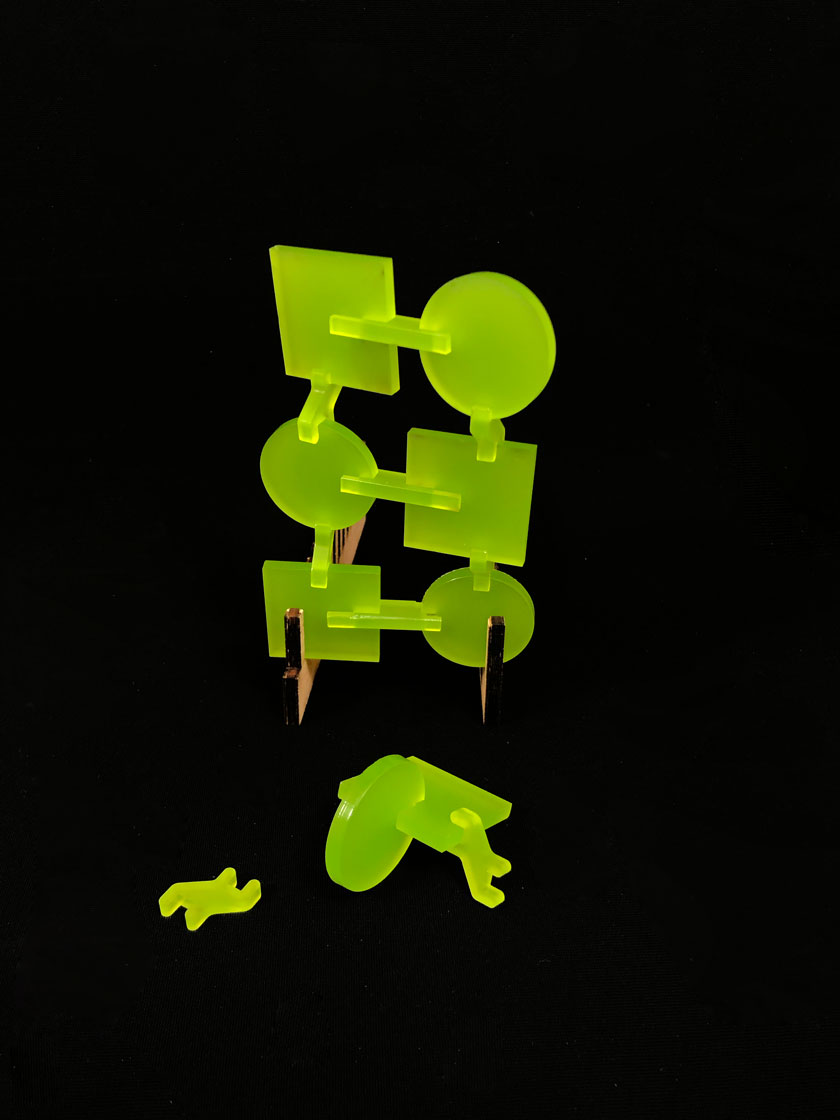
Some of the problems detected on the first iteration of the pieces was a design problem. I fixed the connection between the CG module with a new unique way to connect the two base pairs.
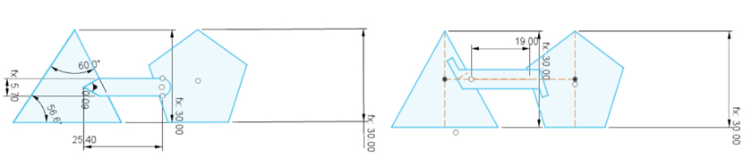
"Fusion 360 sketcht. LEFT: old design. RIGHT: new design"
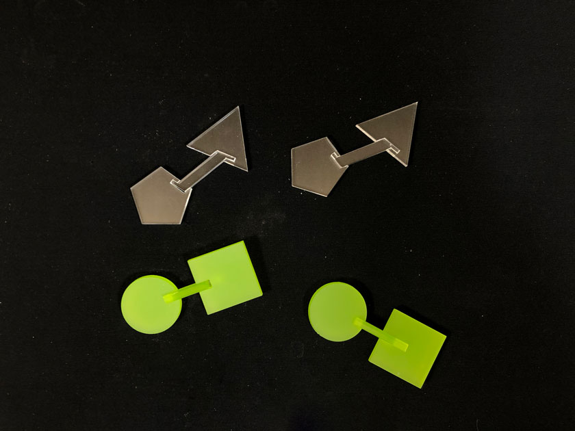
"Two pairs of AT modules & two pairs of CG modules. "
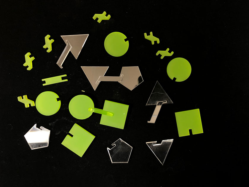
"Modular kit that includes all the elements to create the genetic code."
WHAT WENT WELL
Complete set:All elements needed to build the genetic code are designed.
WHAT COULD BE BETTER
Joints: There’s still room for improvement in terms of the pieces that allow stacking the pieces in a spiral shape.