11. Input devices
This week we tried several sensors. On this page you can see how a sensor works in practice.
Ultrasonic sensor
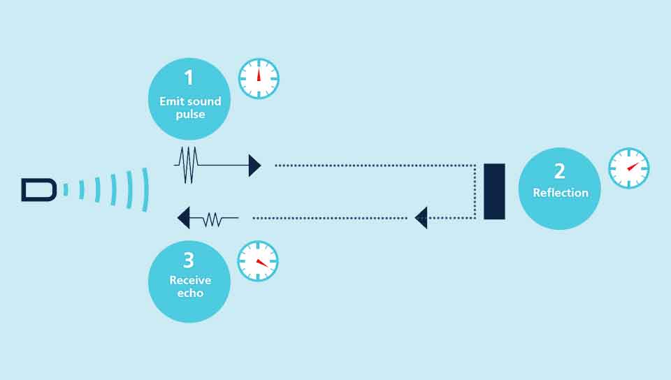
As the name suggests, the principle of operation is based on the use of ultrasound. These are acoustic waves whose frequency is too high to be heard by humans. An ultrasonic sensor emits short, high-frequency sound pulses at regular intervals. These pulses travel through the air at the speed of sound. When they hit an object, they are reflected back to the sensor as an echo. The sensor then calculates the distance to the target based on the time between the transmission of the signal and the reception of the echo.
 Credit : MicroSonic
Virtually all materials that reflect sound can be detected, regardless of their colour. Even transparent materials or thin sheets are no problem for an ultrasonic sensor.
Credit : Sparkfun
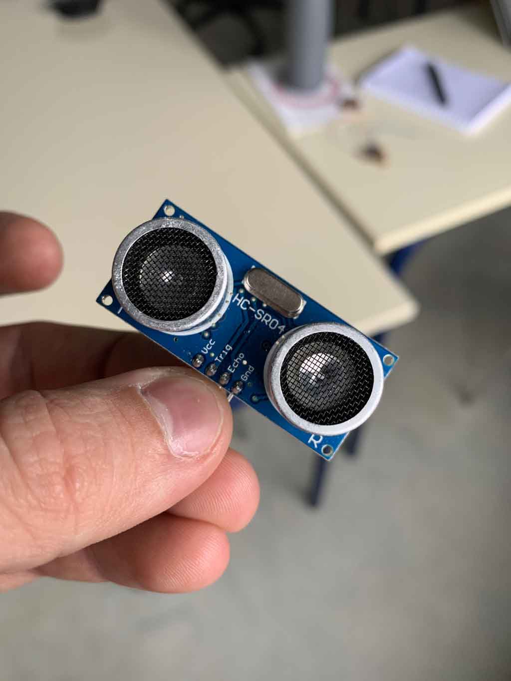
For the rest of the week I will be using a HC-SR04 sensor, which works with a 5 volt supply, has a measuring angle of approx. 15° and can measure distances between 2 centimetres and 4 metres with an accuracy of 3mm.
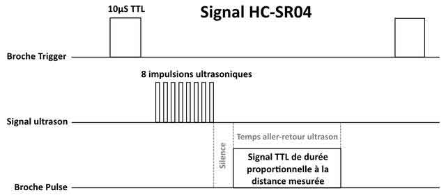
The principle of operation of the sensor is based entirely on the speed of sound. This is how a measurement is made:
- The sensor sends a 10µs HIGH pulse to the TRIGGER pin of the sensor.
- The sensor then sends a series of 8 ultrasonic pulses at 40KHz (inaudible to humans).
- The ultrasound travels through the air until it hits an obstacle and then returns in the other direction to the sensor.
- The sensor detects the echo and terminates the measurement. The signal on the ECHO pin of the sensor remains HIGH during steps 3 and 4, which allows the duration of the ultrasonic round trip to be measured and thus the distance to be determined.
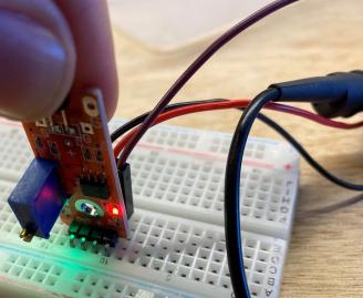
In order to preserve my microcontroller it is necessary to check its output voltage. The SAMD11C only accepts 3.3V so it is important to check the sensor’s output voltage especially since we are supplying it with 5V. For that I used the oscilloscope. Finally, after checking the output voltage of the sensor is almost 4V. After checking the SAMD11C datasheet, the microcontroller can accept up to 3.63V with a tolerance of 5%, which brings the limit to 3.8115V. It is therefore possible to put the sensor on the SAMD11C, however the microcontroller will wear out prematurely.
How does the sensor measure a distance?
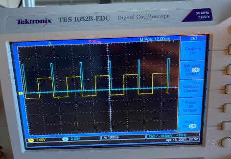
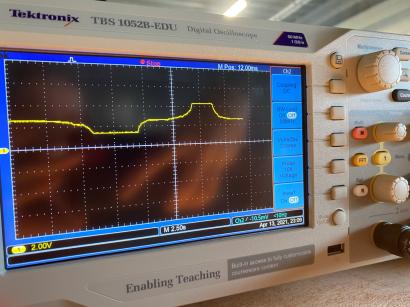
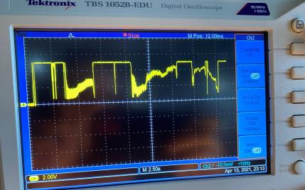
To understand in more detail how an ultrasonic sensor works I used an oscilloscope. With this tool, which allows us to see the signal, we can better understand the working principle of the sensor. As mentioned before, the sensor measures the distance according to the time it takes for the sound to travel back and forth. Let’s check how it works inside the circuit.
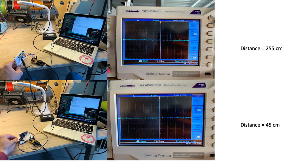
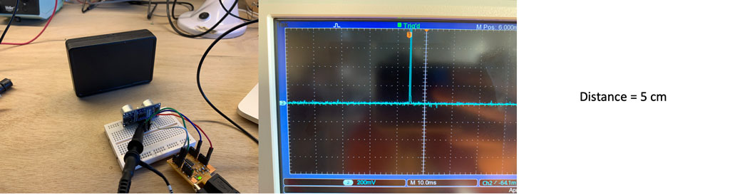
As you can see, the further away the object is, the longer the return time is. The microcontroller will therefore calculate the return time according to the speed of sound constant. This is how an ultrasonic sensor works.
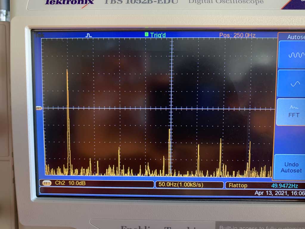
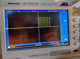
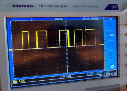
All these results were on the echo pad of the sensor but what happens on the trigger pad?
The trigger terminal is the element that sends the sound. When you connect this terminal to the oscilloscope you can see that it is sending out pulses. These pulses correspond to the time when the sonar emits the noise. We can therefore see that it emits a noise at regular time intervals which allows the echo terminal to receive the sound and calculate the time interval to deduce a distance
Joystick
To understand how a joystick is working, I use the oscilloscope. The joystick receive a 5V current, and send the value of the potential meter. It is a position sensor. I measured with the oscilloscope the value in X.
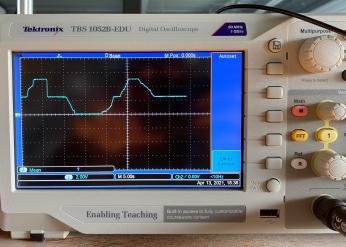
The middle position of the joystick output a middle current. I send a 5V and the joystick in the middle state send back around 2.5V. When I move the potential meter in one way or in another way, the signal goes up or down, depending on the position, to go to 0V from 5V.
Reed switch
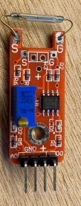
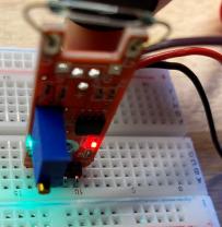
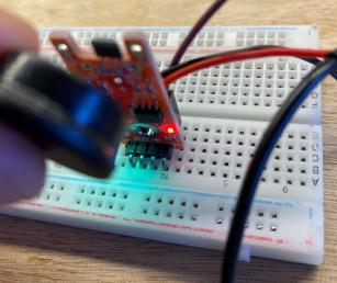
In the sensor kit for Arduino we have a reed switch. It is working with a magnet. There are two blades inside and when I approach the magnet the green light on the sensor turn on. The sensor is supplied in 5V.
When there is no magnet coming in send a signal of 5V, and when there is a magnet it comes to 0V. I reached to have a state in between depending on the distance of the magnet with the sensor.
Linear Hall
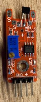
The linear hall sensor is working also with a magnet but it can read the side of the magnet. On the sensor there is a digital output or analog output.
First I measured with the analog and we can see a range of 2.5V for this sensor. If the magnet is on one side it send 1.25V and on the other side it send upper, 3.75V. The sensor send 2.5V without the magnet.
Then I plugged it with the digital output, and here it works with only one kind of sending signal, magnet (5V) or no magnet (0V).
Touch
I used also a touch sensor. I wired it both digital and analog.
The analog result was rather not precise. As we can see there is many variation on the output signal. When I don’t touch it is 0V, but when I touch it’s a lot of oscillation to reach 5V.
In digital output, the signal is more clear, touch is 5V, no touch is 0V.
Sonar
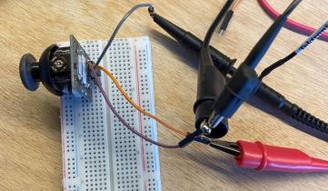
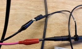
I finally want to see the probe with the sonar. Here is the wiring was little bit more complex.
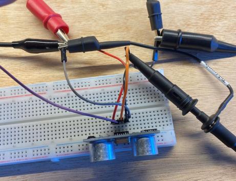
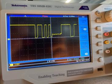
The sonar needs 5V to work. The trig pin is the output, it sends a signal to the sonar to send the ultrasound. The signal send to the sonar needs to be more than the half of 5V, 2.5V to trigger the ultrasound wave. That is why I used a signal sender with a squared signal at around 3V. It sends 6 pulse by minute.
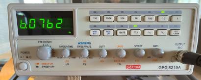
I measured it to be sure that it is not more than 5V to not spoil the sonar.
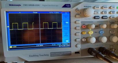
Then I plugged the other wire of the oscilloscope to the echo pin to see the signal received. On the oscilloscope, in yellow it is the signal send to the sonar, and in blue it is the signal received by it. The more the obstacle of the ultrasound wave is close, the more the thickness of the blue square will be small.