14. Networking and communications
Assignment
Individual assignment:
Design, build, and connect wired or wireless node(s) with network or bus addresses
Group assignment:
Send a message between two projects
Group assignment
Group:
● - Xinhui Hu
● - Zhengya Gong
● - Yazan Barhoush
● - Noora Nyberg
More details click Group assignment
Individual assignment:
At first, I did not get a better understanding in this weekly assignment, so I decided to simply use my Phone to control LED by Arduino UNO board and ESP8266. This assignment has referred to Arduino UNO & ESP8266 and control using smartphone.
After, I got the feedback from our instructors, I know I need to add the addressing system to control boards.
So, I referred to Jari’s weekly assignments.to control both of the boards, Arduino with LED and ATTiny 412 that I made in the weekly 6.
The core mechanism of this type of serial connection is to let the devices share the Tx and Rx input.
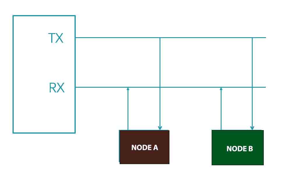
Node 1.Arduino Uno board
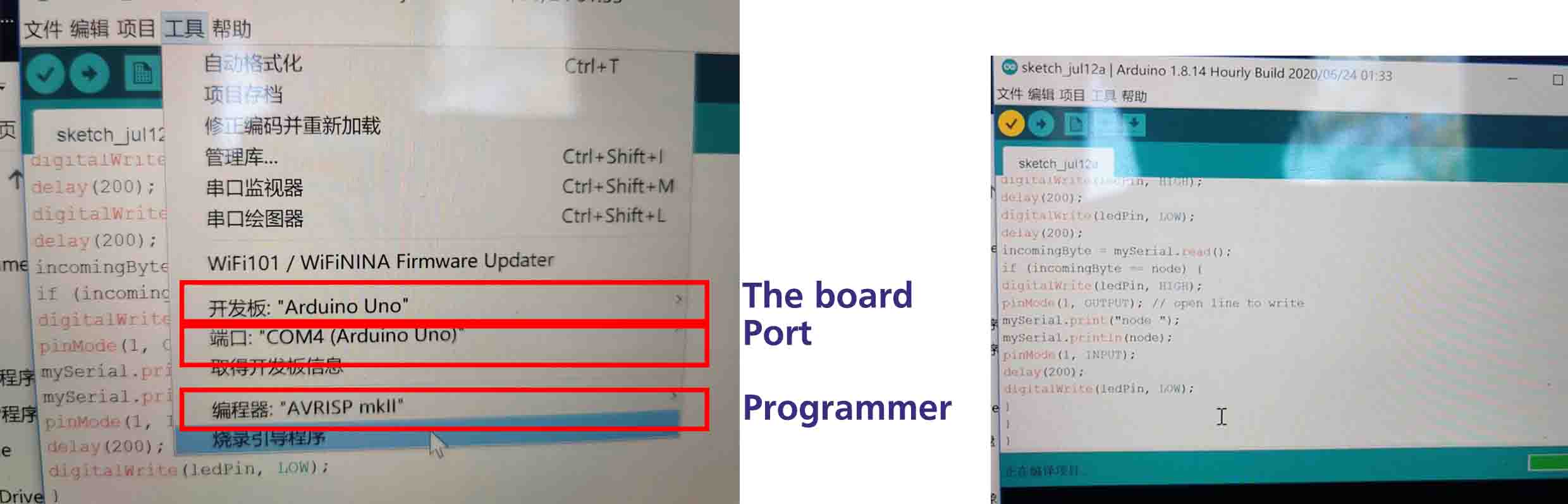
● Programming the Arduino UNO board. I tried many times, also modified the code according to other suggestions. Moreover, downloaded Arduino software again and tried. However, it shown, not found the SoftwareSerial.h. Then, I think maybe because of the Mac system, I restarted my laptop in Windows and tried again. It is worked.
Upload
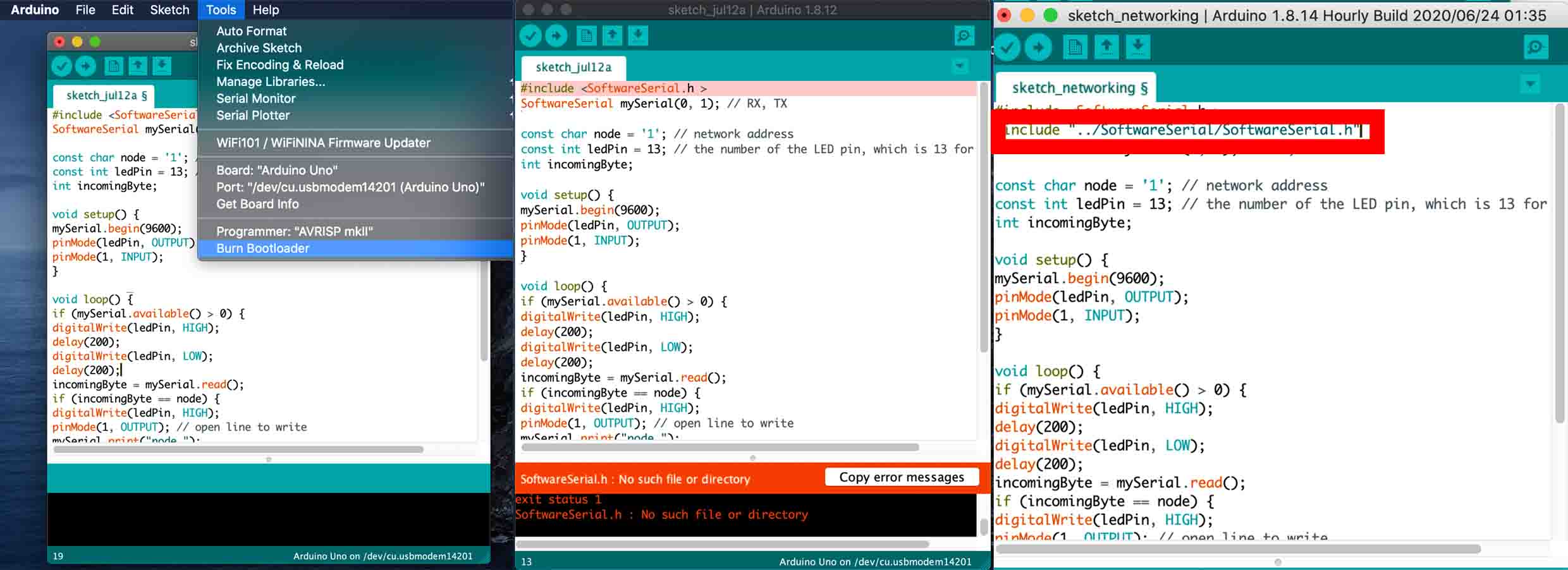
The code are shown as below, which referred to Jari’s archive.
#include <SoftwareSerial.h >
SoftwareSerial mySerial(0, 1); // RX, TX

const char node = '1'; // network address
const int ledPin = 13; // the number of the LED pin, which is 13 for UNO board
int incomingByte;

void setup() {
mySerial.begin(9600);
pinMode(ledPin, OUTPUT);
pinMode(1, INPUT);
}

void loop() {
if (mySerial.available() > 0) {
digitalWrite(ledPin, HIGH);
delay(200);
digitalWrite(ledPin, LOW);
delay(200);
incomingByte = mySerial.read();
if (incomingByte == node) {
digitalWrite(ledPin, HIGH);
pinMode(1, OUTPUT); // open line to write
mySerial.print("node ");
mySerial.println(node);
pinMode(1, INPUT);
delay(200);
digitalWrite(ledPin, LOW);
}
}
}
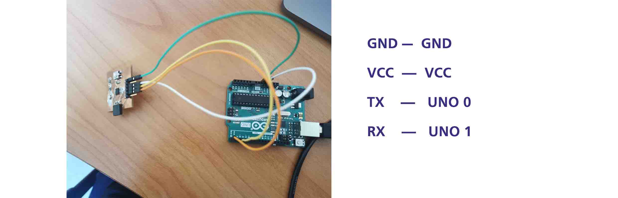
Node 2. ATTiny 412
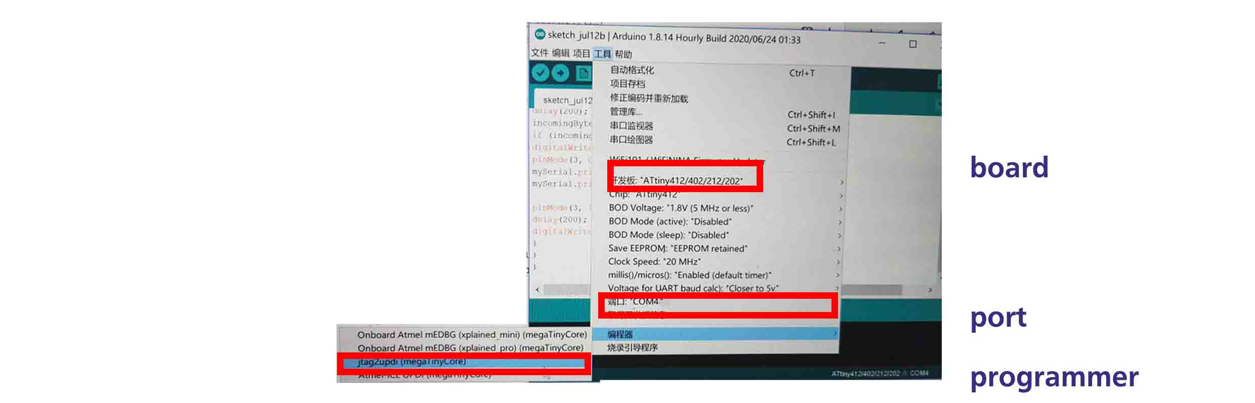
● Programming the ATTiny 412.
How to connect the ATTiny 412 and Arduino board. I checked the 6 weekly assignment, and point out the TX, RX, GND and VCC, also Achille Gakwaya told me how to connect the boards yesterday.
● GND: ATTiny412 Pin 8 - Board Pin 1 -UNO GND
● VCC: ATTiny412 Pin 0 - Board Pin 3 - UNO 5V
● TX : ATTiny412 Pin 3 - Board Pin 4 - UNO 1(TX)
● RX : ATTiny412 Pin 4 - Board Pin 5 - UNO 0 (RX)
Code
Based on the code1, I modified the code2. The main different shown bellow.
SoftwareSerial mySerial(3,2); // RX,TX
const char node =‘2’;
const int ledPin = 1; // the number of the LED pin
Including SoftwareSerial library and setting up pins for RX and TX and network addresses for the nodes.
#include <SoftwareSerial.h>
SoftwareSerial mySerial(2,3); // RX, TX (The ATTiny Pin number, NOT the board Pin number)

const char node = '2'; // network address
const int ledPin = 1; // the number of the LED pin

int incomingByte;
void setup() {
mySerial.begin(9600);
pinMode(ledPin, OUTPUT);
pinMode(3, INPUT);
}

void loop() {
if (mySerial.available() > 0) {
digitalWrite(ledPin, HIGH);
delay(200);
digitalWrite(ledPin, LOW);
delay(200);
incomingByte = mySerial.read();
if (incomingByte == node) {
digitalWrite(ledPin, HIGH);
pinMode(3, OUTPUT); // open line to write
mySerial.print("node ");
mySerial.println(node);

pinMode(3, INPUT);
delay(200);
digitalWrite(ledPin, LOW);
}
}
}
Upload
I used the Arduino IDE Serial Monitor which can be evoked by clicking the icon the right-top corner to test it.
When I typed the node number, it has shown the node name, and the LED on the board responded.
Also, I designed the final project with wireless connection. More detail click.