11. Output Devices
Assignment
Individual assignment:
● Add an output device to a microcontroller board you’ve designed, and program it to do something
Group assignment:
● Measure the power consumption of an output device
Group assignment
Group:
● - Xinhui Hu
● - Zhengya Gong
● - Yazan Barhoush
● - Noora Nyberg
More details click Group assignment
Individual assignment:
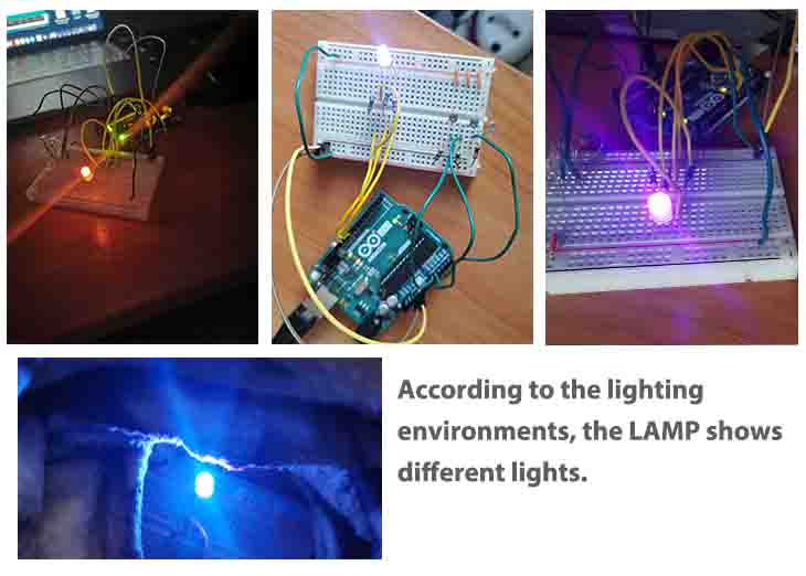
This week I used a tri-color Led and three photoresistors and created a lamp that smoothly changes colors according to lighting conditions.
Because of the virus, the fab lab closed two weeks ago; everyone stays home working remotely, so I need to design something independently. It is not easy for me to add a sensor to a microcontroller board, but fortunately, Ari sent me Arduino Projects Book, which helps me follow the book to design the lamp.
● Step 1. Find out the components. Maybe it is easy for individuals who are familiar with electronics; however, for me, I even can not identify the different resistors. Therefore, I googled the keywords, and watch some video.
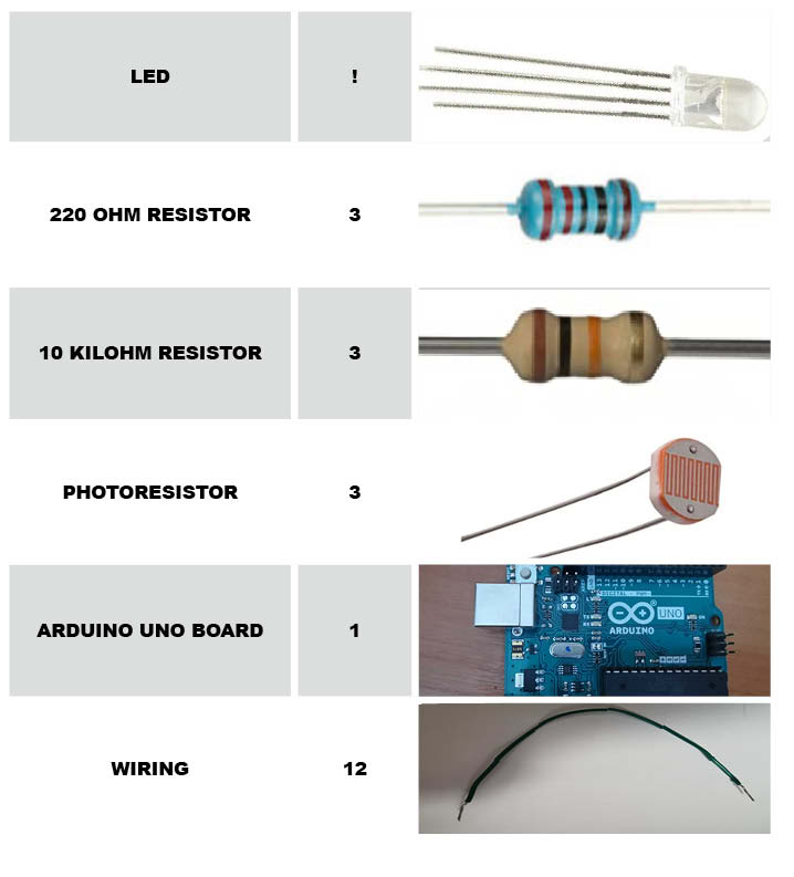
Figure 1. The components
● Step 2. Build the circuit.
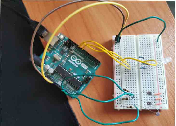
Figure 2. The circuit
● Step 3. Connect to my laptop. I used the USB cable to connect the Arduino board to my laptop. I opened the Arduino IDE and set all settings as shown in the tool.
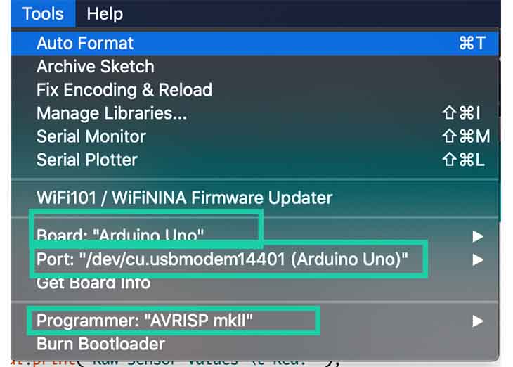
Figure 3. The tool setting
● Step 4. Programming.
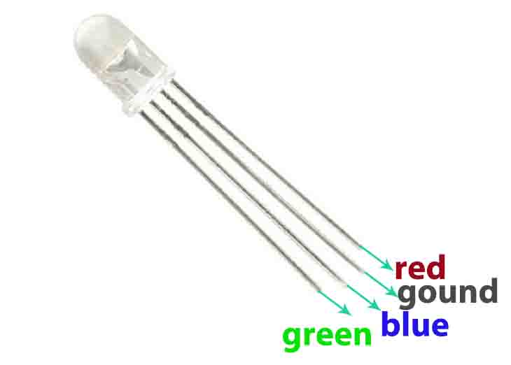
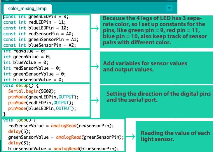
Because the 4 legs of LED has 3 separate color, so I set up constants for the pins, like green pin = 9, red pin = 11, blue pin = 10, also keep track of sensor pairs with different color.
Code Example
const int greenLEDPin = 9;
const int redLEDPin = 11;
const int blueLEDPin = 10;
const int redSensorPin = A0;
const int greenSensorPin = A1;
const int blueSensorPin = A2;
int redValue = 0;
int greenValue = 0;
int blueValue = 0;
int redSensorValue = 0;
int greenSensorValue = 0;
int blueSensorValue = 0;
void setup() {
  Serial.begin(9600);
  pinMode(greenLEDPin,OUTPUT);
  pinMode(redLEDPin,OUTPUT);
  pinMode(blueLEDPin,OUTPUT);
}
void loop() {
  redSensorValue = analogRead(redSensorPin);
  delay(5);
  greenSensorValue = analogRead(greenSensorPin);
  delay(5);
  blueSensorValue = analogRead(blueSensorPin);
  Serial.print("Raw Sensor Values \t Red: ");
  Serial.print(redSensorValue);
  Serial.print("\t Green: ");
  Serial.print(greenSensorValue);
  Serial.print("\t Blue: ");
  Serial.print(blueSensorValue);
  redValue = redSensorValue/4;
  greenValue = greenSensorValue/4;
  blueValue = blueSensorValue/4;
  Serial.print("Mapped Sensor Values \t Red: ");
  Serial.print(redValue);
  Serial.print("\t Green: ");
  Serial.print(greenValue);
  Serial.print("\t Blue: ");
  Serial.print(blueValue);
  analogWrite(redLEDPin, redValue);
  analogWrite(greenLEDPin, greenValue);
  analogWrite(blueLEDPin, blueValue);
}
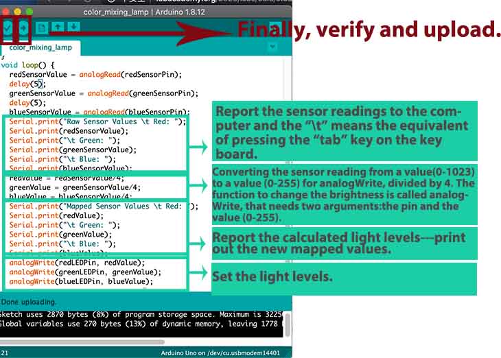
The function to change the LED’s brightness via PWM is called analogWrite(). It needs two arguments: the pin to write to, and a value between 0 - 255. This second number represents the duty cycle the Arduino will output on the specified pin. A value of 255 will set the pin HIGH all the time, making the attached LED as bright as it can be. A value of 127 will set the pin HIGH half the time of the period, making the LED dimmer. 0 would set the pin LOW all the time, turning the LED off. To convert the sensor reading from a value between 0 - 1023 to a value between 0 - 255 for analogWrite(), divide the sensor reading by 4.
● Step 5. Testing.
Individual assignment 2(for final project):
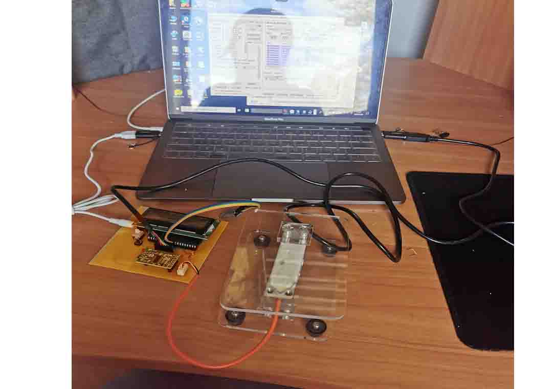
For my final project, in input device week I created a circle (integrated with input, output device and networking and communication)and designed my PCB board. So for this week, I tested my board and did programming. Also, the networking and communication in networking and communication.
It is a challenge for me. I used the Keil (download link)to write the code and STC-ISP (download link to program. The reason because the Keil is easy for new one to program, and many people recommended to use it. The another reason because I found various codes related to my project online. I downloaded the codes and edited it.
write the code
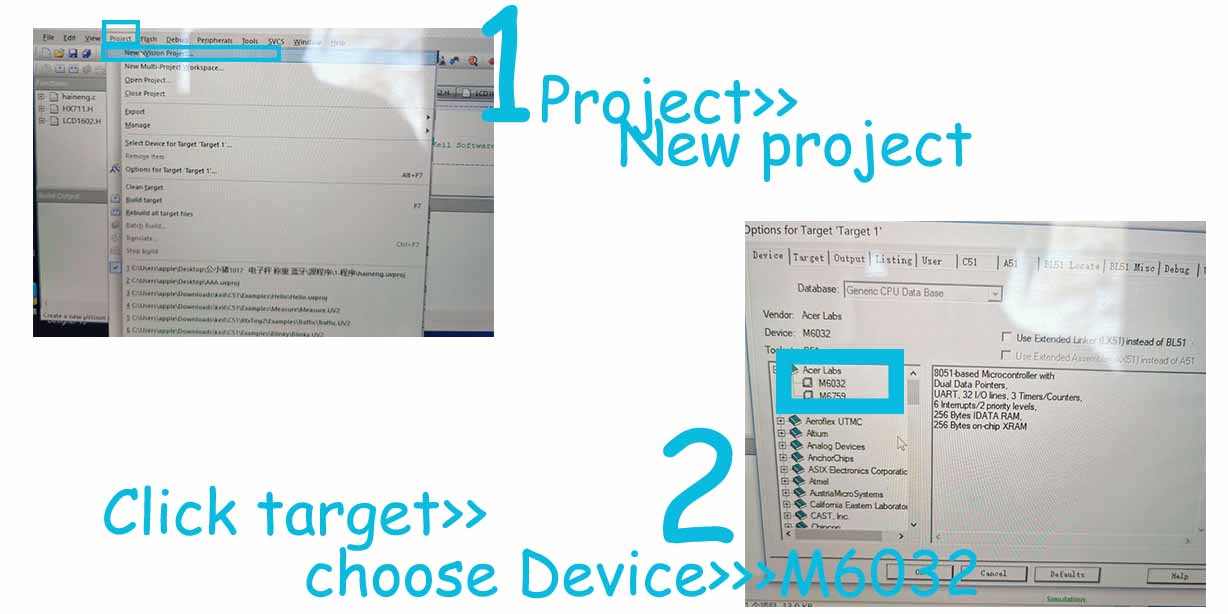
● 1. Download the Keil (download link), and create a new project.
● 2. Choose the target, then click the device to choose M6032.
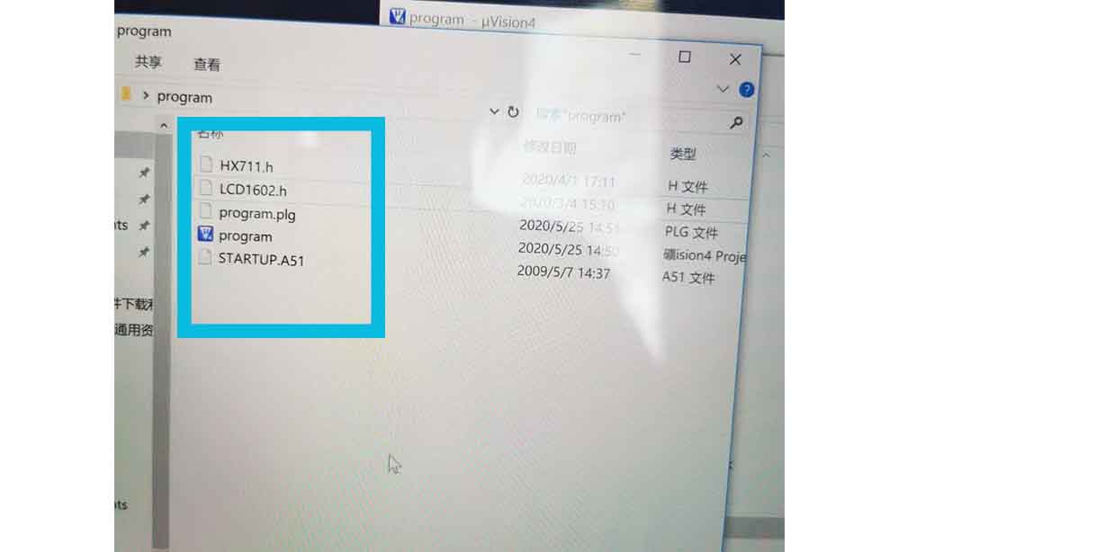
● 3. Store the project in a folder, it will automatically create another files, named .plg and startedup.A51 and added the HXL711.h and LEC1602.h. in the folder.
● 4.Write program in C using Keil.
I just copied some code from open source1, and according my project to edit it.
To control the weight sensor using HX711, code from some forums.
#ifndef __HX711_H__
#define __HX711_H__

#include <intrins.h>
#include <string.h>


unsigned long HX711_Buffer = 0;
unsigned long Weight_Maopi = 50;
 unsigned long Weight_Maopi_0 = 0;
 unsigned long Weight_Shiji = 0;
 unsigned long  Weight_Shiwu = 0;

#define GapValue 379

//=================================//IO set

sbit HX711_DOUT=P1^2;
sbit HX711_SCK=P1^3;

//Function or variable declarations
extern void Delay__hx711_us(void);
extern unsigned long HX711_Read(void);


//****************************************************
//The time delay function
//****************************************************
void Delay__hx711_us(void)
{
    _nop_();
    _nop_();
}

//****************************************************
//Read HX711
//****************************************************
unsigned long HX711_Read(void)
{
    unsigned long count;
    unsigned char i;
    HX711_DOUT=1;
    Delay__hx711_us();
    HX711_SCK=0;
    count=0;
    while(HX711_DOUT);
    for(i=0;i<24;i++)
    {
        HX711_SCK=1;
        count=count<<1;
        HX711_SCK=0;
        if(HX711_DOUT)
            count++;
    }
    HX711_SCK=1;
    count=count^0x800000;//When the 25th pulse comes down the edge, convert the data
    Delay__hx711_us();
    HX711_SCK=0;
    return(count);
}


//****************************************************
//MS delay function (test under 12M crystal vibration)
//****************************************************
void Delay_ms(unsigned int n)
{
    unsigned int  i,j;
    for(i=0;i<n;i++)
        for(j=0;j<123;j++);
}


//****************************************************
//Measuring weight
//****************************************************
uint jilu;
uint zhongliangcha;
void Get_Weight()
{
    static  bit maopi=1;
    Weight_Maopi_0  = HX711_Read()/GapValue;
    Weight_Maopi_0 = Weight_Maopi_0%10000;

    if(maopi)
    {


                if(Weight_Maopi_0==Weight_Maopi)
                maopi=0;
                Delay_ms(200);
                Weight_Maopi = Weight_Maopi_0  ;
    }else
    {
        Weight_Shiji = Weight_Maopi_0 - Weight_Maopi;       //get net weight
//              Weight_Shiwu = Weight_Shiji; //ce shi yong
        if(Weight_Shiji>5&&Weight_Shiji<90000 )
        {


                if(Weight_Shiji%10==0)
                {
                        Weight_Shiwu =  Weight_Shiji  ;
                }
                else
To control the LCD1602 Screen, the code from
#ifndef _LCD1602_H_
#define _LCD1602_H_

#define uchar unsigned char
#define uint unsigned int

#define LCD1602_dat P0  //Data parallel port macro definition


sbit LCD1602_rs=P2^5;//IO definition
sbit LCD1602_rw=P2^6;
sbit LCD1602_e=P2^7;


void LCD1602_delay(uint T) //The time delay function
{
    while(T--);
}

/********************************************************************
* name: LCD1602_write(uchar order,dat)
* function: 1602 write as data function
* input: order is the data/command switch variable //0 is the command 1 is the data
* : dat is the data/command sending data
* output: none
***********************************************************************/
void LCD1602_write(uchar order,dat)  //1602 One byte processing
{
    LCD1602_e=0;
    LCD1602_rs=order;
    LCD1602_dat=dat;
    LCD1602_rw=0;
    LCD1602_e=1;
    LCD1602_delay(1);
    LCD1602_e=0;
}
/********************************************************************
* name: LCD1602_writebye(uchar *prointer)
* function: 1602 write data function pointer
* input: enter what needs to be displayed
* output: none
***********************************************************************/
void LCD1602_writebyte(uchar *prointer)  //1602 String processing
{
    while(*prointer!='\0')
    {
        LCD1602_write(1,*prointer);
        prointer++;
    }
}
/********************************************************************
* name: LCD1602_cls()
* function: initialize 1602 liquid crystal
* input: none
* output: none
***********************************************************************/
void LCD1602_cls() //1602 initialization
{
    LCD1602_write(0,0x01);     //1602 clearing instructions
    LCD1602_delay(1500);
    LCD1602_write(0,0x38);     // Function Settings: 8-bit, 5*7 lattice
    LCD1602_delay(1500);
    LCD1602_write(0,0x0c);     //Set the cursor not to show the switch, not to show the cursor, the character does not flicker
    LCD1602_write(0,0x06);
    LCD1602_write(0,0xd0);
    LCD1602_delay(1500);
}
● 4. Write the codes, that included the HXL711.h and LEC1602.h.
Actually, I downloaded the codes online and edited, the main different is following.

#include <reg52.h>
#include"LCD1602.h"   //LCD1602 display
#include"HX711.h"//read weight
#define uchar unsigned char
#define uint unsigned int
  //---------------------------------->T0
bit read_Weight=0;//Read the weight marker bit
sbit Led=P1^1;
sbit beep=P2^0;
//----------------------------------->Function declaration
 void display();//display function
 void T0init();//T0 initialization
 void AnJian();// key
void uart_zijie(uchar zijie);
 void uart_zifu(uchar *zifu);
//********Main function *****************************
void main()
{
    T0init();//T0 initialization
    LCD1602_cls(); //LCD1602 initialization
//==========major cycle==============================
    while(1)
    {
        display();
        if(read_Weight)
        {
            read_Weight=0;
            Get_Weight();      //As the variable Weight_Shiwu is generally 10 kilograms, an overweight alarm should be added        }
            uart_zifu("Data,");
            if(Weight_Shiwu>999)uart_zijie('0'+Weight_Shiwu/1000%10);
            if(Weight_Shiwu>99)uart_zijie('0'+Weight_Shiwu/100%10);
            if(Weight_Shiwu>9)uart_zijie('0'+Weight_Shiwu/10%10);
            uart_zijie('0'+Weight_Shiwu%10);
            uart_zifu(",");
            if(Led)  uart_zijie('1');
            else     uart_zijie('0');
            uart_zifu(",\r\n");
    }
}
 //========T0 initialization==========================
void T0init()//T0 initialization
{
    TMOD=0x01;
    TL0 = 0x00;     //Set the initial timing value of 50ms
    TH0 = 0x4C;     //Set the timing initial value
    ET0=1;
    TR0=1;
    EA=1;
    SCON = 0X50;
    T2CON = 0X34;
    RCAP2H = 0XFF;
    RCAP2L = 0XDC;
 }
 //-=======================================
void uart_zijie(uchar zijie)
{
      SBUF = zijie;
      while(!TI);
      TI=0;
}
void uart_zifu(uchar *zifu)
{
    while(*zifu)
    {
        uart_zijie(*zifu++);
    }
}
uchar sec=0;
 bit shanshuo=1;
//======Display  function==============================
void display()//Display  function
{


        //The first line shows the weight data with the Settings of the overweight bar
        LCD1602_write(0,0x80);
        LCD1602_writebyte("      Hello    ");
        LCD1602_write(0,0xC0);
        LCD1602_writebyte(" Weight:");
        if(Weight_Shiwu<10000)
        {
                if(Weight_Shiwu>999)LCD1602_write(1,0x30+Weight_Shiwu/1000%10);
                else                LCD1602_write(1,' ')    ;
                if(Weight_Shiwu>99)LCD1602_write(1,0x30+Weight_Shiwu/100%10);
                else                LCD1602_write(1,' ')   ;
                if(Weight_Shiwu>9)LCD1602_write(1,0x30+Weight_Shiwu/10%10);
                else                LCD1602_write(1,' ')  ;
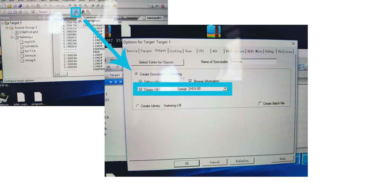
● 5. Automatically create a hex file for programming. Click the target, and create HEX file.
programming
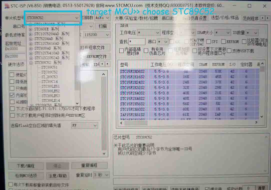
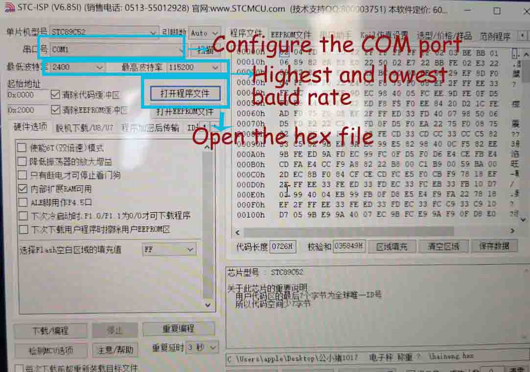
I used STC-ISP (download link to program.
● 1. I downloaded a later version from stcmcu.com and installed it.
● 2.Start the STC-ISP software(double click STC-ISP) Select the target MCU>> choose STC89C52.
● 3. Connect the board to my laptop.
● 4. Open the hex file, Configure the COM port, and set up the Highest baud rate and lowest baud rate.
● 5. Press download and programming.
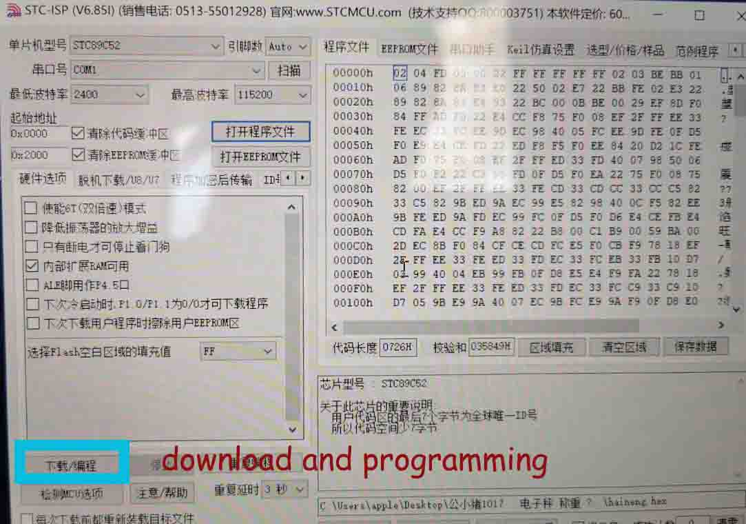
● 6. Switch on the power on my board. (That is important, although I do not know the reason, everyone mentioned that, before pressing the download, the power switch should turn off. )
After....
Finally.....my board is working, when I pressed the power switch, it measured the weight, the LCD shown the measured weight is 0g, and beep few seconds. When I put something on the surface, it measured the weight again. Because the item weight is more than setting(100g), it would not beep, just shown the weight.