18. Mechanical Design and Machines week
This week’s assignment:
Mechanical Design (part 1 of 2)
Group assignment

Design a machine that includes mechanism + actuation + automation
Build the mechanical parts and operate it manually.
Document the group project
Individual assignment:

Document your individual contribution.
Machine Design (part 2 of 2)
Group assignment

Actuate and automate your machine.
Document the group project
Individual assignment:

Document your individual contribution.
This week’s assignment is a little different from other weeks. It is a group project, where we will have to build, actuate, automate our own machine. We started this week by working to plan everything out, then split into smaller teams of two in order to divide the workload.
Brainstorming Ideas
The group began by looking at past projects that people made for this week. Some ideas we were interested in including: - a time-lapse dolly
We decided that we liked the concept of a pancake maker, but wanted to alter it to be a cupcake pan filler. The machine we would make would fill a cupcake pan with the correct amount of cupcake batter.
Materials
-
Cupcake pan: 15.25”x10.8125” (width x length)
-
Cupcake hole diameter: 2.875”
-
Distance between two holes: 0.46875
-
Distance between the centers of two holes: 3.34375”
-
volume for individual cupcake hole: 95 mL
-
Pulley and belting
-
12mm linear rail
-
Driver shield/ stepper motors (grbl boards)
-
End supports: to be laser cut with acrylic + 3D printed components
-
x2 Stepper motors (gantry)
-
X1 servo motor (release mechanism)
Components
A bag with the mix and a mechanism to “release” the cupcake batter from the bag Two-axis movement machine that goes over the cupcake tray We decided to use a different project that we had been considering as the inspiration for the two-axis movement component The pancake maker used the same two-axis movement component, but this project displayed it better.
We all worked for a while on designing the gantry system and the Release mechanism. We used inspiration from a fab inventory management system, another gantry, and the sites listed in our brainstorming ideas.
We also used this fellow [Charlotte Latin student’s idea for a dispenser]https://sites.google.com/charlottelatin.net/julian-evans-digital-portfolio/engineering-1/engineering-1/final-project?read_current=1 and this instructable user’s ideas for the release mechanism. Instead of 3d printing a batter holder (our original idea) we bought one from Amazon.. We decided that none of us want to eat cupcake batter that has been sitting in PLA. We used the sites listed above to automate the release of the batter.
This is the original sketch the full class came up with, sketched by Elaine Liu.
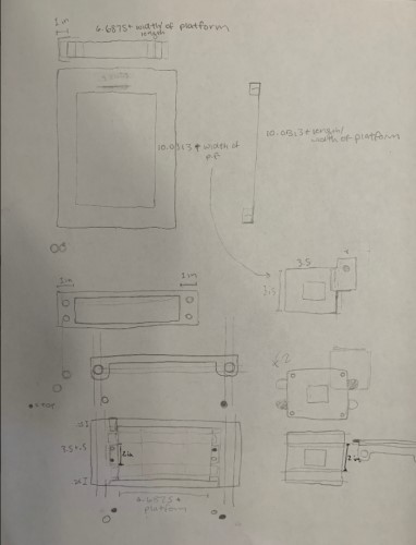
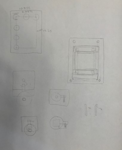
We then split into smaller groups of 2-3 to split up the workload. One group was responsible for the Gantry CAD design, one group was responsible for the release mechanism CAD design, and the last group (my group with Sydney Gee) was responsible for controlling the motors that would interact with the Gantry and the release system.
Here is our work on that:
Motors
To get the gantry to work, we decided we needed to send G-code to the motors to control the movement. Why G-code, you might ask? G-code is a language that sends a list of instructions to automated machines telling it how to move. IT is usually used in machines like CNC machines, milling machines, 3d printers, etc… Our machine will function similarly to these types of machines. It will not be adding subtracting material with a spindle/some type of tool, but it will still have a “tool” like object(the dispenser) that will need to be moved to specific positions, then used.
Configuration for the motors:
The video above was incredibly helpful for making the correct connections. e found out that because the parts we are using are specific for arduinos, you can simply line the devices up and all the necessary connections will be made.
This other site also gave incredibly good details on the configuration.
Here is a picture of our setup:
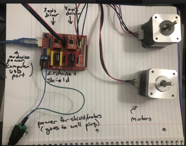
Descirption of parts: Shield/Drivers - we are using a driver module specific for arduinos. The motor we are using was made specifically with the intention of interfacing it with an arduino. The drivers/shields setup we are using will allow us to control the motor’s speed and direction with the arduinos while also regulating voltage between the low power consuming (about 5 volt) arduino, and the high-power consuming batteries. These are two seperate parts The drivers are placed on top of the shield. We used two drivers, placed on the “X” and “Y” axis of the shield (axis are labelled on the shield)
Our power supply for the motor will be a wall adapter. This type of motor uses either a wall adapter or a lead-acid battery, according to it’s battery datasheet. We ultimately decided to use a wall adapter.
Adafruit contained very useful information about the type of batteries that we would need and also warned us against connecting the motor’s power supply to the arduino’s power supply. The arduino controlling it will simply be connected to a computer USB port for power.
GRBL
To control the motors with G-code, we decided to use GRBL. This program is a free, open source, high performance software for controlling the motion of machines that move, that make things, or that make things move, and will run on a straight Arduino. The language it reads is G-code, which is the list of instructions often used for automated machines (i.e. CNC machines, milling machines, 3d printers…) to instruct the machines on what tools to move/how to move them, in order to make something.
First we had to familiarize ourselves with GRBL. We looked at these sites to learn how to install GRBL and also learn some basics as well.
How to install GRBL: site
GRBL is a very powerful software, but we had two main problems trying to interface it with our gantry system.
Firstly, our group’s gantry has two x motors moving in the exact same way. We had to figure out how to clone the movement of one of our X-axis motors.
Secondly, we do not have a “spindle” tool, which will cut material. Instead we have another motor, which only needs to turn slightly to enable a release mechanism for the batter.
We thought we had to rewrite GRBL code to do these two things, but we quickly realized there were much simpler solutions
Cloning the X axis: Sophia and Sydney
This video showed me that we could connect jumpers labelled “X” on the side of the shield, and connect another motor to the A Axis, and the movement would be cloned.
This seemed simple enough, but when testing it out, we found that the A axis motor would spin very quickly at the beginning, buzz as the original X axis motor turned, then spin very quickly.
I consulted Sydney, and after troubleshooting for a while, we sought advice from former Fabacademy student and node instructor Mr. Rudolph. He pulled up the motor drivers from the shield, and pointed out that there were pins under all of them. The pins were connected by jumpers on every axis, except the A axis (which was connected to a motor that was turning in an irregular way). The controlled rates of microstepping. Different combinations of the jumpers would result in reduced stepper seeds. One step is the norm, however, it actually takes a lot for a stepper motor to turn one whole step, and the stepper motor on the A axis was simply being told to turn so quickly that it couldn’t keep up, and turned in the irregular fashion we observed. The jumpers were in a 2x3 grid, and we referenced this chart to see which combinations led to which microstepping speed:
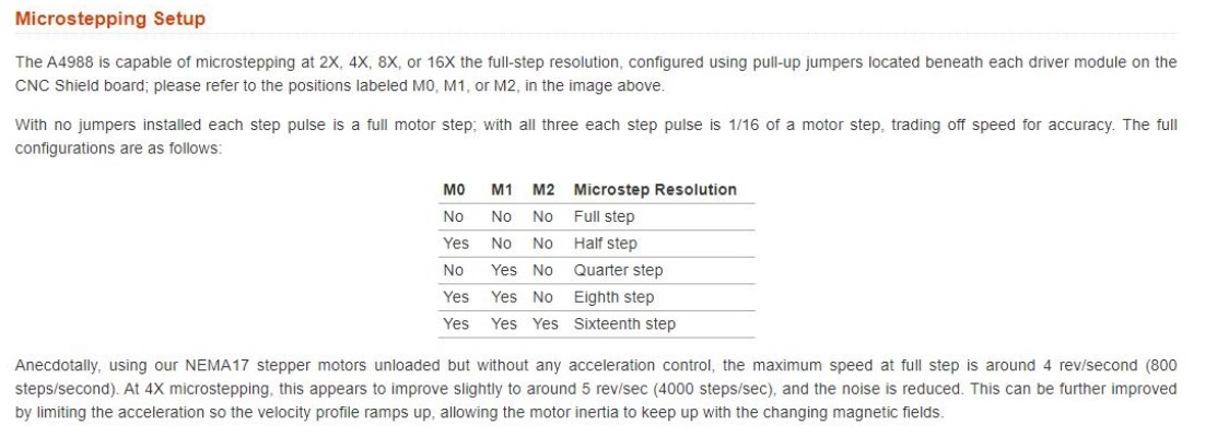
M0 M1 and M2 are the possible connections the pins can make. We chose to make all the motors operate at a uniform 16th step, for now.
Release Mechanism- Sydney and Sophia
Originally, our plan was to use a servo motor and attach it to the pins on the end of the shield, which are configured specifically for Servos’. However, Dr. Harris recommended we use another stepper motor, because then we can use one of the axes on the shield (the setup/commands will be uniform with the other stepper motors, instead of having a whole new servo setup/set of commands to deal with). He also recommended a very specific type of stepper motor (28BYJ-48)we had in the lab, which is very strong and would be compatible with the release mechanism, being designed by our peers Vincent Zhou and Harri Seto.
The one difficulty with this motor was that it was a unipolar motor, not a bipolar motor, which this shield was configured to work with. However, Unipolar motors and Bipolar motors utilize different connections between coils, however, the coils themselves are technically the same. So, we were able to change the wires of the unipolar coils, to make the motor function like a bipolar motor.
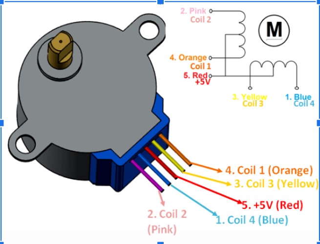
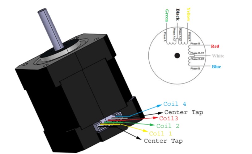
We found this YouTube video which explains how to do this. This website gave us a diagram of the colors and coil numbers and also provided the datasheet for the stepper motor.
Unipolar Motor wiring:
Bipolar Motor Wiring:
Bipolar to CNC shield:
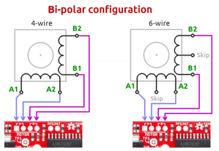
(4 wire not 6 wire configuration)
Using these diagrams, we were able to figure out which coils were which on unipolar vs bipolar motors. As long as the wires line up (coils 1, 2, 3, 4 or coils 4, 3, 2, 1) when they are plugged into the shield, the motor will function. If the motor spins in the wrong direction, simply flip the order of the pins.
| Unipolar Coil | Bipolar Coil |
|---|---|
| 1- blue | yellow |
| 2- pink | green |
| 3- yellow | red |
| 4- orange | blue |
Here is what the shield looked like in the end
GRBL controlled by GRBL commands- Sophia
GRBL is only the protocol that the arduino runs. GRBL has a set of commands which will communicate G-code to the motors. This is the simplest way to control the machine, and it gives the machine free mobility. If you look at a normal milling machine there is usually a command functionality that allows you to move the tool freely. However, there is also a component that allows you to load G-code in some way. The G-code send the tool in complex toolpaths, and is capable of making all the beautiful creation we’ve seen come out of CNC machines, milling machines, 3d printers (an additive version of this), etc. Right now, we will focus on simple commands.
Fortunately, the Arduino IDE has a built in Serial Monitor, which can be used to send the commands. Otherwise, we would have to connect some terminal or other program to our Arduino board.
The only steps needed to do this are Download GRBL Determine the settings for your specific machine Send commands
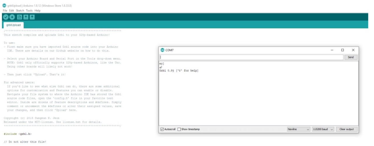
This instructables tutorial goes through the steps to download GRBL-master as a .zip, extract it, and load the “grbl” subfolder into the Arduino IDE as a library. Once you do this, you simple open the code through examples, flash the code, and then GRBL is on your arduino.
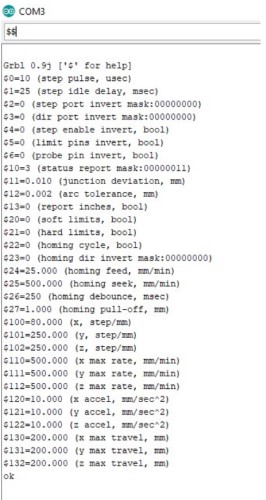
Once you do this, you can open the Serial Monitor to start communicating with GRBL. One you set the Baud rate to 115200, the last line on the serial monitor below will appear:
We used the GRBL wiki as a reference for commands. We also used this site to specifically learn how to move one axis at a time. The most basic commands:
X movement command- “G0Xn” Y movement command- “G0Yn” Z movement command- “G0Zn”
“N” is the variable that can be subbed in for any number of steps.
We did not need to do “G0An” because the A axis was configured to clone the X axis, and therefore would move whenever the command “G0Xn” was used.
At this point, we configured the settings for our machine. Firstly, we needed to change the steps per mm of our motors. GRBL takes inputs in mm, but the motors use a unit called “stepps.” To get an accurate distance travelled, GRBL needs to know how many steps correspond with how many mm for our specific motors. The integrity of our cupcake gantry depends on it. We used the Nema 17 motors for the gantry, and used this calculator for our measurements.
Most of the information we needed was on the component’s datasheet. The microstepping value was 1/16th, because this is what we had set it as earlier by connecting the M0 M1 and M2 pins.
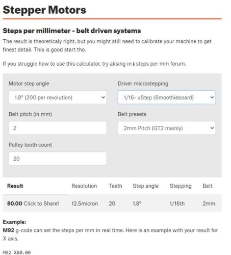
Nema Motors have 80 steps per 1 mm. The Nema motors were controlling the X and Y axis. To change the default steps/mm in GRBL for the X axis, you type “$100=80.00”. To change it for the Y axis, you type “$101=80.00.”
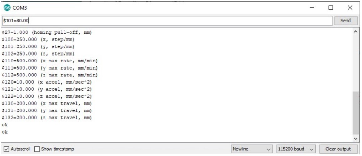
The Z axis is controlling the 28byj-48 motor, and that measurement does not control either of the axis we are using, so it doesn’t need to be very precise. It simply needs to turn approximately 90 degrees, then turn back to 0 a few moments later.
We did not change any of the other settings. We considered changing acceleration, but the defaults were all pretty reasonable so we left them alone. When we integrate the motors into the gantry, we may change this, because we do not want the gantry to move too slowly/too quickly.
GRBL controlled by G-code: Sydney
There are a couple of different ways to write G-code. Since it is such a complex set of instructions, usually programs like Fusion 360
After a discussion with our teacher, he told us that it would be best and very possible to write our own g-code from scratch which would probably have around only 50 lines. I wanted to create a rough draft of the code, leaving out the details, just to have an outline that we could fill in and edit later. Because I am relatively unfamiliar with the language, I took some time to read through some info about the language. First and foremost, I needed to know how to start the code. This write up from Autodesk was very informative on getting started and the necessary basics of Gcode. I learned that g-code stands for “geometric code,” and follows some variation of the alpha numeric pattern: N## (line number) G## (Motion) X## (Horizontal Position) Y## (Vertical Position) Z## (Depth) F## (Feed Rate) S## (Spindle Speed) T## (Tool Selection) M## (Misc functions) There’s also I and J which are the incremental center of an arc and R which is the radius of an arc. G defines the motion and function, XYZ declare the position, F and/or S set a value, T selects an item, and M switches things on and off (ex: coolant, spindle, etc.)
According to Autodesk, g-code tells the machine to do one of these three basic motions and how to do it: Rapid move: a linear move to an XYZ position as fast as possible Feed move: a linear move to an XYZ position at a defined feed rate Circular move: a circular move at a defined feed rate
I just wanted to get started with messing around with g-code, so I used the website-based program, Chilipeppr to do some hands on learning.
First, I had to set up the serial port JSON server. This honestly took me a bit to figure out because in the video that I was using, the site sent them directly to the set up of the port whereas now, it sends you to JSFiddle. I simply ran the code, and the same screen as in the video showed up in JSFiddle.
Why this is important: We know exactly what our cupcake system requires. It would be much easier to upload all that code at once, instead of typing in codes manually. Also, understanding how to send G-code opens the potential to use the gantry as a complex machine like a CNC machine or a milling machine of some kind.
Here is the link to the group site with the finished product!
Files: