4. Computer controlled cutting
This week there was a group assignment on characterizing our laser cutter and an individual assignment on vinyl cutting and creating a parametric press fit kit. Part of this week’s assignment was to work as a group and characterize our laser cutter’s focus, power, speed, rate, kerf, and joint clearance.
Group Assignment
I worked a lot in the beginning to define all these terms and come up with a plan for how we were going to find each of them, and documenting it all. As we ran into problems and our plans changed, we individually edited documentation for our specific parts. We initially did not understand the assignment very well but were able to figure it out with the help of google and our Fabacademy node instructors’ help. Once we had a plan I worked on designing a simple corel draw file that we would measure kerf on and printing it out. I later helped laser cut more objects and went through the process of characterizing kerf + joint clearance and helping print and characterize power.
To see a more detailed description of our work, go to our group site
Individual Assignment
Press fit kit:
Part of our assignment was to use our newfound knowledge of the laser cutter to create a kit of parts that can be assembled in lots of different ways(like having lots of slightly different leggos to fit together). I heavily depended on the fab academy archives to figure out exactly what was expected. Another requirement was to make our designs for these kits parametric. This means the dimensions of the facets will have to depend on variables that can be changed. This will be very helpful as I try to change the scale of dimensions. Usually this is a very meticulous task for me, but designing something parametrically will cut out struggling in the end to make everything fit together when other aspects change, without having to redraw the entire design.
I also browsed a lot through google to help supplement my complete unawareness of what a press fit kit was. I eventually stumbled upon this source which I thought was incredibly cool as inspiration, because here it was used for a dome, and lots of small triangles and joints will allow for lots of detailed creations! I probably won’t make nearly as many triangles, but their versatility really attracted me to this idea.
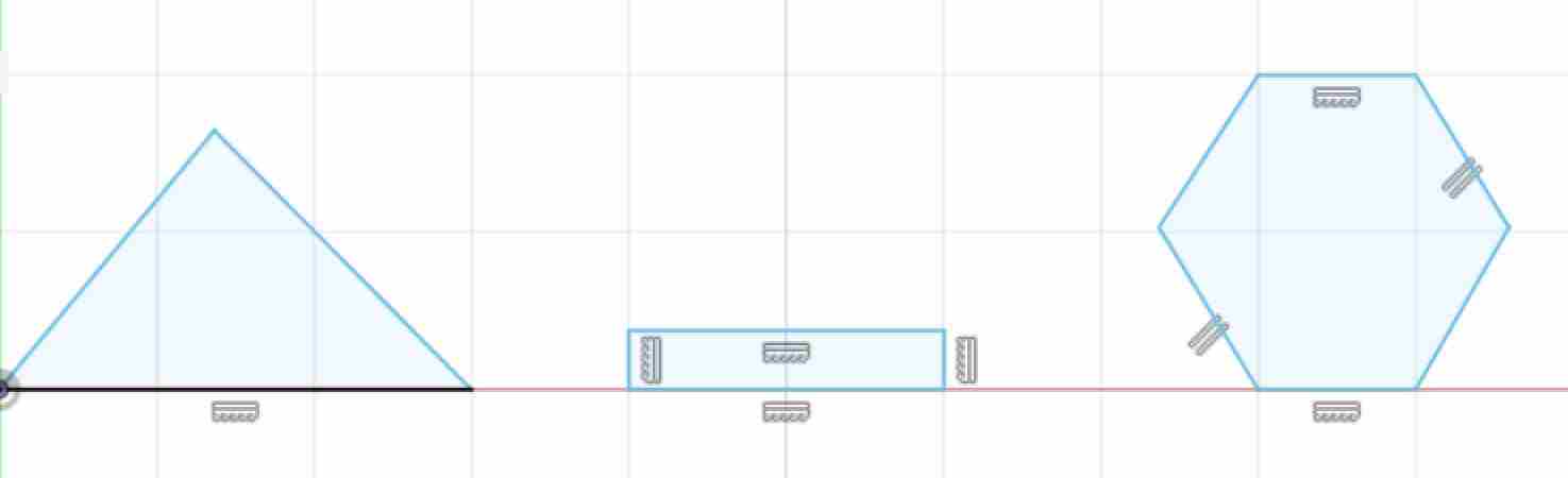
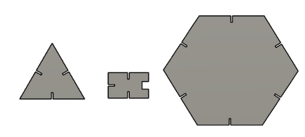
I started by making some very simple shapes- a triangle, a hexagon, and a smaller rectangle (to act as a joint for the larger parts). I paid little attention to their initial sketches. Check out my Week 2 documentation for more detailed explanation on the specifics of how I am executing all these steps, by the way.
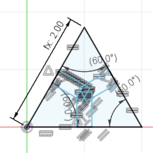
I then began to apply constraints to the dimensions. I set all the sides and the angles of the triangle and hexagon equal (separately). Trying to set dimensions on the angles threw an over constraining error, and prompted me to set the dimensions as “driven dimensions” (meaning they would change as the other dimensions changed. It also didn’t allow me to set constraints on every angle (again, overconstraining it). I think all the angles will change anyways, because of the nature of hexagons. When some angles are the same, the other angles will be forced to also be the same.
However, I still made these “driven dimensions” with the hope that I will be able to see the angles changing as I alter my design in real time to confirm that they do stay equal. The rectangle, by virtue of me drawing it as a rectangle, was already constrained as having opposite sides be parallel and equal, and also be perpendicular to the other sides.
I realized I also had to draw the slots on the sides so the pieces could fit together. I made some basic rectangles next to each face. I then went through to make sure all the parts I cut out so they could be pressed together, so once I came up with a parameter I would only have to apply it once and everything would change with it.
After placing about 80 billion different constraints but still not placing any dimensions, I got this:
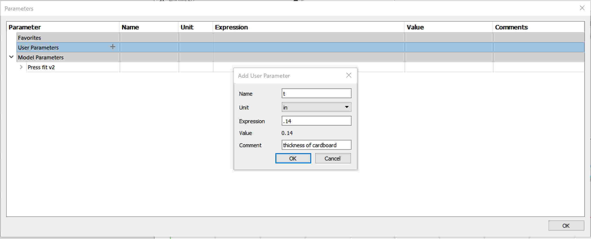
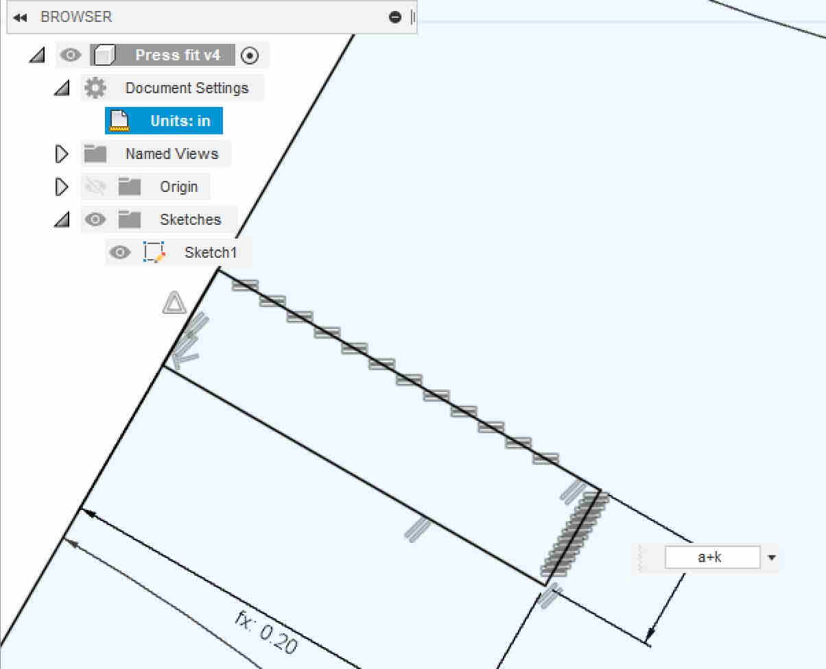
Finally, I navigated to “Modify” then to “Change Parameters.” Next to “Change User Parameters” on a pop-up menu there was a plus button, which I clicked, then made my first parameter called “t.” This will be for the thickness of the pieces, probably .14 but it’s of if that wrong because it is an easily changeable parameter. I also changed units to inches. I hadn’t done this in the beginning, but I then went into the “Browser” right hand menu and changed the units.
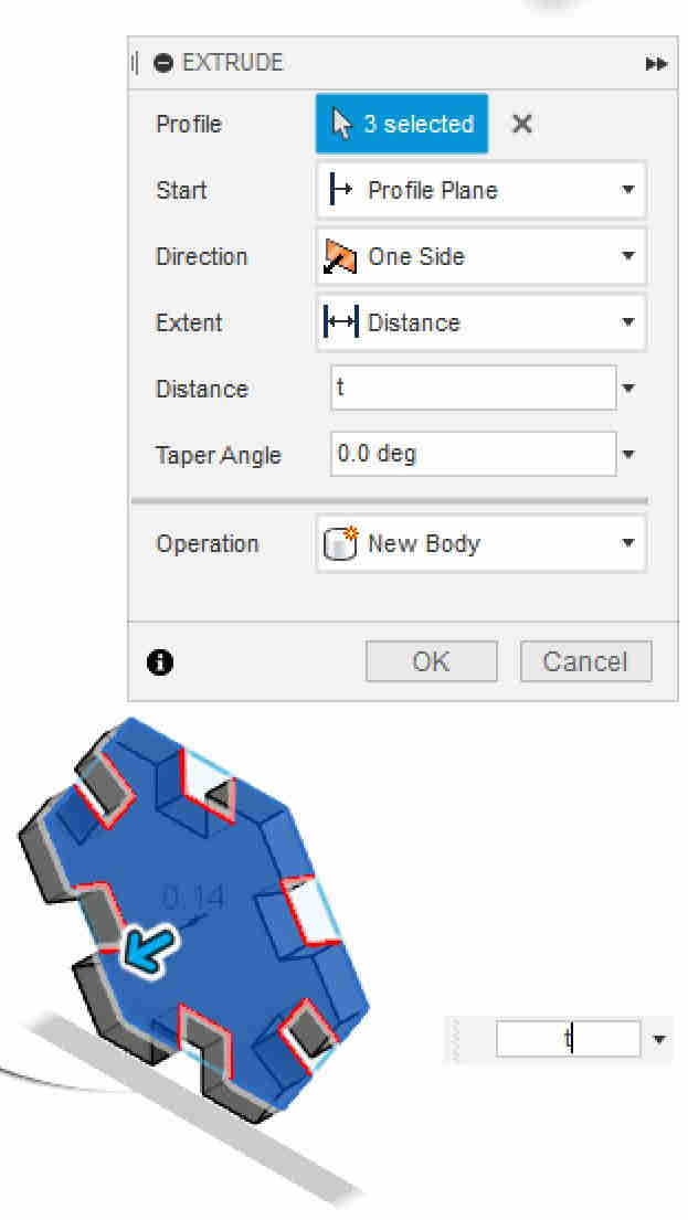
I then extruded my sketch objects with the thickness of parameter “t.”
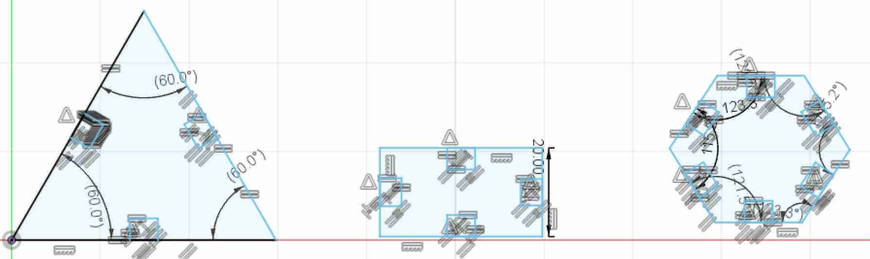
I then created a few more constraints to make the tabs be the same length/width, and have the sides of the triangle and hexagon be the same.
I tried to change the parameter to 2 inches within the menu, but parts of the triangle(that I hadn’t se parameters on yet) tried to scale themselves and ended up overlapping:
So the triangle got mad at me and removed its body when I exited the sketch. I set the parameter back to its original settings and edited all the parameters so they were based on the bodies they were a part of then tried rescaling again.
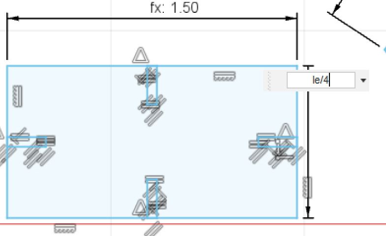
And it looked like this! One pesky tab was left out so I fixed that. I then set the box length as a parameter and the width as just ¼ of the length.
Then I suddenly remembered I had failed to take into account kerf for the laser cutter. Our value was .005 inches. I made a parameter for kerf and added it to the dimensions of my tabs so I would have a better fit. I did later decide to change my kerf value to .004, because I didn’t want the fit to be too tight.
I also noticed that my tabs on the vertical side of the rectangle were very big compared to the rectangle and would compromise its ability to hold anything, so I deleted them and just left the two on the horizontal sides.

I was also chatting with my peers in the Latin Lab, and I found out they were chamfering all their edges so the slots went together easily. I decided to add this as my final parameter. Final parameters:
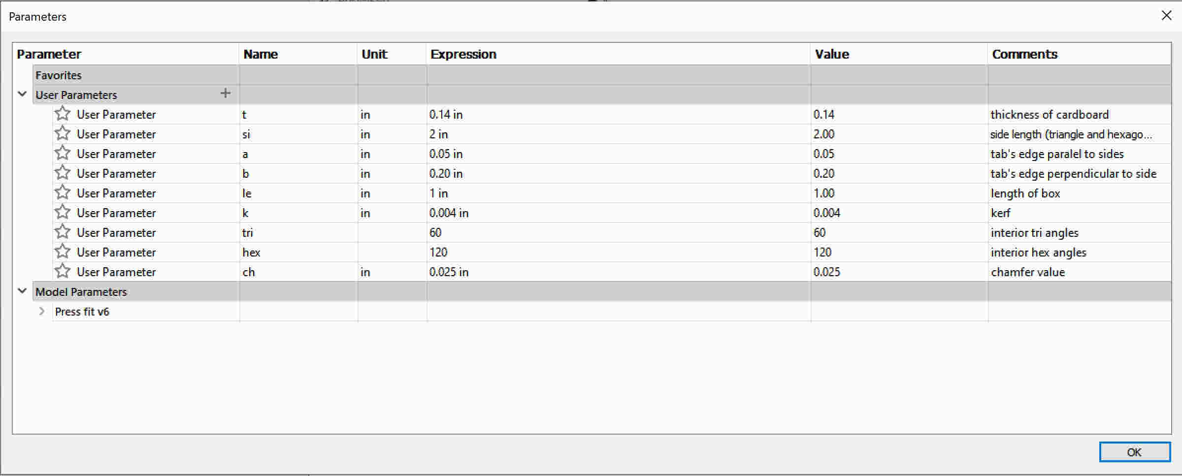
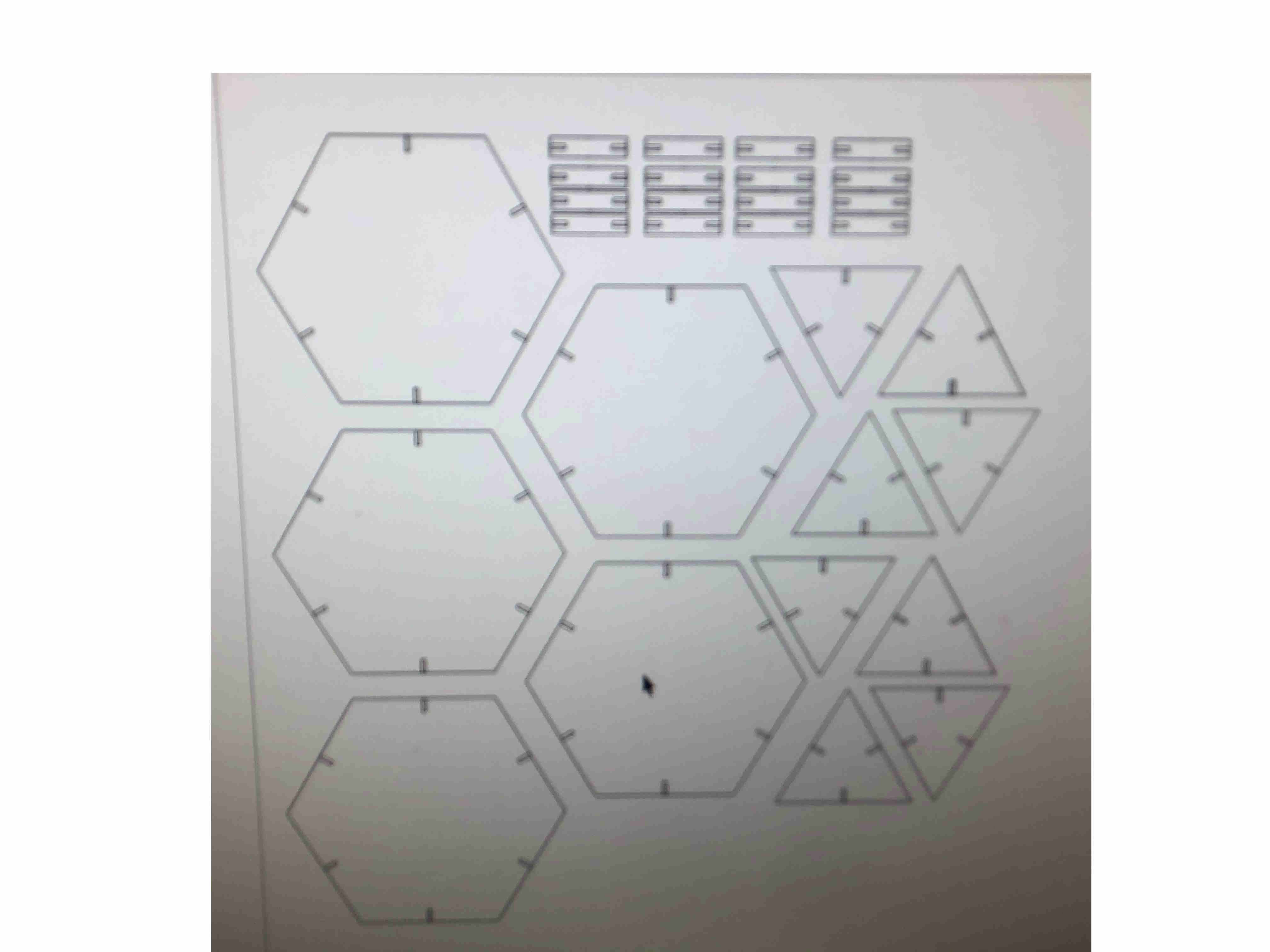
Final product:
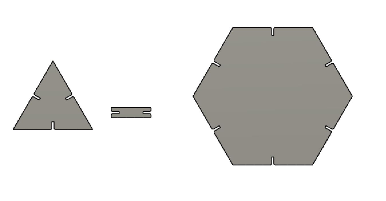
Voila! Design done. I then exported it as an SVG and brought it up on our laser printer. I then exported the file as a .DFX from fusion and brought it to the laser cutter. The model of our laser cutter is: Fusion M2 32 / 40 Laser System (Model 13000 / 14000).
I started by ungrouping all my objects, regrouped the original shapes, and made rows and columns of my design. I wanted as much of the design to fit in as little room as possible (to maximize the number of cutouts I could make).
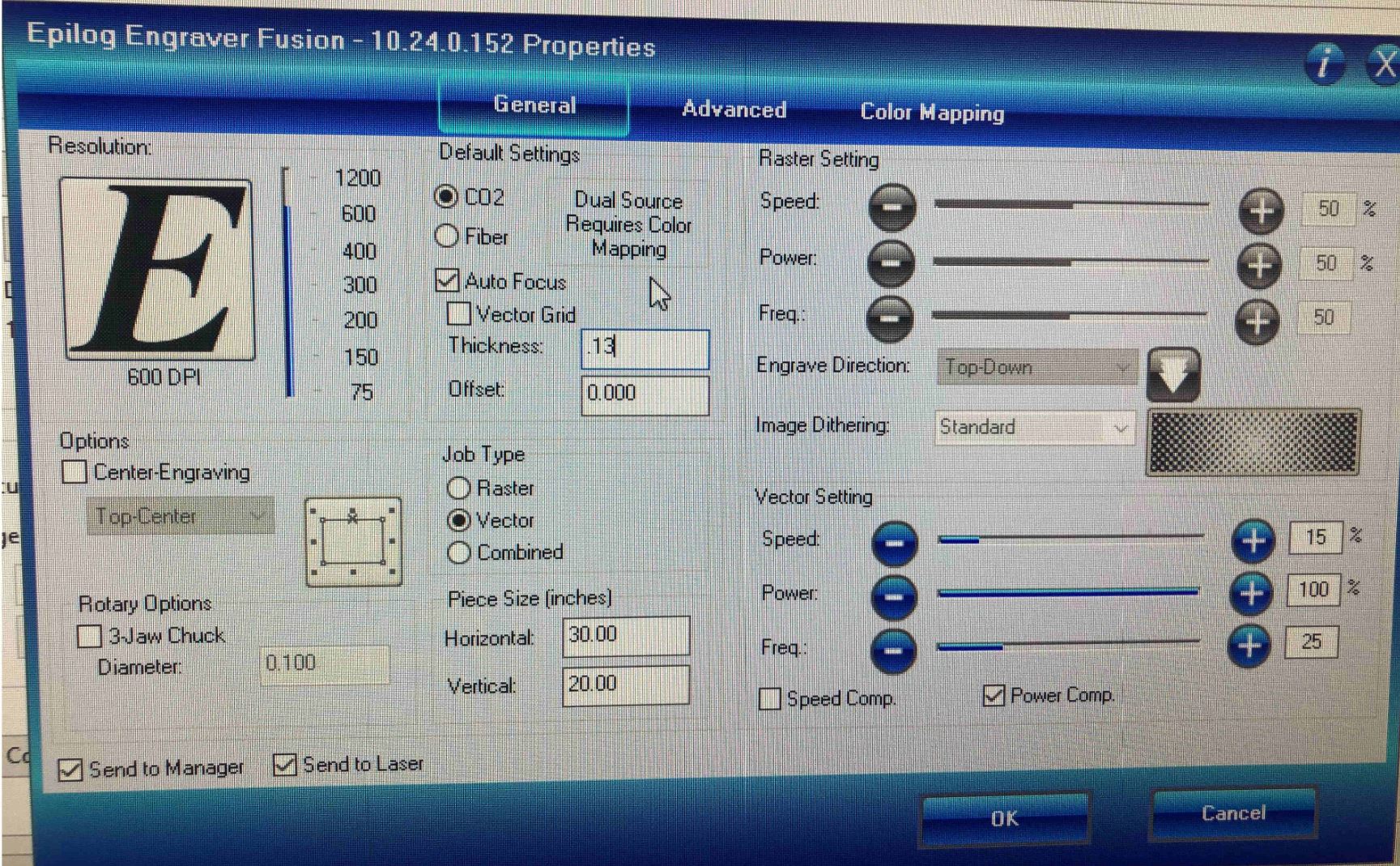
I then went to “File,” “Print,” “Preferences” to change my settings to what they needed to be for the .14 inch cardboard I was using. I set the speed to 30%, power to 100%,and frequency to 25%. I made sure the “Job Type” was set as Vector. Unfortunately, The first time I tried to cut my shapes, I forgot to turn on the “auto- focus”button and set the thickness of my cardboard. This drastically affected my cuts so I ended up having to redo it. Correct preferences:
I also noticed that my tabs were way too small for anything to fit, so I went back to my file and changed their values so the tabs would be .05” by .3”.
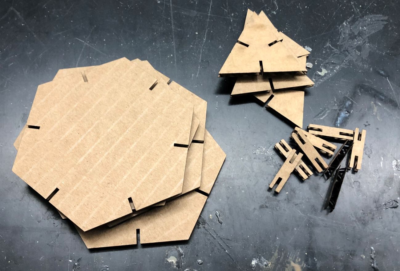
Photo without autofocus: (I also cut the scale in half and had very tiny tabs that later changed)
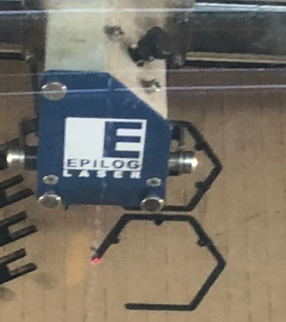
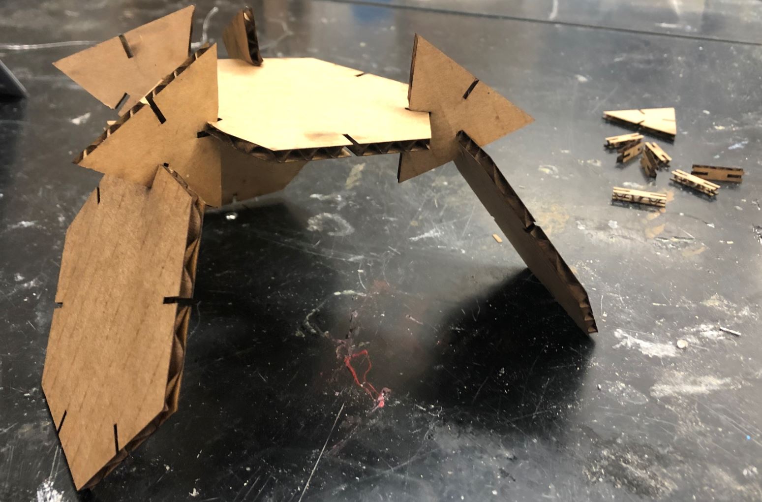
Photo after autofocus:
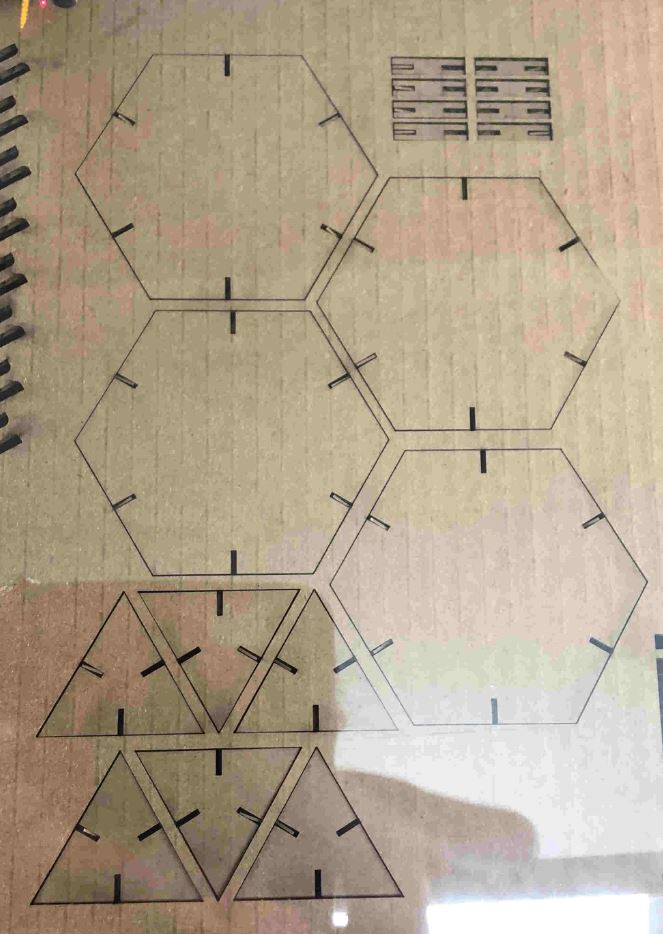
Making these changes drastically fixed the way my laser cut came out. I was very pleased with the second version. The tabs were a little tight, I definitely had to jam them in there, and I believe my chamfer was too small to really show up. Next time I will make my chamfer values a little higher. I believe the tabs were too tight because my kerf value was a little smaller than it should have been (I was afraid they would be too loose) but they still fit fine.
Vinyl Cutter
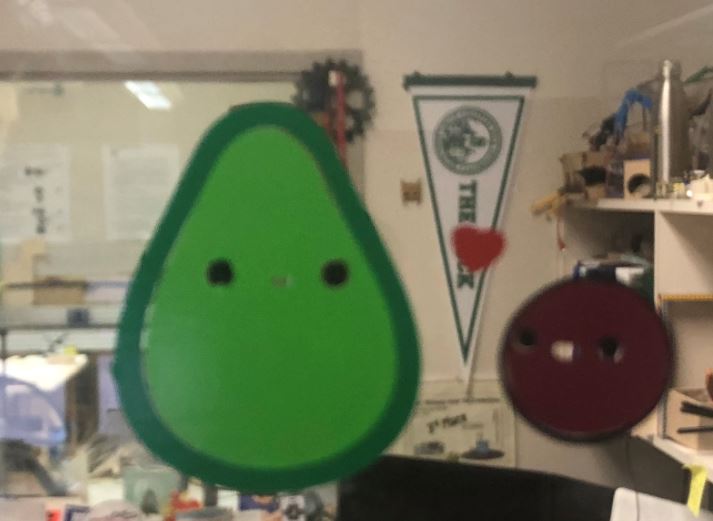
The last part of the assignment was to cut something on the vinyl cutter. I found a cute avocado clipart online, and decided to make that!

I originally wanted to do it in inkscape (that is what I experimented with last week) but I didn’t love that program so I decided to try drawing on Corel. I can’t get Corel on my own computer, so if I have to do 2D design at home I will go back to inkscape, but I will be able to experiment with Corel while at the lab.
I imported into corel draw and took a minute to click around the menus. This wasn’t the first time I had used Corel but most of what I had done was very basic. I didn’t know how to trace things.
 (Image of menus)
To trace the image, I first tried going to the “Bitmaps” drop down then selecting the “Centerline trace” feature using the “Line drawing” option, because a [tutorial] I found suggested it . I seletcted “line-tool” however the program preview only showed me one stray line traced around the big avocado, so I realized this wasn’t what I was looking for.
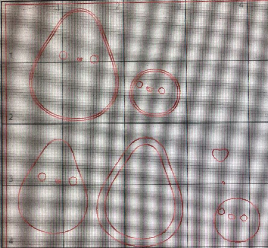
I then tried the “Outline Trace” tool with “Line Art” under the same Bitmaps menu that I saw. T showed me a preview that was more similar to what I was looking for:
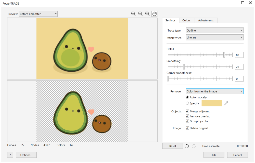
Note: If you zom in things are a little fuzzy. Obviously, you should use the highest resolution image you can find for this tool for the best results. I did think the “smoothing” setting helped to make up for any errors I would have had because of resolution.
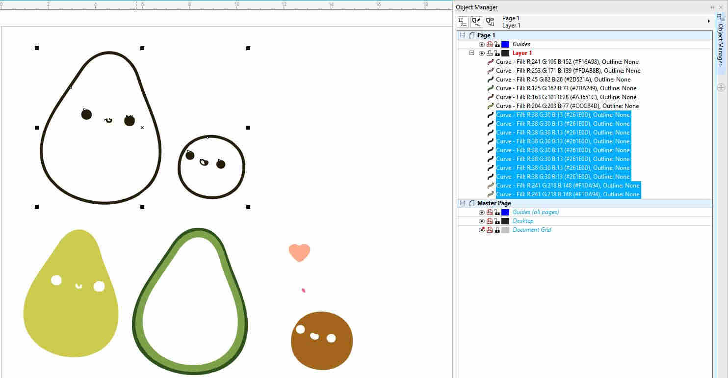
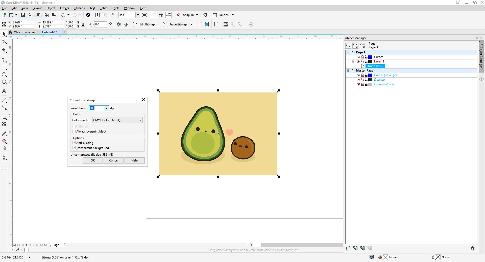
It also looks like all the trace did was remove the background. If I clicked on it and dragged it around with my mouse, I could see that there was a bitmap outline of just the lines uner the colors. I needed to ungroup them all so each one could be cut individually as a different color. After clicking around for a while I realized that I could go to the “Objects” menu at the top, navigate the “Groups” and choose the setting “Ungroup all objects.” I could now move them all around. The left sidebar shows more details of this. I then moved everything around and grouped all the different colors together.
Note: In the photo I grouped two of the green objects together. This is because we only have 2 different green vinyl color in the lab. Later I just deleted the inner ring for simplicity.
I quickly deleted the inner ring then exported it as an SVG, and opened it on the vinyl cutter software “silhouette studio.” I just had to drag and drop the downloaded file in. I then selected the “trace” menu (that looks like a butterfly on the left toolbar). I navigated into “select trace area” and dragged my curser over the images I wanted to trace. I traced each of my colors separately.
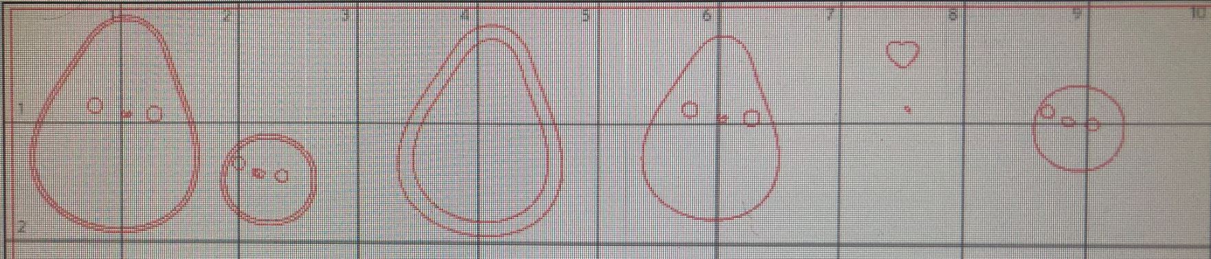
I selected “solid fill” trace and then selected “trace” to apply my changes at the bottom of the trace menu.
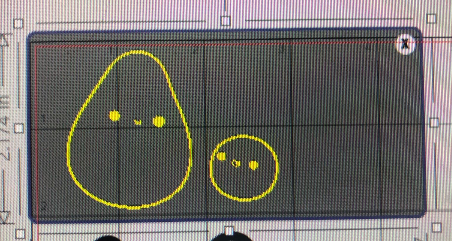
I deleted the original image and arranged the objects on my page. I kept all the different colors with each other so I could cut multiple parts in one go. The board the stickers go on has a grid, so it was easy to line up with what I put on the computer. I was afraid it would mess up though, so I had to be super careful.
To set up vinyl cutter: 1. Put vinyl on board 2. Press vinyl down on flat surface 3. Load mat into cutter 4. Navigate to send in the software 5. Try a test run (bottom left corner) 6. Hit send to cut 7. When job is complete and cutter stops, press “unload” on the cutter
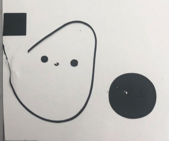

I separated the parts of the sticker I needed from the excess. Unfortunately, I lost the mouth of the black part and the outline of the avalado broke. In hindsight, I’ve always been terrible at manipulating very tiny pieces of stuff. I don’t really know why I forgot this important detail when choosing this sticker, but I’m going to do my best to make it work anyways.
Anyways, before I put the sticker wherever I want it, it needs to be moved to transfer paper so all the parts are together and the sticky side is facing up (right now the sticky side is down.
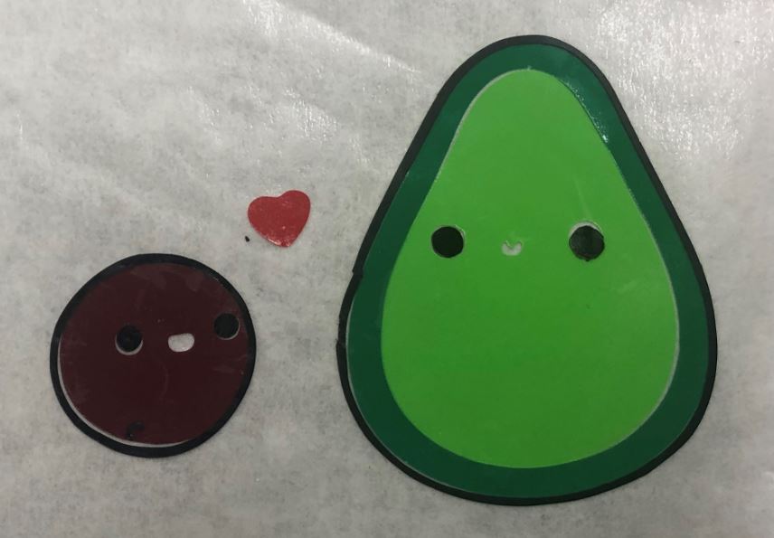
I put it on the window. Final product! I got an air bubble under it the first time so I tried to peel it back and fix it, this just made my parts further away from each other. I ended up taking the thin black outline off the avocado because throughout this process I pulled on it enough times that the vinyl started to warp :/.
For the most part, I think it looks ok. In the future I would like to keep experimenting with stickers and the best way to handle them after I have to depend on my hands, and not super precise machines. I think if I had layered the sticker’s layers from the outside in while attaching it to the transfer paper, this avocado would be a lot smoother. I also don’t love the color of the pit (that color is pit-fully bad) but I think it’s mostly ok, otherwise!