12. Output devices
Group assignment
Measure the power consumption of an output device
Document your work (in a group or individually)
Individual assignment
Add an output device to a microcontroller board you've designed and program it to do something
Individual Assignment
BLDC Motors
For this week’s individual assignment I will be making an output setup that controls a BLDC motor. I need these motors to control an omni wheel drive that will propel a bb8 robot in my final project. I chose to use DC motors because they are better for projects like mine because they have a higher RPM. I chose to use BLDC motors (Brushless DC motors) because they are more efficient, quieter, DC motors.
BLDC motors work by spinning a rotor made of a ring of permanent magnets. The rotor spins because it generates a magnetic field, and the 3 wire coils with current passing through them encircle the magnet (which means they can feel the rotor’s magnetic field. The magnetic field causes a force to be exerted on the coils with current, and the force pushes coils. Since the coils are stationary, the magnetic rotor spins.
Designing the Board and Milling
Niel’s setup for a BLDC motor looks like this:
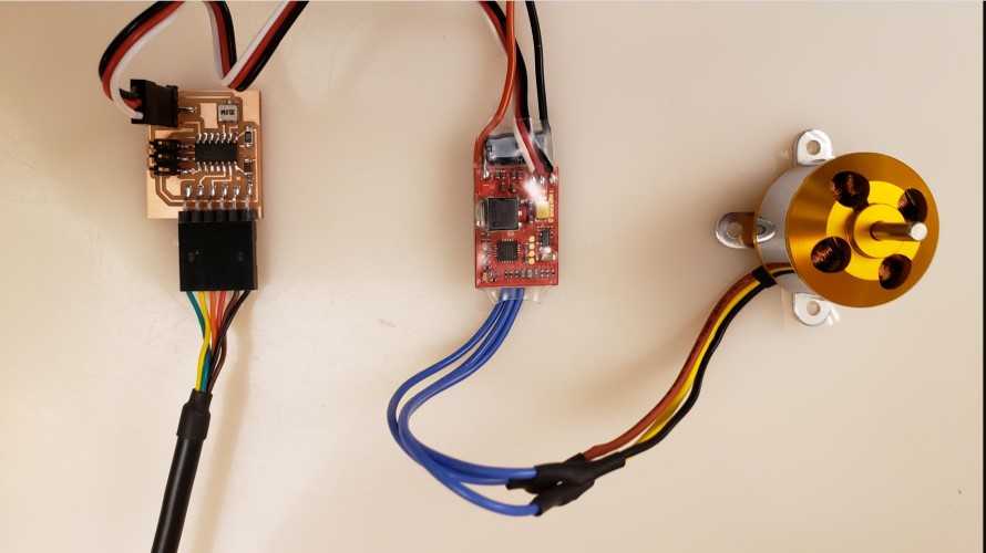
Obviously there is the board, the motor, and the red thing is an Electronic Speed Control for Brushless Motors (ESC). ESC’s are responsible for two things in this case: They have the H-bridge circuit and they regulate the current.
An H-bridge is a special type of circuit that creates two paths for electricity to flow into a motor. This is because the path that current takes through the motor will affect which direction it spins. One path is for clockwise spinning, the other is for counterclockwise. You can toggle between which path is open and which path is closed to change the direction of the motor.
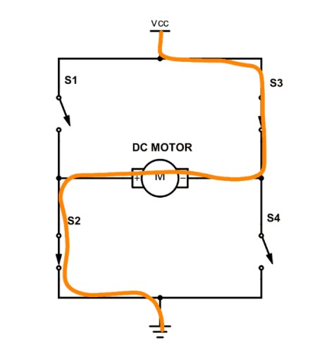
(One path example)
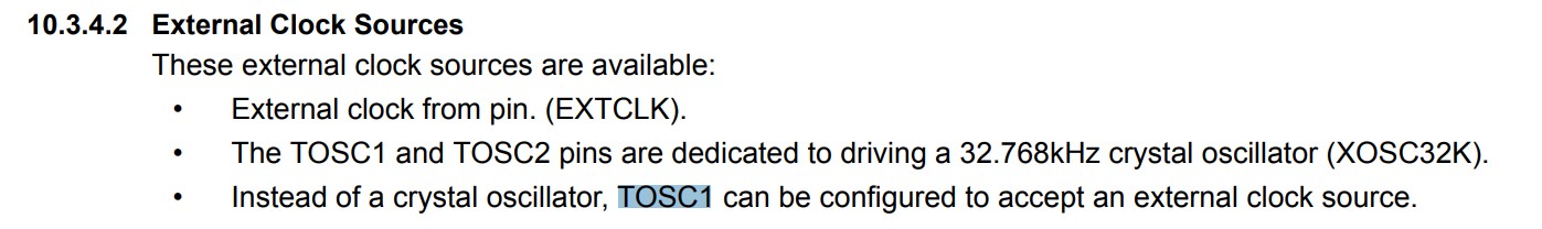
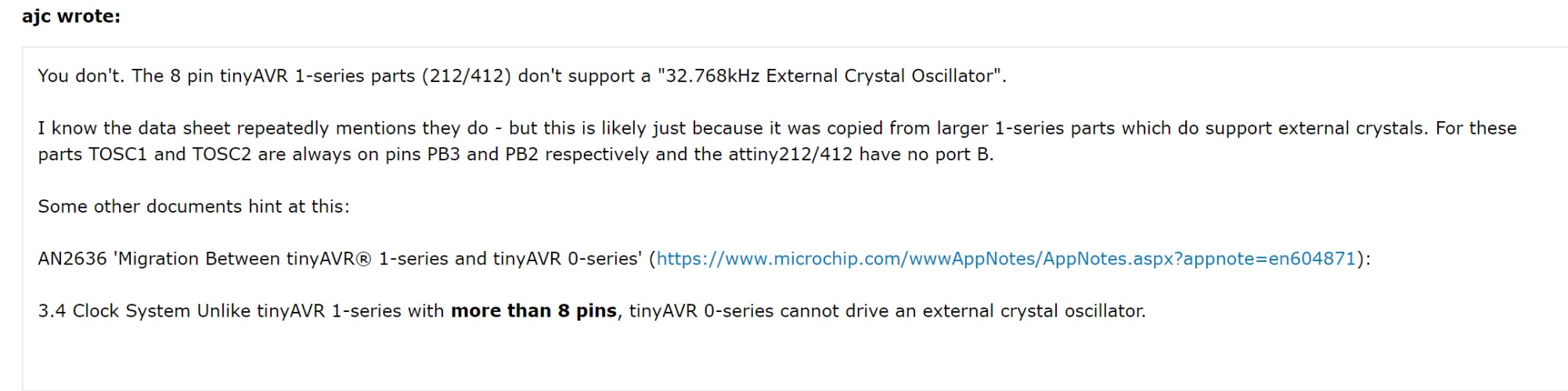
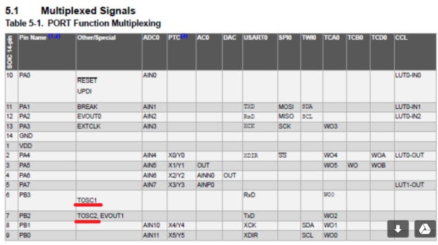
The other thing the ESC does is control the current. Motors require a high amount of current to function, while attiny’s and their breakout boards take a very small amount. Obviously, if we send the current through the breakout board, it will be fried. The battery connects to the ESC and the ESC makes sure that the high current doesn’t reach the attiny. I will connect a battery to my ESC so that the high current goes to the motor. I also wasn’t sure which pins the 20mhz external crystal oscillator was supposed to be attached to. The datasheet says TOSC1 and TOSC2 pins are what drive external clocks. I believe I may run into an issue with the attiny412 and these pins, because some sources claim that they have these pins and others claim it is a mistake. Either way, the TOSC1 and TOSC2 pins are supposedly on pins PB2 and PB3. so being used for the TX and RX communication pins, so I am afraid I will run into a problem trying to control two different things with the same pins. I thought about switching microcontrollers, but I don’t believe I have access to any ones that have all these pins separately. If this happens, I will remove the oscillator and try to change the clock frequency with software.
I also had to download some parts from external libraries. I found the 20 mhz crystal resonator and the ESC connector on SnapEda. Once I downloaded the files, I extracted them into the libraries folder of Eagle.
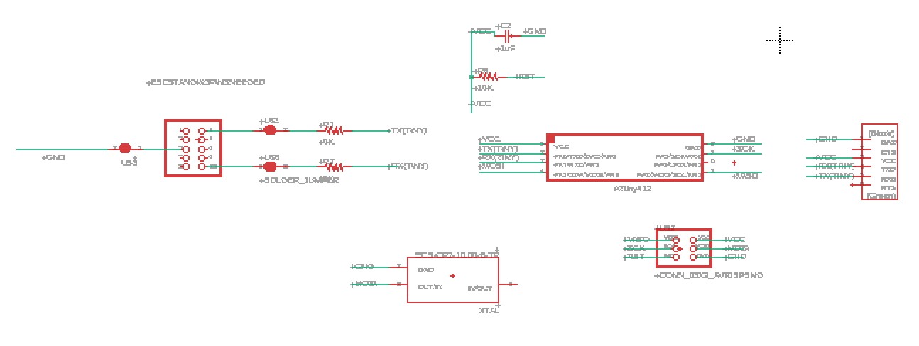
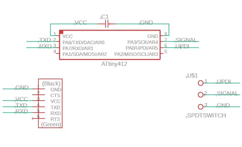
My schematic looks like this:
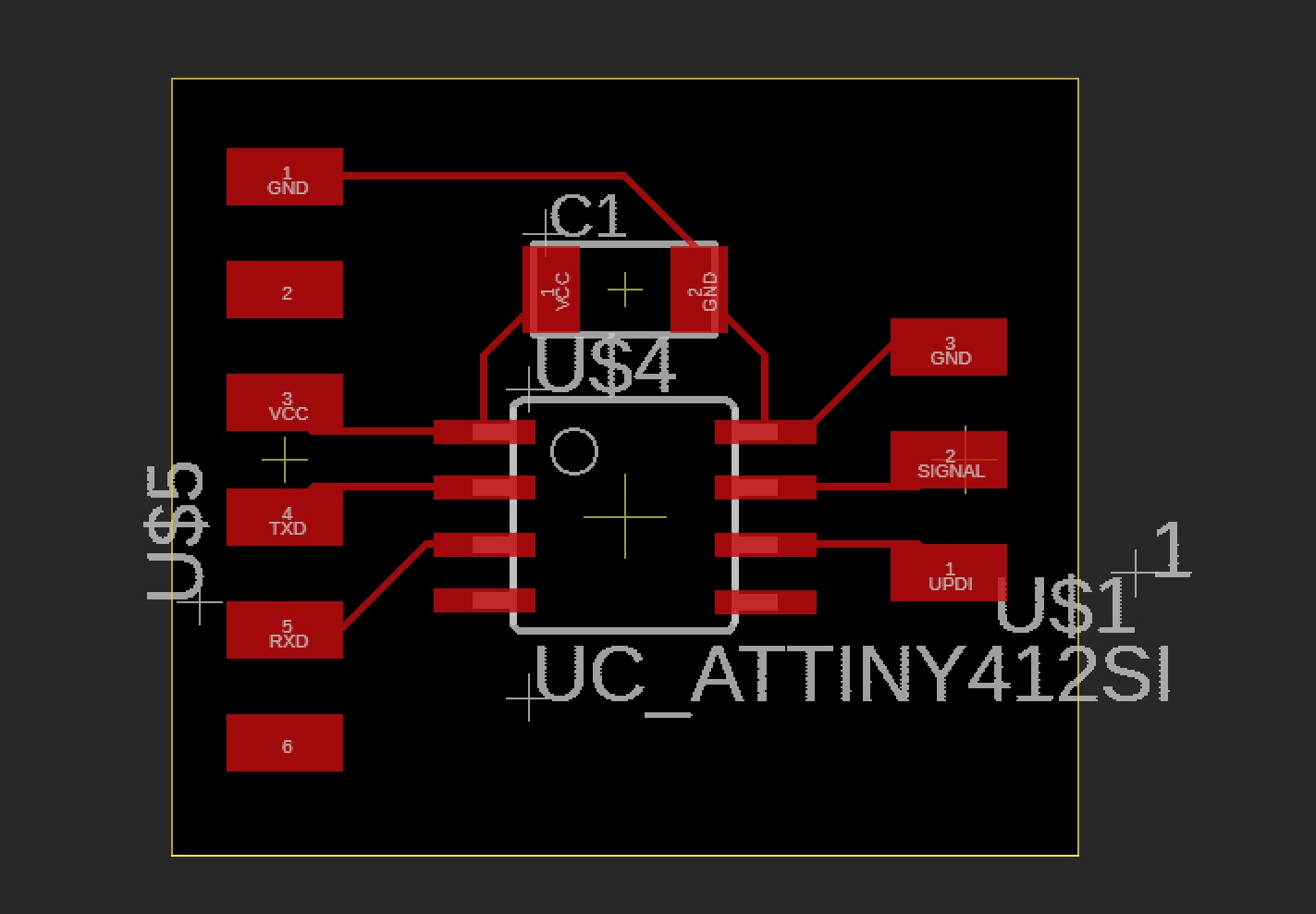
My board looked like this:
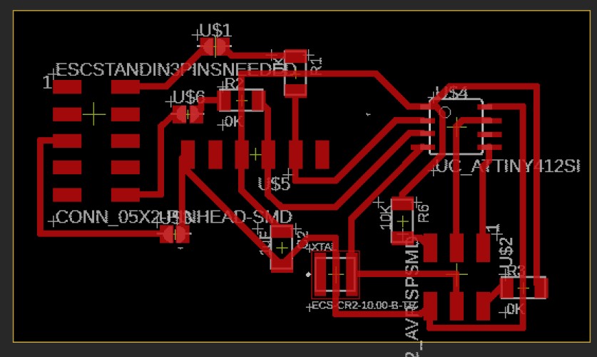
Because there is higher current, all my wires and traces did have to be thicker. I used this Trace width calculator to determine a vague estimate of the width of the traces I needed for the parts I was using. You may notice that there is a 5x2 pin header at the side of the board, and solder bridges attached to them. This is because I knew I needed 3 connections to the ESC, but while I was designing the board I wasn’t sure if I was going to use an ESC that had pin headers attached or just raw wires. If I needed to solder raw wires, I wanted to have lots of space to do it. The solder bridges were because I was still learning what the ESC needed to be connected to, and I wanted a way to disconnect the pins easily in case I needed to completely change where the ESC pins connected to.
As of right now, I do not have access to a milling machine because our lab was shut down because of COVID-19. However, a teacher was able to mill it for me and send me the parts. To see my milling work while the lab was not shut down, refer to week07, Electronics Design Week..
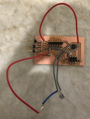
Here is what it looked like after soldering:

I checked all the components with a multimeter then connected the board to an arduino, the ESC and the motor and prepared to program.
Problems with board
As I connected the ESC, I realized I had made a mistake. The ESC went to the TXD and RXD pins on my schematic. I believe I confused it with the external clock, due to the fact that the name of the external clock was “Ecs-cr210-b-tr.” The two connections that I actually needed for the ESC were connections to ground and attiny pins that went to PWM). I didn’t need 5v because we don’t want the power supply of the motor and the Breakout board flowing to the part they aren’t supposed to power, we need to leave the 5v pin disconnected on the ESC. The connections I actually needed: ECS to GND ECS to PWM (PIN_PA3 on 412) Clock to GND Clock to PIN_PA6 and Clock to PIN_PA7 I used the solder bridges and extra pads to break connections and make the correct ones.
After I fixed everything, the setup looked like this:
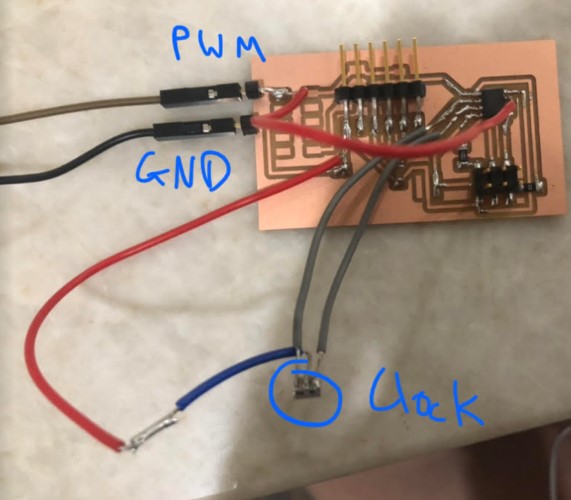
I also missed the UPDI pin, somehow. I accidentally made a lot of connections that made sense for the Attiny44 but not for the 412. The next photo includes the UPDI pin (the only pin added after the last photo)
I referenced this video to set up the motors and ESC, because I didn’t originally recognize the colors of the wires. Basically, the motor has three wires. These connect to the three black wires on the ESC> The ESC has two large wires, Red and black (ground and VCC/voltage in) and three small wires were voltage in, ground, and signal. The two big wires go to the GND and VCC of your battery. You connect the smaller wires to your board. GND and Signal wires go to GND and signal (PA3 for me, since at the time I thought that since it was the Attiny412’s PWM pin, I had to use it for signal). You don’t connect the breakout board to the voltage of the ESC, because you don’t want the high voltage of the battery connecting to the low voltage attiny412.
Programming
I wasn’t sure that Niel’s code was going to work for me because I had already found a lot of differences between the attiny44 and the 412, but I tried it anyway. After configuring my arduino as a jtag2updi programmer and attaching it to my output breakout board, I configured PA3 as my PWM pin, PA6 (TDX) as my serial output and PA7 (RXD) as my serial input. However, I ran into this error while compiling:
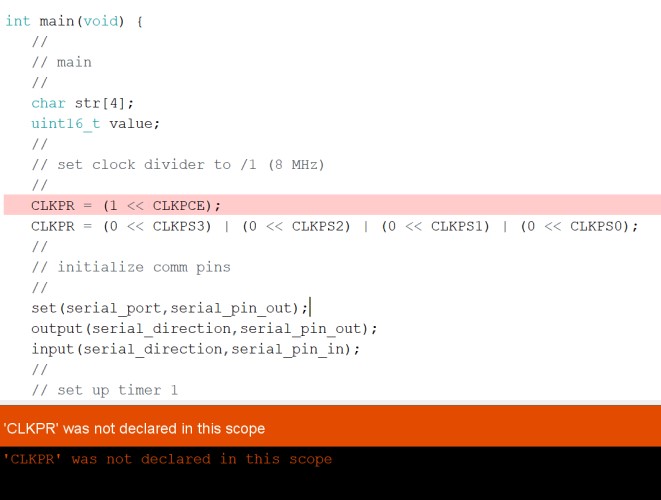
This seemed to be an error with setting the clock frequency. One site
I troubleshooted for a long time but couldn’t figure it out, so I contacted one of my teachers.
More problems with the board
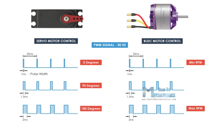
After troubleshooting how to fix the code I talked with one of my teachers Mr. Rudolph. He told me that because the attiny412 was configured so differently from the attiny44, and that’s where most of my problems and questions were coming from. He let me know that I could completely remove the external clock aspect, since the clock inside the attiny412 could already operate at 20mhz the external clock was unecesary. He also informed me that a BLDC motor and a servo motor functioned very similarly, and that I should look at servo code to setup my code.
My board is a bit of a mess, it has too many extraneous connections. The only connections needed are VCC, GND, TXD and RXD for communication, a UPDI connection for programming, and a connection to a signal pin for the motor. I also wrongly assumed that using the PA3 attiny412 pin was necesary for seding a PWM signal. Both servos and BLDC motors can be controlled by any signal pin. This site discussing interfacing BLDC motors to arduinos (and how the proccess is similar to servos) was helpful with that.
Here is a minimal board, that I will mill and test later.
Back to programming
I used the servo.h arduino library for this. You can use this servo code because Servo Motors and ESCs use the same 50hz pwm signal. In the case of the BLDC, the code will change the RPM of the ESC instead of the position.
I used the example servo sweep code (Example -> Servo -> Sweep in Arduino IDE) as a framework then used this site as a reference to change the signal’s input from position to pulse width in microseconds (Servo input is position in degrees from 0->180, if I used this I assume my BLDC motor would try to run at these rates, which is not what I want).
This was my code. I tried to connect the BLDC directly to arduino (to confirm the code works and my motor setup works) before changing the pin numbers and uploading this to the attiny.
#include <Servo.h>

Servo ESC;  // create ESC object to control a servo
// twelve servo objects can be created on most boards

int PulseRate = 1200;    // variable to store the BLDC pulse rate.
void setup() {
  ESC.attach(6, 1000, 2000);  // attach Signal pin to arduino pin 6, set minimum pulse width and maximyum pulse width in microseconds).
}

void loop() {
  for (PulseRate = 1200; PulseRate <= 1800; PulseRate += 1) { // goes from a little over min to a little under max pulse rate.
    // Make sure these pulse rates are compatible with all BLDC motors.
    // in steps of 1 microsecond. (this is probably too slow)

    ESC.write(PulseRate);              // tell servo to go to position in variable 'pos'
    delay(1000);                       // waits 1s
  }
  for (PulseRate = 1800; PulseRate >= 1200; PulseRate -= 1) { // goes from 180 degrees to 0 degrees
    ESC.write(PulseRate);              // tell servo to go to position in variable 'pos'
    delay(1000);                       // waits 1 s
  }
}
I uploaded it and it beeped for about 3 minutes. But then it started to spin!
(arduino to BLDC, no output board)
I then connected my arduino to my breakout board and uploaded it, changing the pin number to PIN_PA3 for the signal pin. It worked!
(output board as programmer)