13. Interface and Application Programming
Group assignment
Compare as many tool options as possible.
Individual assignment
Write an application that interfaces a user with an input and/or output device that you made
This week I decided to interface my output board, a BLDC motor board with an application that would control the BLDC’s RPM. I decided to use a program called Processing.
Processing is a language for learning how to code within the context of the visual arts, and fosters learning. I vaguely knew how to use this program after interfacing it to an arduino for my accelerometer in input week so I decided to use it again here.
Arduino and Processing can communicate through their serial libraries. This was very helpful for me for learning the serial code needed to send data.
I did a lot of research to figure out how I needed to change my arduino code, and what my processing code needed to look like. I started with this arduino code:
Arduino Code
I referenced this website for this code. I also referenced this site to figure out that to read an integer from the serial monitor, you need the command Serial.parseInt();
My original code just cycled through different RPM rates. This code initializes serial communication, reads serial inputs, and uses the serial monitor inputs to control the RPM of the motor. I don’t believe I will need the code for creating inputs in the arduino code, just the code that receives inputs, because my inputs will be coming from processing. However, I decided to leave it in because 1) I am not sure yet and 2) I need an input from arduino while I’m testing this code, before I interface it to the processing application.
#include <Servo.h>

Servo ESC;  // create ESC object to control a servo

int RPM;   //creates integer variable RPM (rotations per minute) for motor

void setup() {
    Serial.begin(9600); //starts serial communication at baud rate 9600
    delay(2000);  //waits

    Serial.println("Enter an RPM between 1000 and 2000"); //prints this on the serial monitor

    ESC.attach(PIN_PA3, 1000, 2000);  // attach Signal pin to pin 3, set minimum pulse width and maximum pulse width in microseconds).
}


void loop() {
    if(Serial.available()){                             //checks if there are any serial monitor inputs available
      RPM = Serial.parseInt();

      ESC.write(RPM);              // tell servo to go to position in variable 'pos'
      delay(3000);                 //wait 3 seconds then loop again

    }
}
I tried uploading this sketch with the arduino jtag2updi protocol, however I couldn’t get it to upload. It kept sending this message and would hang.
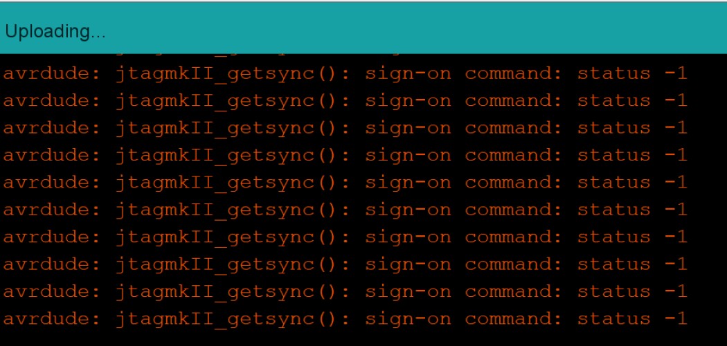
I rechecked all my connections and started troubleshooting. I started trying simpler codes that have worked a few days before. It only happened once, and unfortunately I did not get a photo, but at one point it stopped trying to upload and told me that “the selected serial port does not exist or your board is not connected.” I troubleshooted for a while with no avail. I moved on to programming the application part, I’m hoping to clear my head and come back to it later.
Processing Code
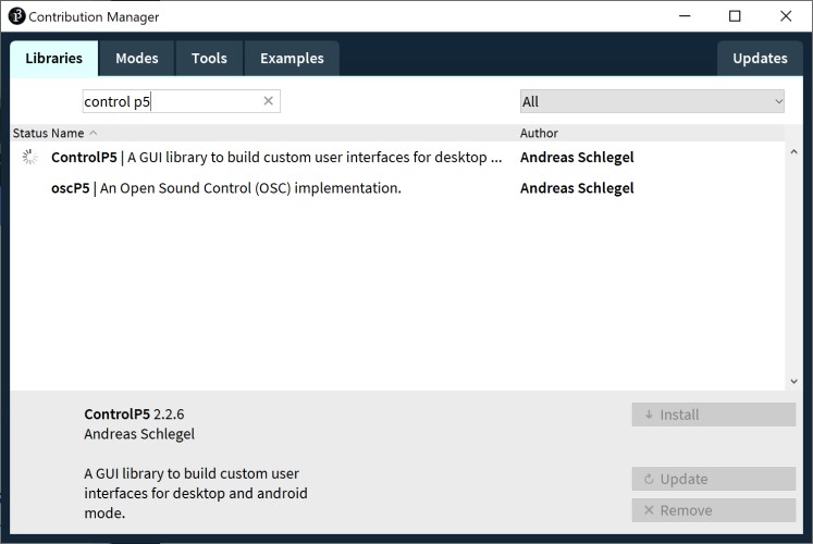
For my processing code, I wanted to make a simple slider that changes the RPM speed. After going through many forums, I found that a lot of people were using something called controlP5.* to create a slider. I decided I wanted to do this, so I imported that library and followed this tutorial to make it.
To import the control p5 library I went to Sketch -> Import Libraries -> Add Libraries then searched and Installed it. Serial was already installed.
I also imported processing.serial.*; so that processing would read the input values from the slider and communicate with my arduino code, which took the outputs. I used this site to figure out how to read the slider value. I also referenced this site for setting up values for serial communication, as well as some details to make the slider visually appealing. Finally, I referenced this site to learn how to send those values to arduino.
The hardest part was probably getting the slider to return a value that the Arduino could read, and making sure they were both the same datatype. Eventually I was able to fix that with these lines:
RPM = cp5.getController("slider").getValue(); //gets the value of the "slider"
RPM2 = int(RPM);    //makes the float RPM an int (arduino code uses int type)

port.write(RPM2); //writes to serial moniter

//note: port in setup is defined as this:
//port = new Serial(this, "COM7", 9600); // Set the com port and the baud rate according to the Arduino IDE
Processing Code:
import controlP5.*;
ControlP5 cp5;     //renames ControlP5 to cp5
import processing.serial.*;

ControlP5 controlP5;

Serial COM;
int speed= 0;

void setup()
{
  size(800, 800);

  COM = new Serial(this, "COM3", 9600); //assigns COM3 to "port" variable

  controlP5 = new ControlP5(this);
  controlP5.addSlider("speed")
    .setPosition(200,350) //sets slider's position
    .setSize(400,100)     //sets size
    .setRange(1000,2000);  //sets range of values of slider


  //, 1000, 2000, 0, 50, 125, 255, 12);
}

void draw()
{
  background(1000);
 // COM.write(speed); //writes value of "speed" slider
}
Arduino Code:
 #include <Servo.h>

Servo ESC;  // create ESC object to control a servo
// twelve servo objects can be created on most boards

int PulseRate = 1200;    // variable to store the BLDC pulse rate.
void setup() {
  ESC.attach(PIN_PA3, 1000, 2000);  // attach Signal pin to arduino pin 6, set minimum pulse width and maximyum pulse width in microseconds).
}

void loop() {

  if(Serial.available()){
     PulseRate = Serial.read();
     ESC.write(PulseRate);              // tell servo to go to position in variable 'pos'
     delay(500);                       // waits 1s
  }
}
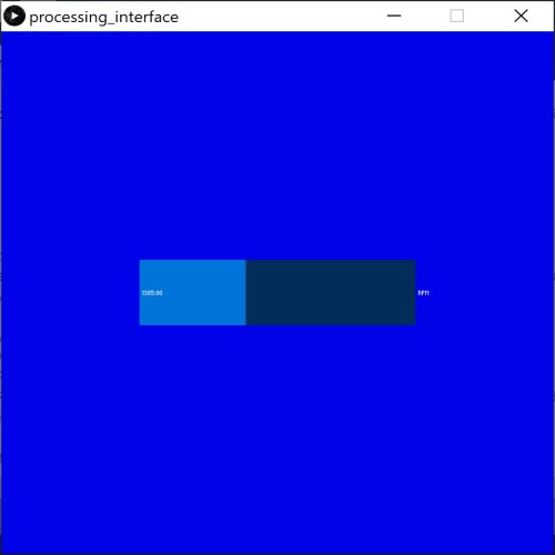
Photo of processing app:
Video: