Group assignment
We were 4 on the group assignment:
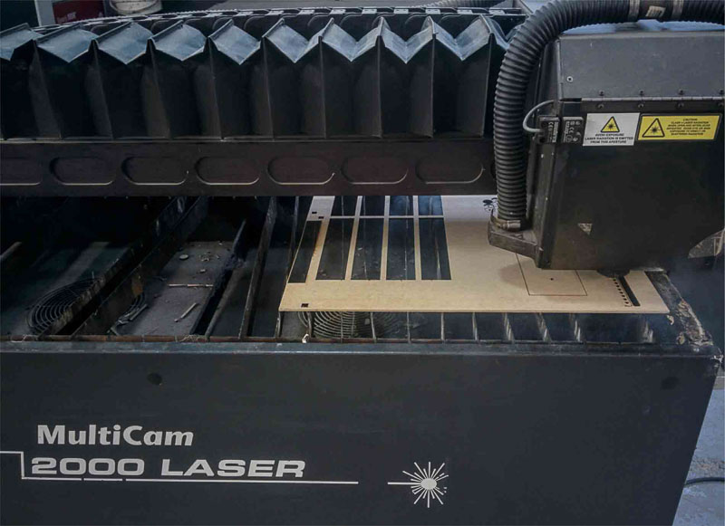
Our idea was to use one of the Trotec machines, either the 100 or the 400, but they were being used all morning by other students, so after waiting for a while we finally decided to do it on the old and huge Multicam 2000. Our instructor Mikel Llobera helped us throught the process. This would have been really impossible without him, given the complicated interface of the machine, not to mention that some parts of it are not working properly.
Our first step was to find a template that included different types of cuts, engravings and rasters all on the same piece. We found this one and opened it with Rhino, to prepare it.
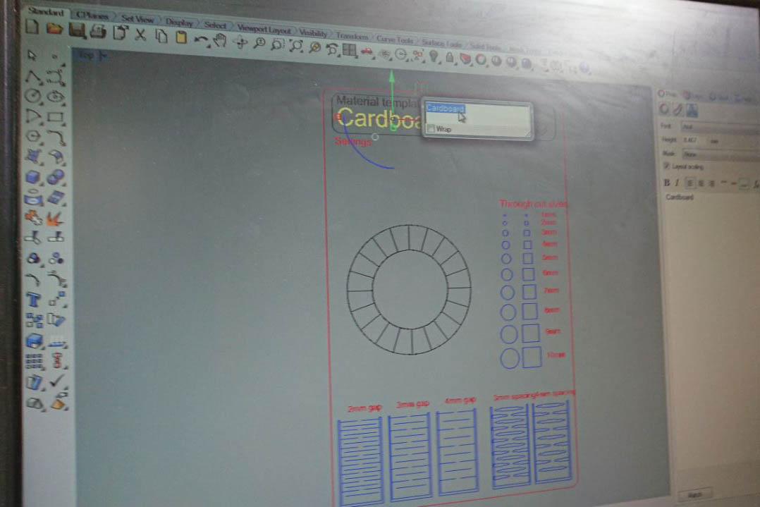
On the multicam, you have to go through it's own software called EnRoute, that turns a DXF file into gcode that the machine can read. With EnRoute open and connected to the machine, you can load the file from it's 1980's-style handheld interface, which is both cumbersome and amusing at the same time.
Once we had the piece on EnRoute, after a few crashes of the software due, we think, to the amount of different lines on the design, we learned that we would have issues with raster on that machine, so we had to remove the parts of the design that were supposed to be rastered (in this case, the classic wheel with strength percentages)
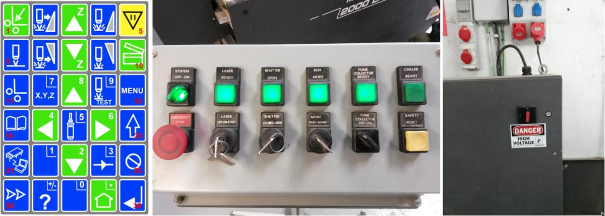
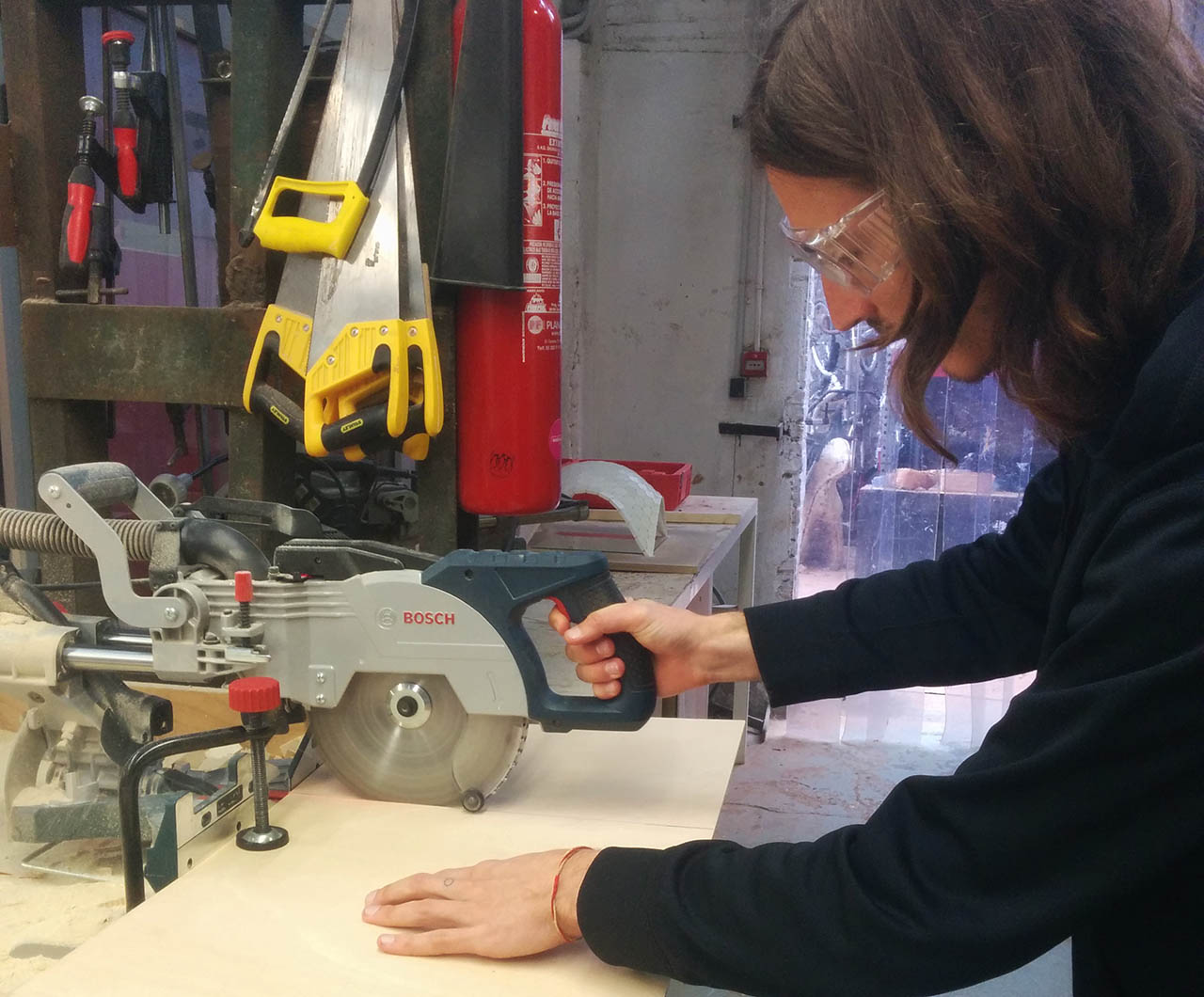
When the file was ready on EnRoute, it was time to prepare the multicam for cutting and engraving. The process we followed is more or less the following:
- Align material on one side of the bed.
- Set 'home' to one corner of your material.
- Configure jog speed - This is how fast the head moves when travelling.
- Set laser header distance to the material by moving the laser head down until the calibration piece touches the material.
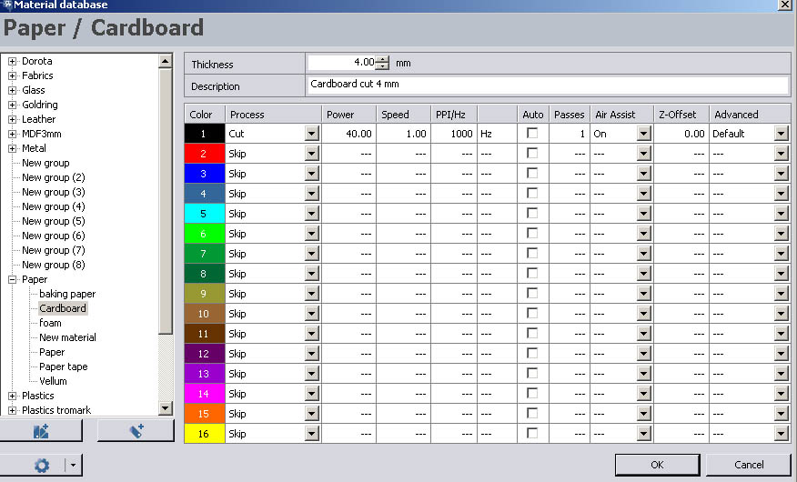
- Select material from material library. We chose cardboard
- Enter material thickness - in our case, 4mm
- Select cut mode (cut/engrave/raster)
- Select cut pressure - This is the amount of air blown into the material to prevent fires.
- Set the speed and power values: We started with 150/100 and it caught fire. So we lowered it to 100/100 to cut and then used 60/100 to engrave.
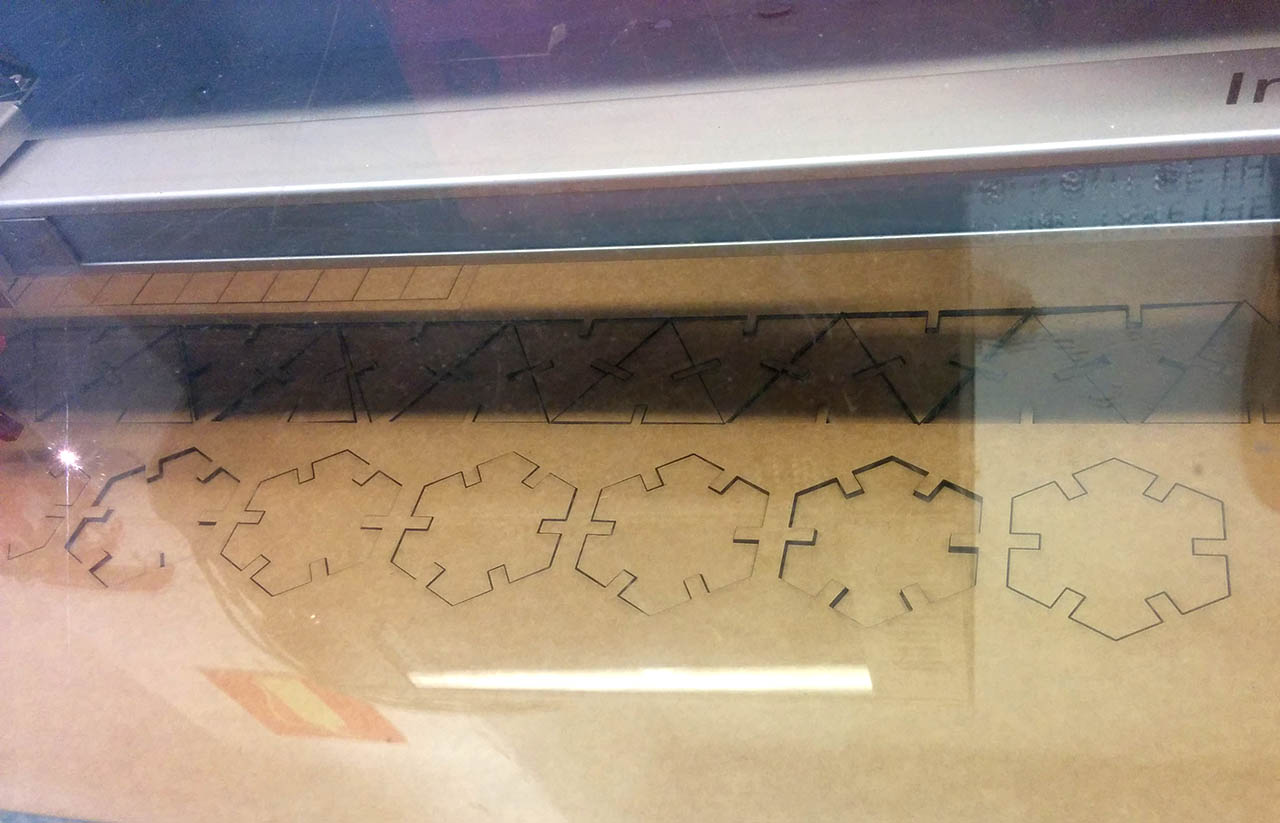
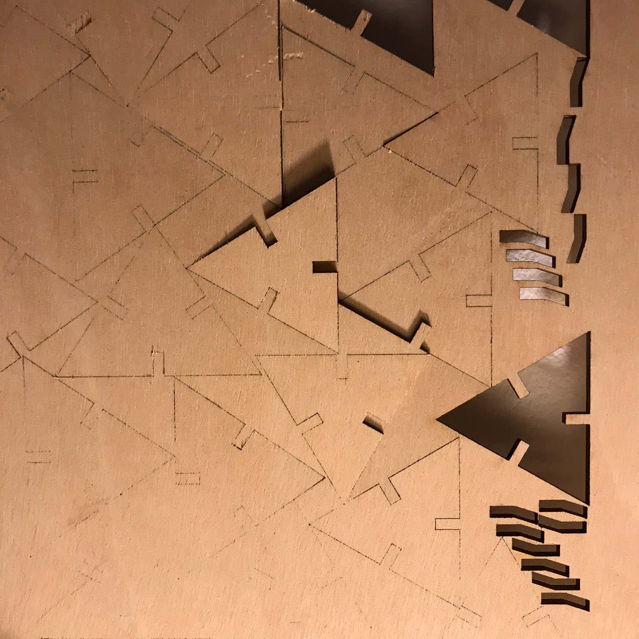
The result piece looked like this. Pretty good after all !
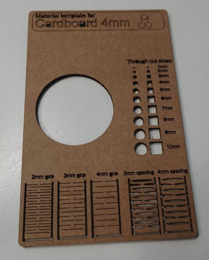
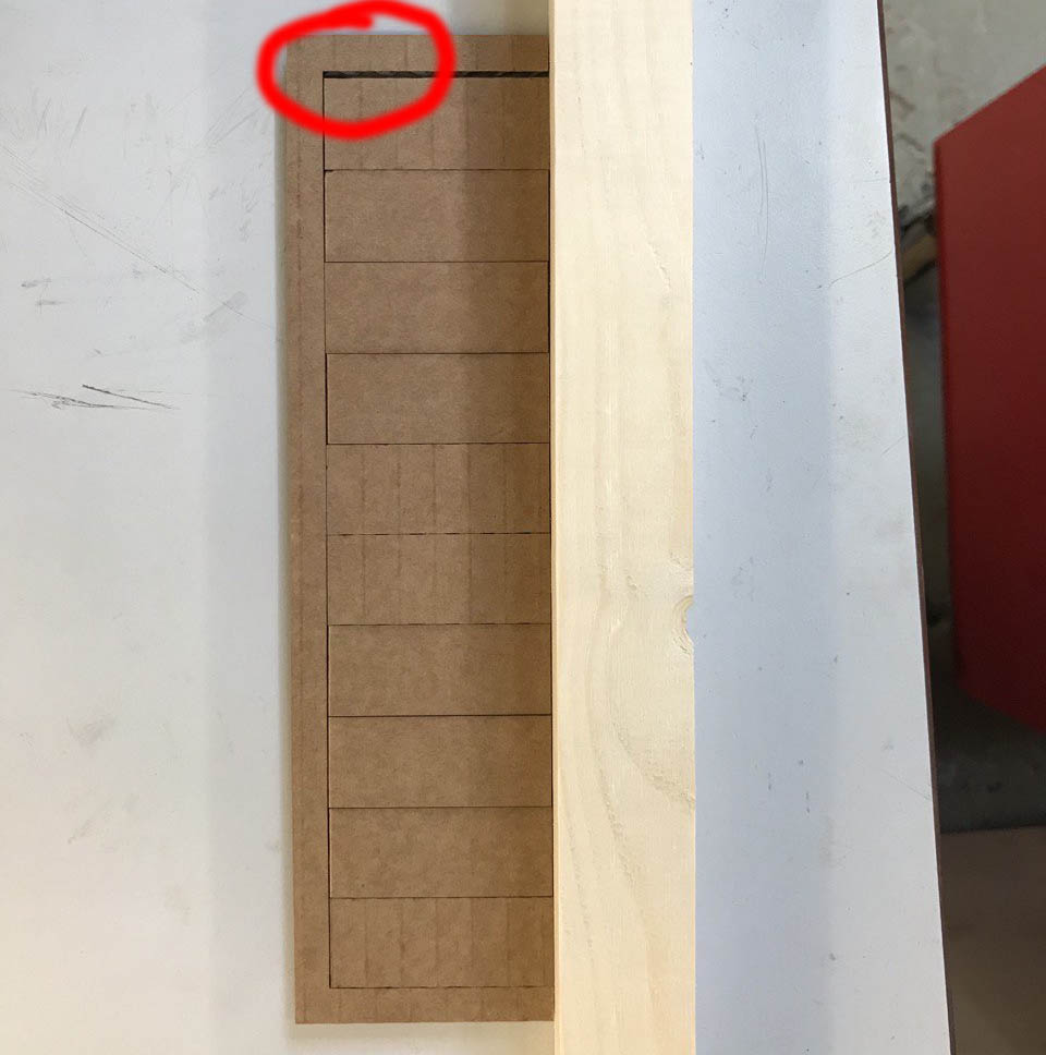
The last part was calculating the kerf, so what we did was design a piece with 10 cuts and cut it, press all the pieces together, measure the gap left on the edge, and divide it by the number of pieces. In our case, we got a kerf value of 0.15mm
Laser cutting
For the assignment, we had to create a construction kit using press fit parts while making the design of the pieces parametric, so that we could easily change their dimensions and settings. To do so i used Fusion 360, as i had already used it in last week's assignment and found the way to do parametric design very easy and convenient.
Because i didn't know how much time i would have to do this assignment, i decided to do something easy, a set of hexagonal pieces with press fit joints on each side.
I started by creating a simple hexagon shape on Fusion 360 with a press fit joint on one side, all parametrized: the radius of the polygon, the depth of the joint, and the width modified by the kerf value. I then created a circular pattern from the center, repeating this joint on all sides of the hexagon.
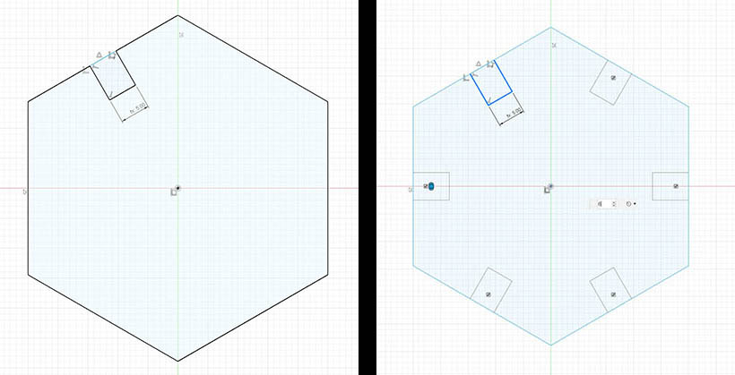
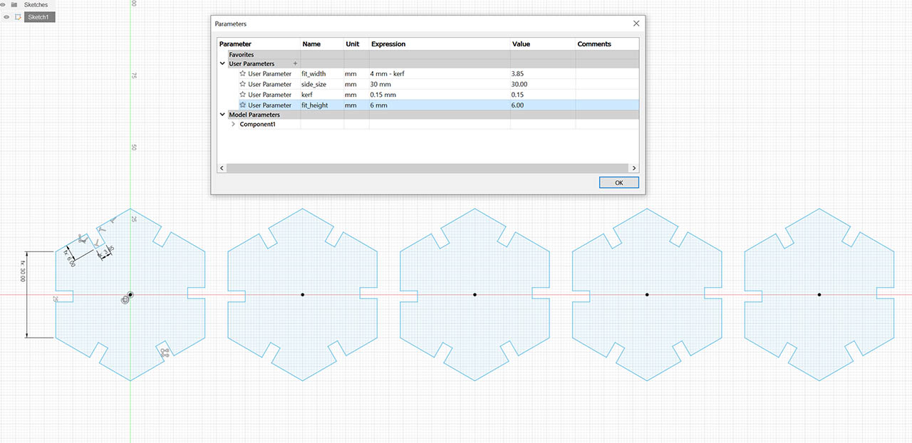
After deleting the outer side of the press fit joint, the piece is complete and parametrizable. Now we can just replicate the piece as many times as we want using the rectangular pattern tool on Fusion 360, and if we change a parameter from the change parameters menu, all the pieces will adapt to the new values. I made 8 pieces.
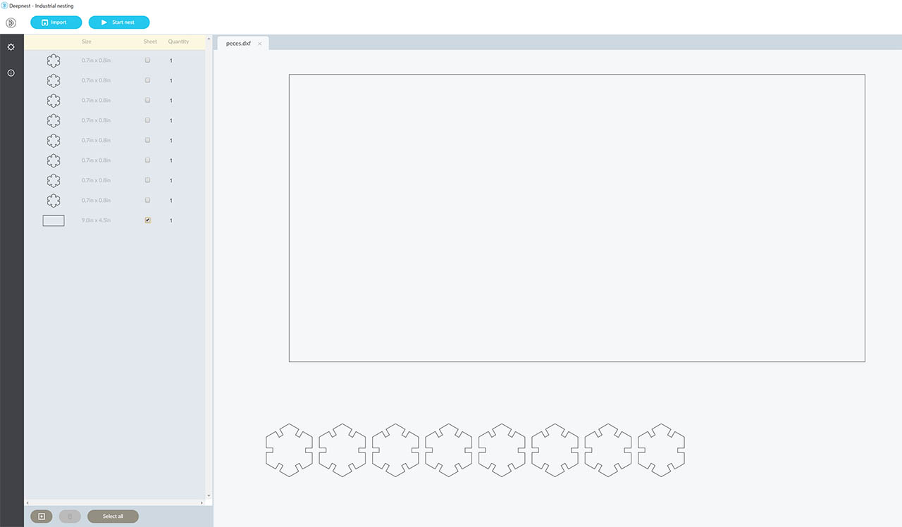
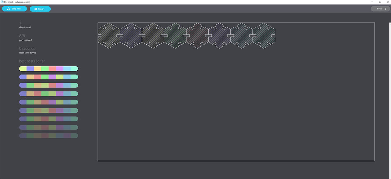
Before exporting the final .DXF, i wanted to try to use a nesting software to optimize the layering of the pieces on the material. Even though there is not much room for optimization with such a simple layout, i was interested to see how the software worked. For that, i downloaded an open source program that we saw on thursday's class, Deepnest. The results, even if the design was super simple, were pretty promising:
I finally went back to the sketch to account for the kerf value calculated during the group assignment, which in our case was 0.15mm. So i just changed the kerf parameter on my parametric design and all the pieces adapted to the new size of the press fit joint accordingly.
Now it was time to load the design into the cutting software and prepare the machine for the cutting. Since both laser cutters were pretty busy with all the students and it was hard to get a hold of one, we teamed up with Antoine Jaunard and decided to print both projects at the same time to save time (and materials!).
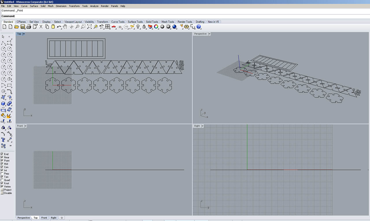
We started by laying out all the pieces on Rhino, which is the software that our machines use to talk to the laser cutter, and then entered the parameters on our guide sheet to cut 4mm cardboard, which in our case were P: 40, S:1, F:1000.
Once everything was ready, we calibrated the height of the laser head to have the focus of it on the material. You do this by using the small metal piece that comes with it for this purpose, where you literally hang it from the laser head, and then slowly raise the laser cutter bed until it touches the piece and makes it fall off. We couldn't help but laugh at having to do such a process on such an expensive machine :)
The next step was just to close the lid, hit the start button on the Trotec software, and stare in awe at such a wonderful process:
The first results were not great. Some of the pieces were left out of the cutting area, and we made a silly mistake by adding the kerf, instead of substracting it, which made the joints a bit loose. So we decided to cut again, after modifying the parameters on both designs, this time on plywood.
After cutting a chunk of plywood big enough for both sets, we reordered the layout to prevent some of the pieces to be left outside. We did this manually on rhino, although in hindsight, we could have run a deepnest with both sets, and i am sure it would have yielded great results.
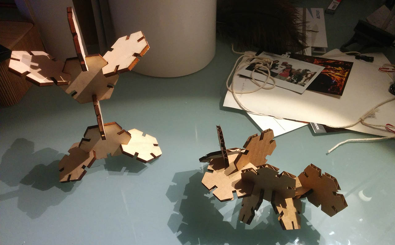
And this time we had another issue. First, we forgot to change the values from the cardboard ones, but luckily we realized soon enough after only one piece was engraved, so we changed it and re-ran it. Then, the plywood was bent, and even if we put some tape to hold it and straighten it, some of the pieces (sadly most of Antoine's, actually) were not entirely cut, since the laser was defocused at that height. I personally was able to salvage most of them, so i had my construction kit ready. Here's the back of the plywood with the shallow cuts, and the final constructions using the cardboard cut and the plywood cut:
Vinyl Cutting
The vinyl cutter is similar to the laser cutter, but instead of moving on a plane it just moves on a line, and has the medium (paper, vinyl..) move along, thus effectively moving on a plane. It also, obviously, has a sharp razor instead of a laser. I used the Roland GX-24. In barcelona we have a Cameo as well.
Here's some interesting specs of the Roland GX-24 machine:
- Loadable Material: from 50 to 700mm
- Maximum cutting area: 584mm x 25000mm
- Maximum cutting speed: 500 mm/s
- Maximum cutting thickness: 1mm
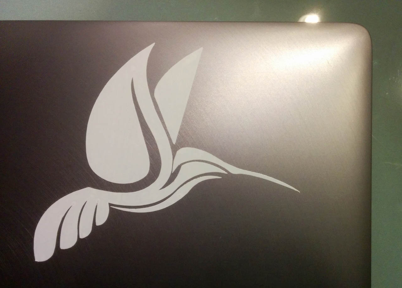
I chose to make a humming bird. For that, browsed through the pages of Vecteezy and found one that i really liked Here by Taswin Tariban.

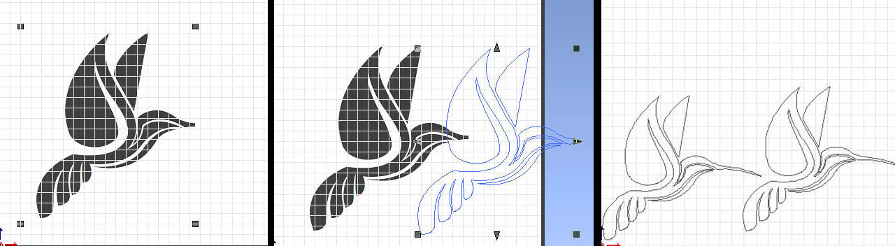
I first turned the hummingbird from .eps to .jpg, thinking that the vinyl cutter onky accepted images. But then found out that it can actually import images, but it prefers vectors. So if you inmport an image, you have to turn it into a vector from the software itself. in these 3 images you can see the shape imported, the outline version and finally i duplicated and scaled the outline to fit 2 birds in the width of the vinyl i had.
Before starting to cut, i loaded a roll of vinyl, set the distance between the wheels to the edges of the vinyl, making sure they stayed within the white marks on the machine, and made sure the razor was at an appropiate height.
I corroborated that by printing a test pattern, which in the Roland machine is a small square cut with a circle cut inside, and it all seemed to go well. So i loaded the outlines and ran the cut. It came out well, although not perfect. I could see that the head had run over some cuts, lifting them. There are probably 2 causes for this:
- The outline that the cutting software created from the image had some lines VERY close to each other. Much more so than the origin vector file.
- The speed of the cut was probably too high
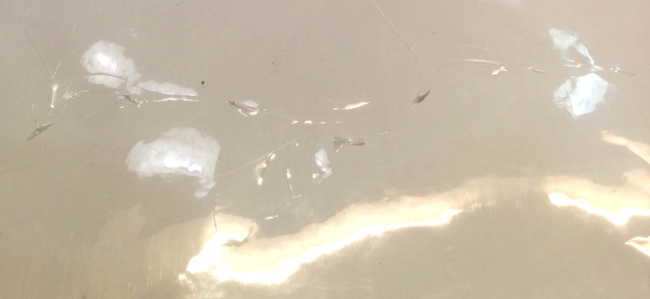
Even so, being careful and with some thin tweezers, i was able to get the cut parts out of the vinyl perfectly, and i managed to stick it on my laptop.
The Files
- Kerf measurement tool: Kerf DXF
- Press fit construction kit: Fusion 360
- Press fit construction kit: DXF
- The vinyl cutter vector file, as stated before, can be found here (i do not own it)