ASSIGNMENT
Read a datasheet and program your board to do something.
THE DATASHEET
I chose to read the ESP32-WROOM-32 datasheet located here. At first sight it felt to me that it was really short (25 pages) compared to the ones Neil was showing on wednesday's class (~400). Then i saw that this was more like an extension to the parent ESP32 board datasheet which is bigger but not that much. In any case, i found some interesting things in there.
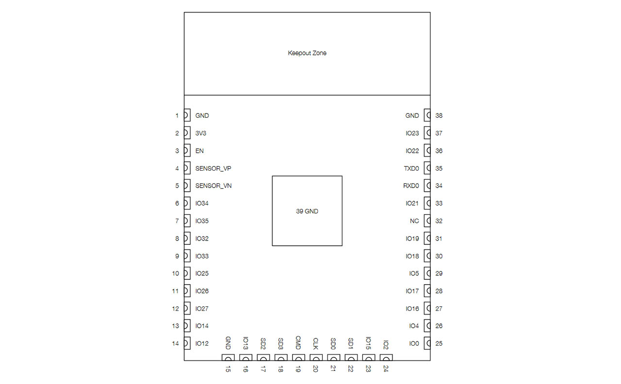
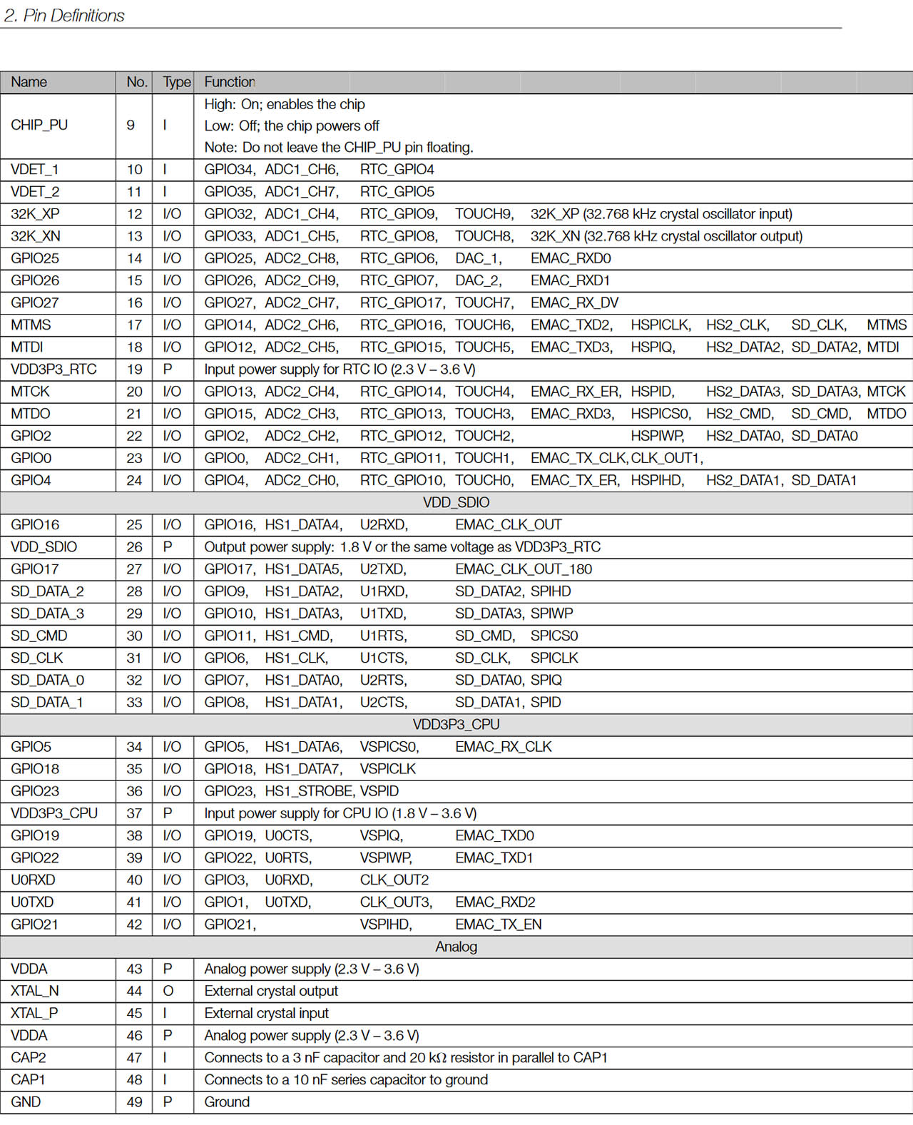
I started by looking at the pin layout, to see which pins i could use to try to program something using them, and found a handy diagram, and a complicated table with descriptions of all of them. The correspondence of pin labels and what they mean can be found in the peripherals and sensors section of the datasheet.
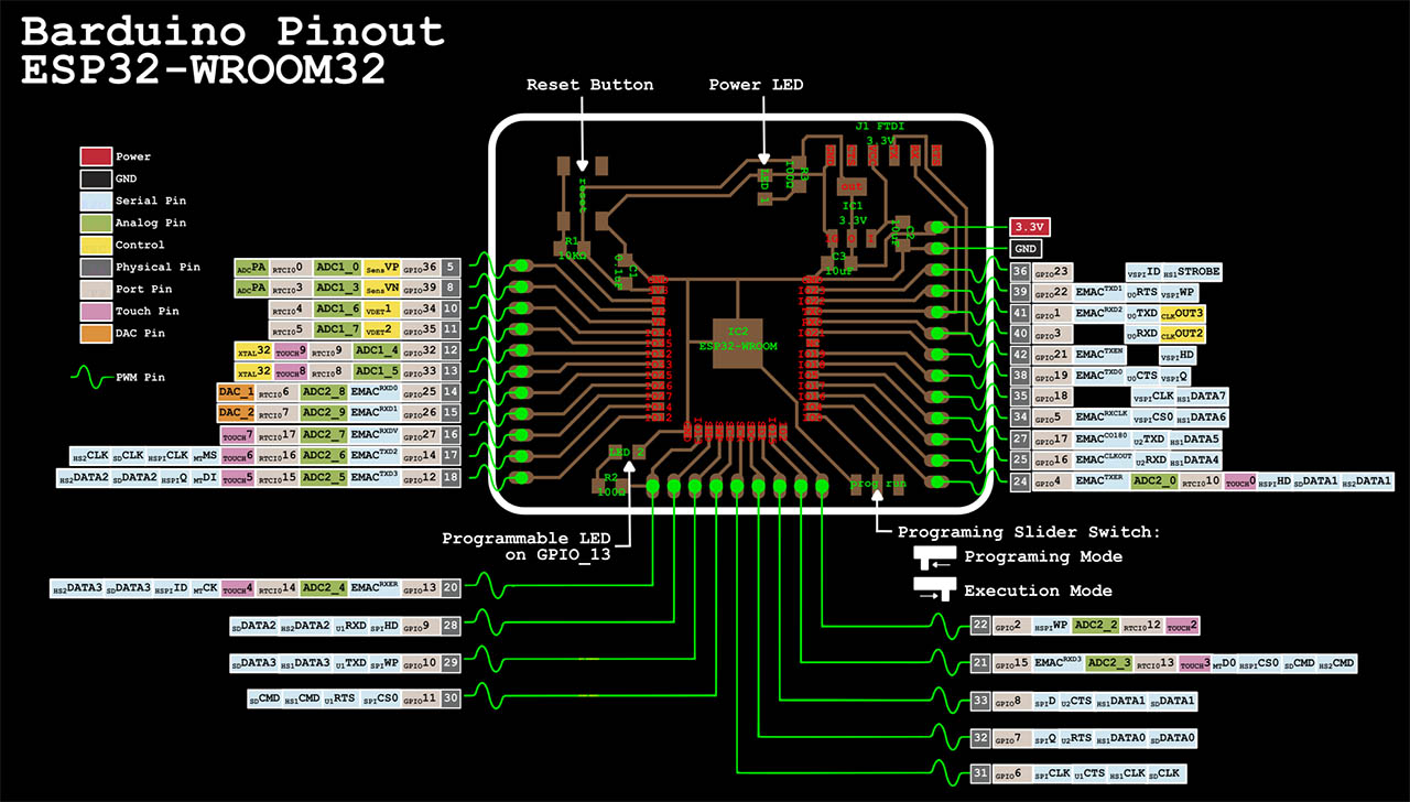
Then i found this image on the Barduino page (more on this below) that grouped the two things together and made things a bit more clear:
I found other parts that were interesting to know, like the one about memory:
- 448 KB of ROM for booting and core functions
- 520 KB of on-chip SRAM for data and instructions
- 8 KB of SRAM in RTC, which is called RTC FAST Memory and can be used for data storage; it is accessedby the main CPU during RTC Boot from the Deep-sleep mode.
- 8 KB of SRAM in RTC, which is called RTC SLOW Memory and can be accessed by the co-processor duringthe Deep-sleep mode.
- 1 Kbit of eFuse: 256 bits are used for the system (MAC address and chip configuration) and the remaining768 bits are reserved for customer applications, including flash-encryption and chip-ID.
- Embedded flash
It was also cool to learn that the ESP32 can have up to 16 MB of external flash can be mapped into CPU instruction memory space and read-only memoryspace simultaneously.
Other interesting things to know where the WIFI radio details: ESP32 implements a TCP/IP and full 802.11 b/g/n Wi-Fi MAC protocol. It supports the Basic Service Set (BSS)STA and SoftAP operations under the Distributed Control Function (DCF). Power management is handled withminimal host interaction to minimize the active-duty period.
It was also great to know that it supports bluetooth 4.2: The Bluetooth stack of the chip is compliant with the Bluetooth v4.2 BR / EDR and Bluetooth LE specifications
Also fascinating was to read about the power management options, i never imagined that. This is truly a computer on it's own.
- Active mode: The chip radio is powered on. The chip can receive, transmit, or listen
- Modem-sleep mode: The CPU is operational and the clock is configurable. The Wi-Fi/Bluetooth base-band and radio are disabled.
- Light-sleep mode: The CPU is paused. The RTC memory and RTC peripherals, as well as the ULPco-processor are running. Any wake-up events (MAC, host, RTC timer, or external interrupts) will wakeup the chip.
- Deep-sleep mode: Only the RTC memory and RTC peripherals are powered on. Wi-Fi and Bluetoothconnection data are stored in the RTC memory. The ULP co-processor is functional.
- Hibernationmode: The internal 8-MHz oscillator and ULP co-processor are disabled. The RTC recoverymemory is powered down. Only one RTC timer on the slow clock and certain RTC GPIOs are active.The RTC timer or the RTC GPIOs can wake up the chip from the Hibernation mode.
When reading the details on the peripherals section, where the pin types are detailed, a few things caught my eye as well:
- Touch Sensor - ESP32 has 10 capacitive-sensing GPIOs, which detect variations induced by touching or approaching the GPIOswith a finger or other objects.
- Two Digital to Analog converters and one Analog to digital converter.
- Infrared remote controller - The infrared remote controller supports eight channels of infrared remote transmission and receiving.
- Cryptographic hardware acceleration - ESP32 is equipped with hardware accelerators of general algorithms, such as AES (FIPS PUB 197), SHA (FIPSPUB 180-4), RSA, and ECC, which support independent arithmetic, such as Big Integer Multiplication and BigInteger Modular Multiplication
Lastly, it was very interesting to know that the board can operate on a range of -40 to 150 degrees, which seems to me like an insane range !
PROGRAMMING
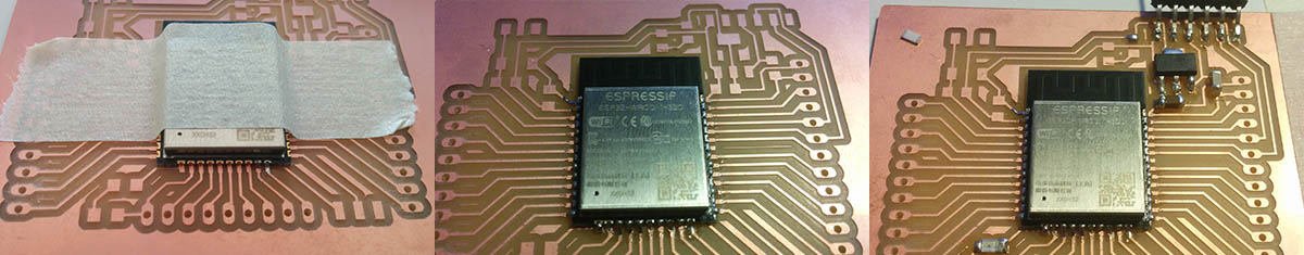
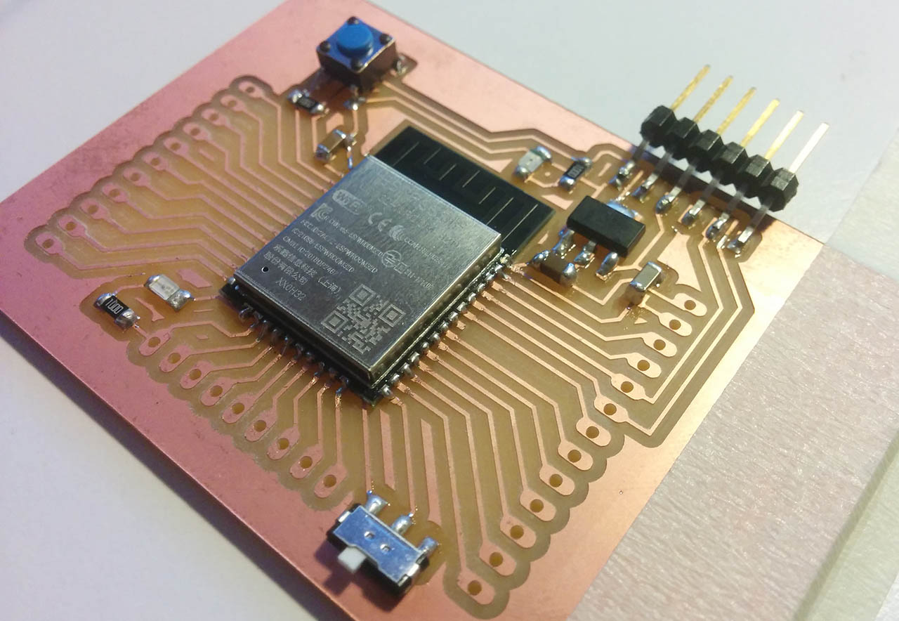
For this assignment I soldered a new board using the ESP32 to be able to use WIFI for my final project. The soldering process went really smooth compared to other weeks. Maybe I actually learned something ! The design i chose was the Barduino 2.0 based on Neil's ESP32 board, redesigned by our instructors Eduardo Chamorro, Josep Marti and Oscar Gonzalez.
The board has an FTDI serial connector, a power LED and a built-in LED for testing, along with a reset switch button and a slide switch to select the mode (Programming or Executing).
Before connecting the board to the PC, i had to download into Arduino the ESP32 libraries. To do so you just go into File > Preferences and click on Additional Boards Manager URLs. The instructors in Barcelona provided us with a list of URLs with the most common libraries, including the one for the ESP32. So after loading the library I just had to choose the ESP32 board. After connecting the board to the PC using an FTDI to USB cable, i chose the port it was connected to, in my case COM3 and then I started by trying the classic blink example on the board using the Arduino IDE and the built-in LED. Luckily everything worked wonderfully :)
I then picked up some components and a breadboard to try out some of the extra pins of the ESP32. I decided to create just a simple LED sequence by alternating 3 of the board pins with GPIO names 12, 14 and 27. The code drives current through one of the pins, waits for 100ms and then stops drawing current, alternating the 3 pins in pairs. I placed a resistor for each of the LEDS and made sure to connect the ground from the board to the ground line on the bread board as well. The code is still super simple:
          #define LED1 12

          #define LED2 14

          #define LED3 27


          // the setup function runs once when you press reset or power the board

          void setup() {

            // initialize digital pin LED_BUILTIN as an output.

            pinMode(LED1, OUTPUT);

            pinMode(LED2, OUTPUT);

            pinMode(LED3, OUTPUT);

            pinMode(13, OUTPUT);

          }


          // the loop function runs over and over again forever

          void loop() {

            digitalWrite(13, HIGH);

            digitalWrite(LED3, LOW);

            digitalWrite(LED1, HIGH);

            delay(100);

            digitalWrite(LED1, LOW);

            digitalWrite(LED2, HIGH);

            delay(100);

            digitalWrite(LED2, LOW);

            digitalWrite(LED3, HIGH);

            digitalWrite(13, LOW);

            delay(100);

          }
Next I tried to drive an LED strip i had using adafruit's Neopixel Library, but after trying many configurations, i think the strip may be broken, since i remember doing some tests with a friend with an arduino and that library back in the day. This was supposed to be sending pulses of light along the strip, and it clearly is not.
Finally I went on to do something useful for my Final project.
OSC is a communication protocol that many libraries and programs support. In a nutshell, it (often) uses UDP packages to send and receive information, organized in hierarchichal messages. The most simple example of an OSC formatted message would be: "/message/Hello"
I wanted to test the wifi capabilities of the board, because i need to use this for my final project, so I looked for an OSC over WIFI library for the ESP32 and found this by Hideaki Tai curiously a member of Rhizomatiks, an interactive arts studio that i like very much. The library is very easy to use. You can:
Connect to wifi and setup OSC with 3 lines of code:
        WiFi.begin("[wifi-name]", "[password]");

        WiFi.config(IPAddress(10,0,0,20), IPAddress(10,0,0,1), IPAddress(255,255,255,0));

        osc.begin(8500);
Where the first two parameters are the name and password of your wifi network, the second line has:
- The IP you want your board to have (make sure no other devices are using it!)
- The gateway
- The subnet mask
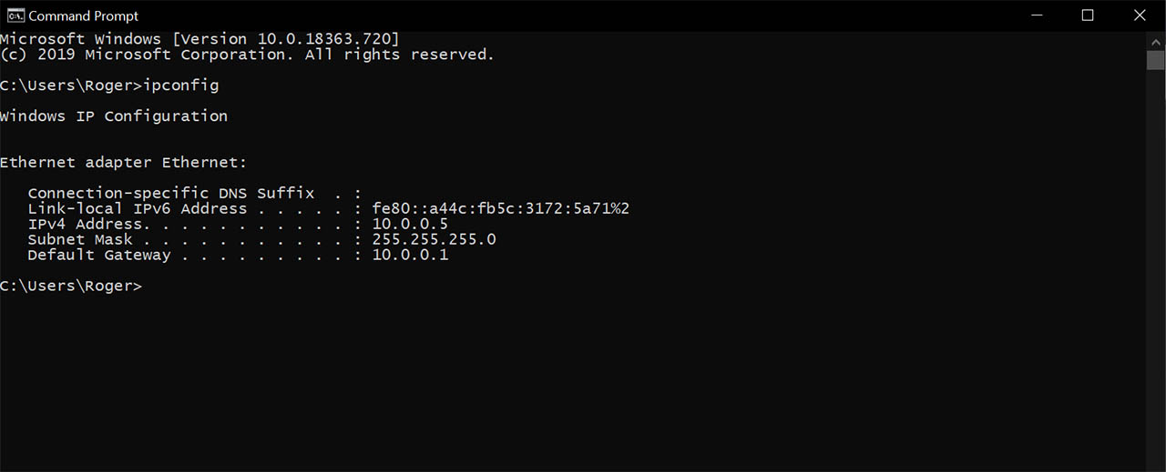
If you are confused about gateway and subnet mask, just type ipconfig on the windows console and copy the value from there. This should work on most circumstances:
Send OSC messages with one line:
osc.send(host, send_port, "/send", 1, 2.2F, 3.3, "string");
Where:
- Host - is the ip address you want to send the osc packet to
- Port - the port where you want to send it to
- Label (/send in the example) - is the OSC label or address you're sending
- Message - just a list of content you want to send with it
And receive with 3 lines by writing this callback:
osc.subscribe("/lambda", [](OscMessage& m)
{
Serial.print(m.arg
});
Where the first parameter is the OSC label you're listening for, and the second an array of the contents it came with. Inside the callback, you'd do anything you want with the contents of the OSC packet. In this case we're just printing the value we get to the serial monitor.
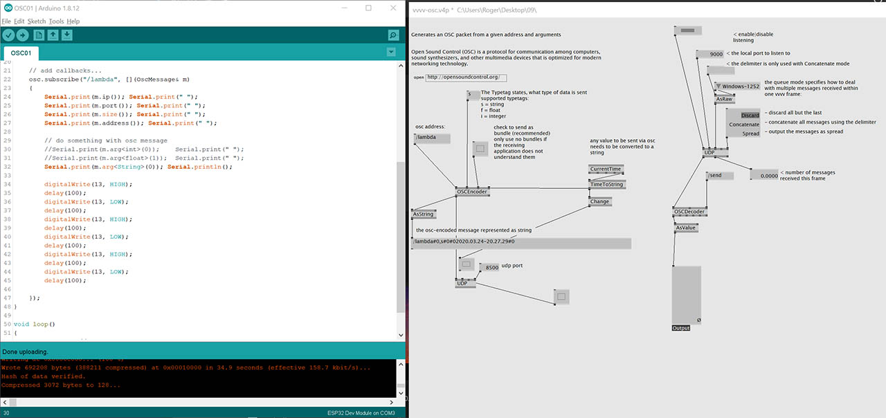
So the next step to try this code was to find a way to both send and receive OSC messages over WIFI via UDP packets. For this, i chose vvvv, a visual live programming environment that allows one to quicly prototype audio visual stuff with easy communication pathways. It is kind of a multimedia version of mods if you will.
The idea is not to use vvvv (for now) but to maybe build an interface in Unity for tablets that sends OSC messages to the light sculpture to control it's behaviour. At the same time, ideally, a MIDI keyboard could also be connected directly to the board ( i have seen MIDI I/O libraries for the arduino ) or alternatively the MIDI signals could be converted to OSC and then sent to the board to alter the light sequences.
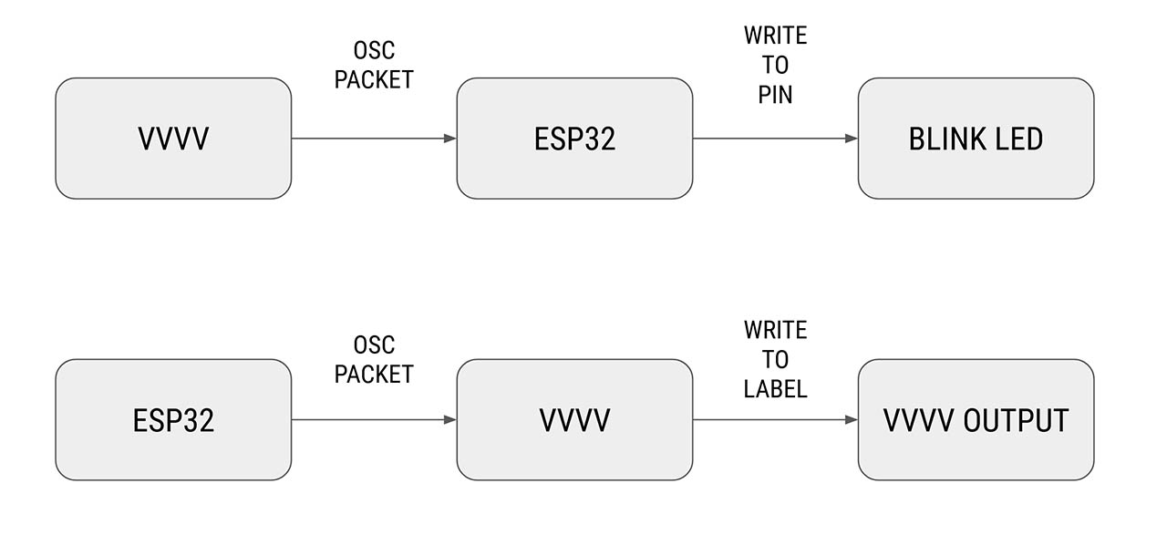
The diagram of this first experiment setup could be laid out like this. vvvv sending OSC packets to the board and the board lighting up an LED, while at the same time the board will send OSC packets to vvvv which will just capture them and print them out.
So once i had the OSC code on the ESP32 side, and the vvvv patch up and running, both sending OSC packets and waiting to receive some, i loaded the board with the code, but was only getting packets, and not getting any indication that the board was receiving the ones being sent from vvvv.
After much debugging i turned on the serial monitor and saw that it was actually crashing shortly after sending the first message and then immediately rebooting and going on this loop of reboot, send osc, crash, reboot... I love the error message "Guru meditation Error" But no idea what it means.
19:33:25.701 -> Rebooting...

        19:33:25.701 -> ets Jun  8 2016 00:22:57

        19:33:25.701 ->

        19:33:25.701 -> rst:0xc (SW_CPU_RESET),boot:0x13 (SPI_FAST_FLASH_BOOT)

        19:33:25.701 -> configsip: 0, SPIWP:0xee

        19:33:25.701 -> clk_drv:0x00,q_drv:0x00,d_drv:0x00,cs0_drv:0x00,hd_drv:0x00,wp_drv:0x00

        19:33:25.701 -> mode:DIO, clock div:1

        19:33:25.701 -> load:0x3fff0018,len:4

        19:33:25.701 -> load:0x3fff001c,len:1216

        19:33:25.701 -> ho 0 tail 12 room 4

        19:33:25.701 -> load:0x40078000,len:9720

        19:33:25.701 -> ho 0 tail 12 room 4

        19:33:25.701 -> load:0x40080400,len:6352

        19:33:25.701 -> entry 0x400806b8

        19:33:25.940 -> HOLA

        19:33:26.519 -> .0 Guru Meditation Error: Core  1 panic'ed (LoadProhibited). Exception was unhandled.

        19:33:28.597 -> Core 1 register dump:

        19:33:28.597 -> PC      : 0x400d100d  PS      : 0x00060830  A0      : 0x800d25a8  A1      : 0x3ffb1e80

        19:33:28.597 -> A2      : 0x3ffc1364  A3      : 0x3ffcbc90  A4      : 0x3ffc1520  A5      : 0x3f408fcb

        19:33:28.597 -> A6      : 0x3ffb1e8c  A7      : 0x00000000  A8      : 0x00000004  A9      : 0x00000000

        19:33:28.597 -> A10     : 0x00000003  A11     : 0x00000001  A12     : 0x3ffbd960  A13     : 0x3ffc1520

        19:33:28.597 -> A14     : 0x3ffcbc90  A15     : 0x00000001  SAR     : 0x00000010  EXCCAUSE: 0x0000001c

        19:33:28.597 -> EXCVADDR: 0x00000003  LBEG    : 0x400d100d  LEND    : 0x400d101b  LCOUNT  : 0x00000003

        19:33:28.597 ->

        19:33:28.597 -> Backtrace: 0x400d100d:0x3ffb1e80 0x400d25a5:0x3ffb1ec0 0x400d25ef:0x3ffb1f00 0x400d4245:0x3ffb1fb0 0x40088b7d:0x3ffb1fd0

        19:33:28.597 ->

        19:33:28.597 -> Rebooting...
After a bit of debugging and commenting parts of the code i realized the board was crashing when receiving OSC messages. And i realized what was happening: I had just left the default example message parsing, which was expecting 3 different values, but i was only sending one from vvvv, and thus the crash and reboot while trying to access an empty memory address. After changing the osc callback to only parse one message (the one i was sending from vvvv) I was now getting the correct value:
          19:48:52.929 -> HOLA

          19:48:53.506 -> .10.0.0.5 62822 1 /lambda 2020.03.24-19.49.04
Now that the whole flow of information is working, i just changed the code to be a bit more friendly. From the vvvv side i would send two messages from the OSC address /toboard: Either "Hello Board!" or "How are you?", depending on what box is connected to the OSC sender. The messages will be sent when i press the (virtual) button on vvvv.
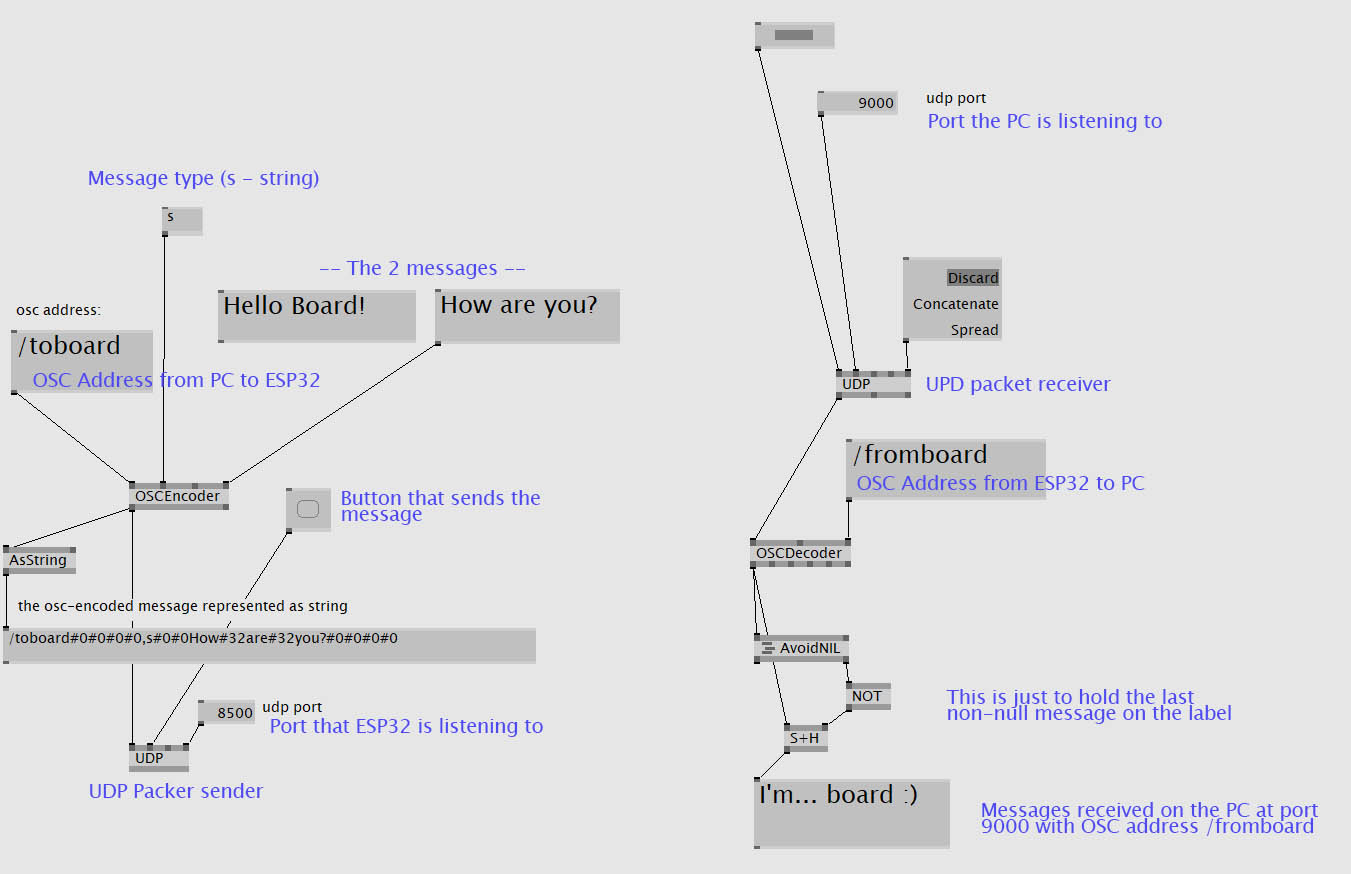
From the ESP32 side, i would listen to messages coming in with the OSC address /toboard. Flash the builtin LED for a second when getting one, and then parsing the content and sending a reply with the OSC address /fromboard, like this:
osc.subscribe("/toboard", [](OscMessage& m)
{
digitalWrite(13, HIGH);
delay(1000);
digitalWrite(13, LOW);
if( m.arg
{
osc.send("10.0.0.5", 9000, "/fromboard", "Hi there"); // send osc packet in one line
}
else if( m.arg
{
osc.send("10.0.0.5", 9000, "/fromboard", "I'm... board :)"); // send osc packet in one line
}
});
And here's a video of the whole functioning ESP32-PC OSC over WIFI communication:
THE FILES