Group Assignment
I did the group assignment with my fellow students:
For this week's group assignement, we picked a test file from Thingiverse in order to test different features of one of the 3D printers we have in Fab Lab Barcelona, the Creality3D CR-10 S5 3D.
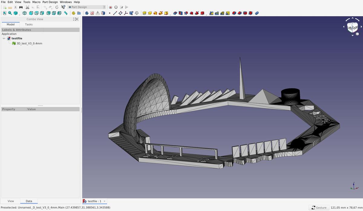
This file allows us to test these features:
- z-height check
- warp check
- spike
- hole in wall
- raft test
- overhang Steps 50° - 70°
- 2 different extrusion widths: 0.48mm & 0.4mm
To be able to print a 3D model, we have to send instructions to the printer, wich are written in g-code and tells the motors where to move. To prepare the g-code, we have to slice our 3D model (.STL), to simulate and anticipate how the model will be printed, according to the printer settings and gravity law.

At Fab Lab Barcelona, a computer with Ultimaker Cura is attached to the machines, with all the presets of the differents printers saved in it. It's therefore easier to directly use it in order to slice our model instead of searching the presets and install them on our personal laptop.
The filament we use is a PLA 1.75mm. It's a plant-based material made from starches like soybeans or corn. It needs to be heated at 190-200C° to be used.
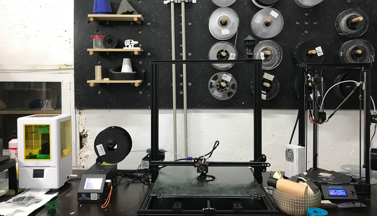
The printing was done in ~90 minutes without any troubles.
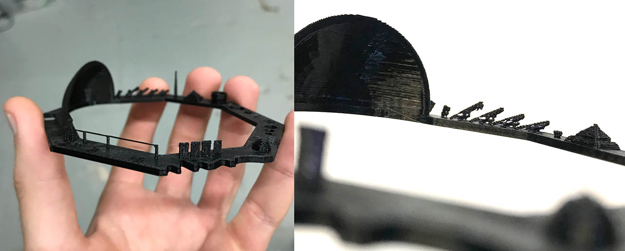
As we can see in the images above, the definition of the print is quite good, the details are respected and the print angles can be large (in fact more than 45°). Even the small bridges without support were printed correctly. I am very satisfied with this test and the new possibilities that it lets us see.
3D Scanning
The week's assignment for 3D Scanning was to scan an object and get the 3d mesh. During the local lesson we learned how to use Skanect, an open source 3D scanning software that uses Microsoft's Kinect 1, a now discontinued camera with IR and depth sensors initially released for the XBOX 360. As a matter of fact, the Kinect 2, bigger and better, released for the XBOX One, is also discontinued. Microsoft has a development kit of the next iteration of the series, the Azure Kinect, which works under the Microsoft Azure umbrella and offers cloud computing capabilities. This time though, the sensor is for research only and does not have a console version.
Skanect works essentially by grabbing the kinect and orbiting it around the object you want to scan while the kinect captures depth data from the scene, trying to cover all the angles. You can see a live representation of what's being scanned on the interface. The meshes it produces often need rework afterwards and are not super high-quality.
[img skanect interface]
On a previous class, our instructor Eduardo Chamorro showed us how you could create robotic arm motions from Grasshopper in Rhino. In short:
- You create the model of your robot with all the rotation axis.
- You create a curve in front of it ( or even around, if the model allows ) that will determine where the head of the robotic arm ( where the tool is ) will go.
- You create a polyline from the curve, and configure an acceptable density of points the robot will travel to
- You export the whole motion into an intermediate format that can then be translated into the different robot brands formats
Since fablab barcelona is located inside IAAC, we sometimes can access other types of machines, like a Kuka robot
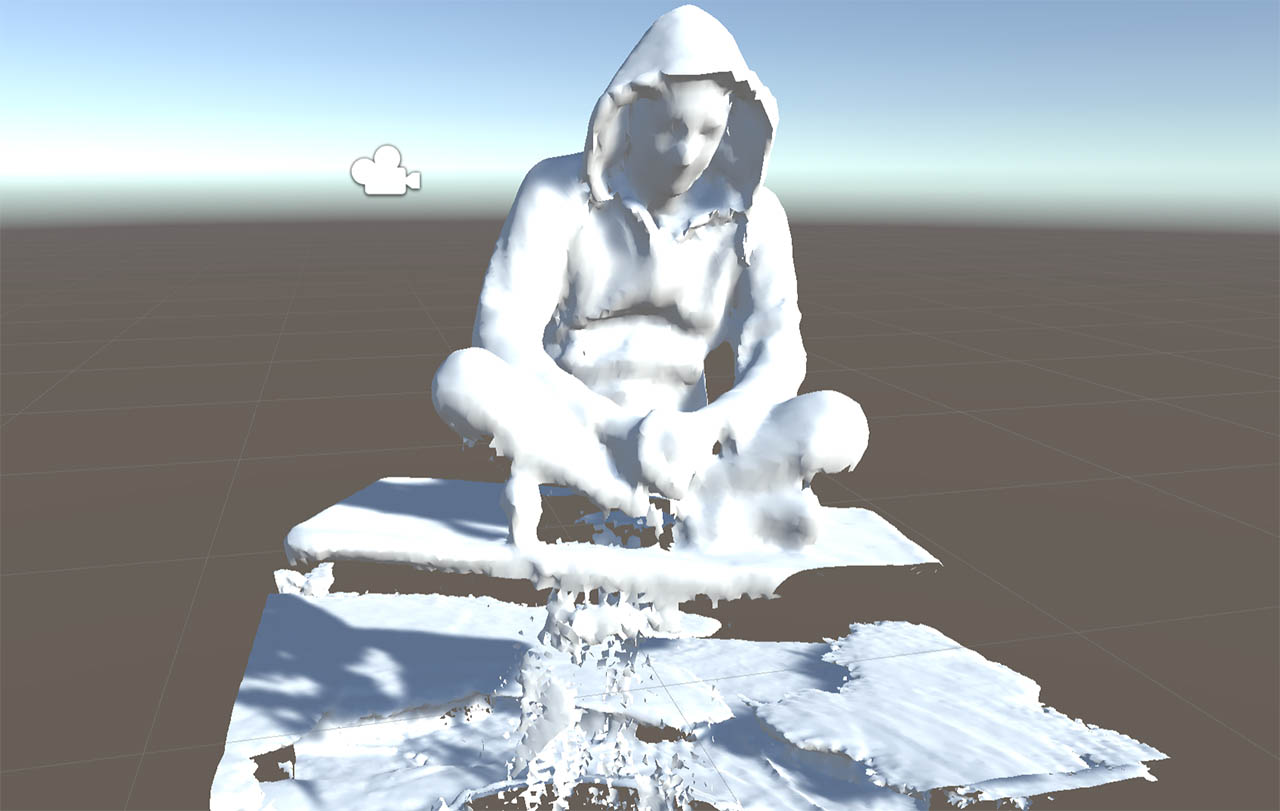
So, putting the two ideas together, 1) having to orbit a kinect around an object, and 2) having a Kuka robot in the house, we decided to have the robot scan us. So a small group of us, went on with Eduardo to set up and attach the kinect into the Kuka's head so that it would scan us. Eduardo had designed an orbiting trajectori around a rotating platform, so that Kuka would capture video with the Kinect from every angle before the rotating platform would rotate around 30 degrees, and the Kuka would repeat the process, thus getting many, vibration-free shots. Needless to say, it was us who stood on the platform :) This video summarizes the process really well:
Here's the mesh that came out of it where i seem to come out of the water on a hoverboard. To be honest, the detail as you can see is not great. That is probably because the kinect1 sensor is not that great. I wonder how it would look if skanect worked with the kinect 2 or the newest azure!
Now naturally i wanted to print it, and i will at some point, but i knew i wouldn't have time during the week given the necessary editions i had to make to it before sending it to the slicer. To visualize it i put it into Unity, which i know well.
On Friday's local class, Eduardo told us about Photogrammetry. The process to extracting reliable, high-quality 3D info and texture from a set of multiple pictures via image processing. We saw many examples with pictures captured from drones for instance.
I remember reading about it a few years ago and trying to follow a tutorial, but it was insanely difficult to get anything reasonable and the process was tedious and long. I was astonished to see how the field has evolved both in terms of ease and processing speed, mainly due to the use of CUDA gpus.
We saw 3 software packages:
- Agisoft Metashape - Very powerful, but also very expensive
- Adobe ReCap - Free for students but cloud-based
- Meshroom - Open Source and pretty good
I decided to use Meshroom to try to scan my kitchen/living room. I went on with my Canon EOS 60D to try to capture good quality pictures and stood in the middle of the room while taking 350+ pictures all around me and with different orientations.
Then dragged all the images into meshroom, and click start, leaving all the default settings on. Meshroom has a graph editor where you can see al the nodes and plug inputs to outputs as you please. But the default values are supposed to already give you a decent result. So all in all it's just drag the pictures, click start and wait.
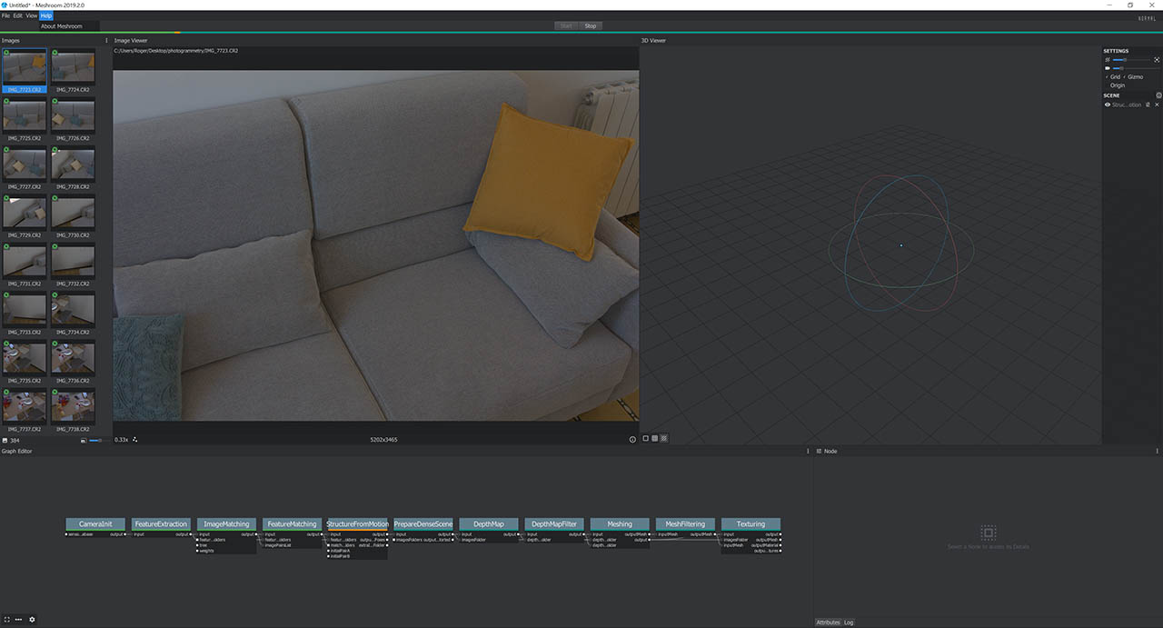
It is, however, a very resource intensive process, mainly for the CPU. I was expecting more GPU use, but i mainly saw the CPU being used close to 100% all the time. I read some documentation and issue posts on the github page and saw that there is work being done into improving and extending the CUDA functionalities to speed up the main processes.
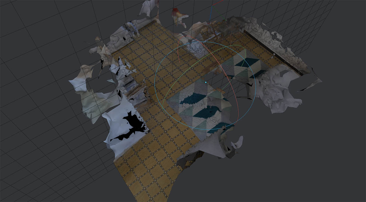
Finally, after going through all the nodes, i could see the resulting texturized mesh. And sadly it didn't work really well. I ended up for some reason with only the tile floor and the carpet being properly scanned, and both the couch and a desk were just hints of blobs around them.
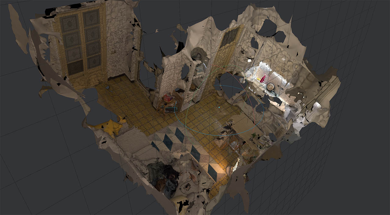
So i decided to try again. This time i took 590 pictures from several locations around the room, and in different orientations. In fact, i took too many, since meshroom then told me it would only use 366 of them. I also made sure the lighting was more consistent ( i took this new set at night, the other during the day ).
The result was definitely better! But still far from perfect. The resulting mesh had north of 2 million faces, so i opened it in Blender to optimize it a bit. I went through these 2 steps:
Remove close vertices:With your object selected, by going into edit mode (clicking TAB key) and then pressing alt-M, a menu pops up. You can then choose to remove vertices by distance, and you can specify the minimum distance between them. In my case i chose 0.01m, and that got rid of close to 900.000 vertices with no apparent change on quality.Decimate:To tone down the total number of faces. The face count after the first step was 700.000, and i decided to keep 50% of it, taking the final mesh to an acceptable 350K faces.
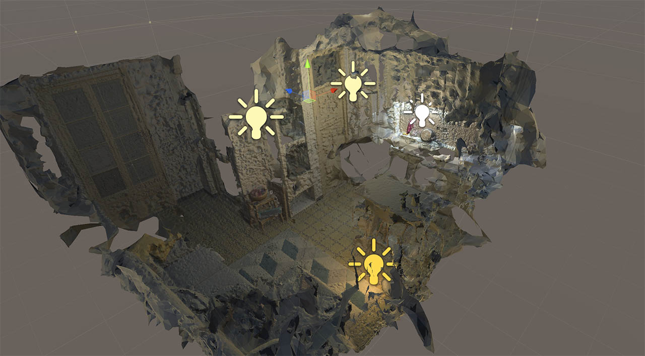
To wrap it up, i decided i would put the model into Unity, and make a VR app for Oculus so that you could walk in the virtual war zone kitchen. For this, I:
- Dropped the new optimized model and the textures into Unity
- Added the model into the scene
- Removed the default directional light, and added point lights where there were light sources on the real scene to simulate the same lighting conditions.
- Downloaded the Oculus package from the asset store
- Placed the Oculus camera prefab in the middle of the reconstructed room
- And built ! Easy
3D Printing
IAAC also has two smaller ABB Robots, so we went on to try to 3d print with the robotic arm and a hand-made extrusion tool made by Eduardo. He designed a vase in Grasshopper, exported the movement data and loaded it into the robot. Then attached the tool, and after a few tweaks it was printing. Much faster than a regular 3d printer. It was especially fascinating to see that once the tip of the extruder was calibrated, you could move the whole robotic arm while that tip stayed perfectly still in the air, much like a mime pretending to hit a wall
>
But now to this week's assignment for 3d printing. We had to design and print an object that could not be made with a substraction method. For this, i wanted to make something really quick to get it out of the way and to test the 3d printing machines and the slicing software with a real example on my own.
After this, time allowing, i wanted to build a Tesseract, which i thought it is not only a really cool object behind an awesome concept, but also a good feasability test for a 3d printed object, since it is so hollow inside.
For the first part, i "designed" a very simple piece, A POLYHEDRON :). Yes, i know what you're thinking. But hey, technically i made it ( didn't download it from internet ) and it is not doable with a substraction technique ( unless you rotate the object and repeat the process several times ).
So i used Blender, and created an icosphere mesh, which very conveniently comes as a default primitive.
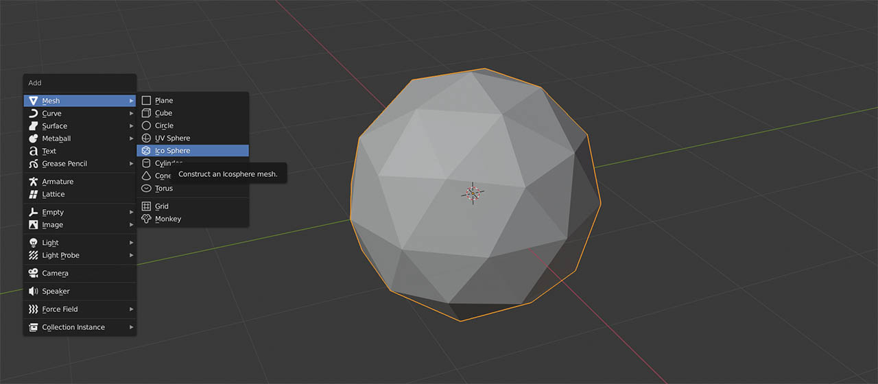
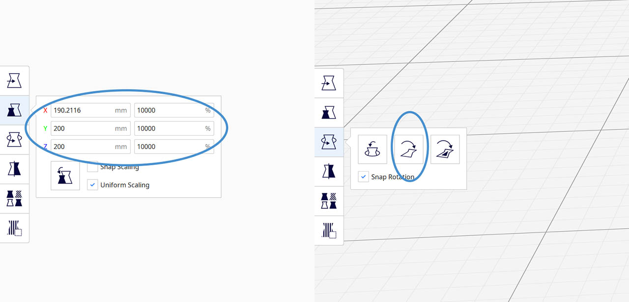
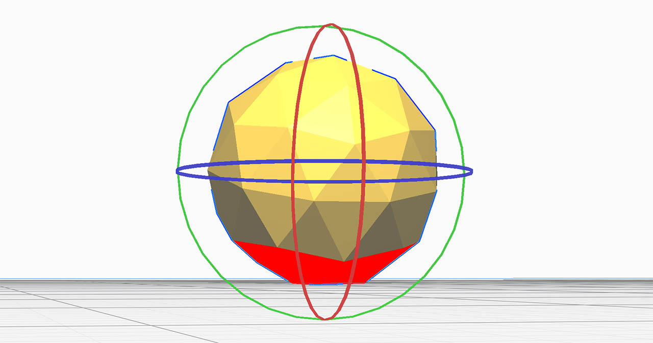
Then exported it as .stl with the default settings, and loaded it into Ultimaker Cura, where i had to both scale the object to the desired size, in my case to ~40mm. of diameter, and rotate it so that one of the faces would sit on the bed and the structure could be build upon it.
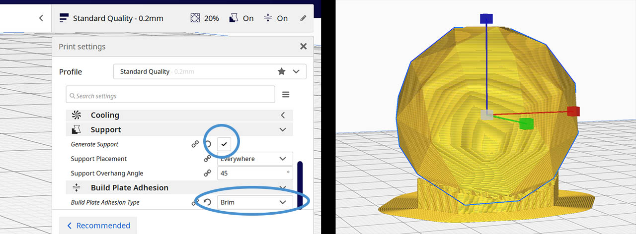
Cura was telling me there were overhang faces that would need support, but i was ok with it, so i let it manage whatever support it needed that i would later remove with a cutter knife.
I also added a brim structure around the base of the object to build upon it to ease the surface adhesion, so that the object wouldn't move.
The next step was to choose the machine i would print with. In my case i used the Creality CR-10. Barcelona's FabLab has very convenient profiles loaded into cura for every 3d printer we have, so you just have to pick yours from the drop down menu and it will load all the settings.
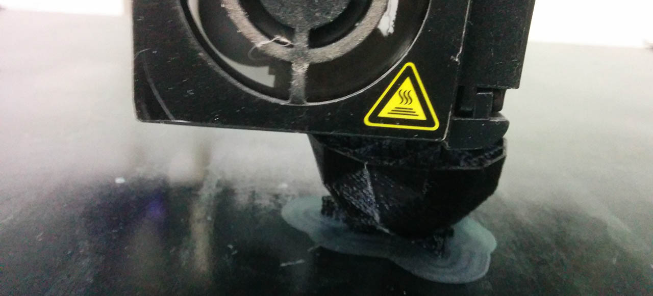
One of the last things to check was what filament i would use to print, so that i could properly calibrate both the bed and the extruder temperature. In my case it was a standard 1.75mm. PLA with a recommended extruder tempreature of 200 +-10 degrees. The recommended bed temperature was 40 degrees. With this info, i started pre-heating both elements, before i went into the final step which was loading the files through a USB dongle into the machine, and starting the process.
[img preheating]
And finally i generated the file from Cura, put it on a USB dongle, plugged it into the Creality and navigated to where the file was via the touch screen, and finally launched the printing process which was estimated to take 1 hour and 10 minutes. Right before starting the process, i had to spray the Creality bed with hair spray, that prevents the model from sticking too much into the glass and makes removal much easier.
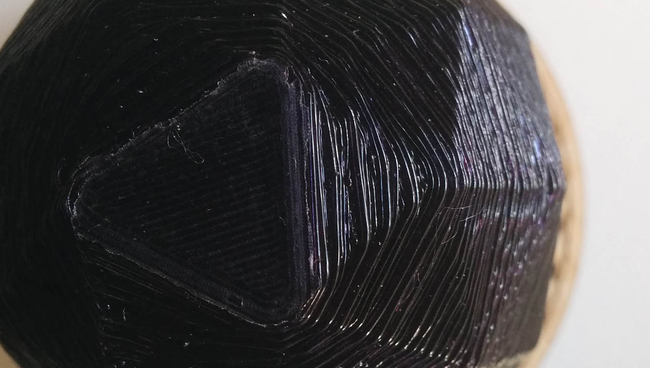
And here you go, a wonderful black plastic polyhedron:
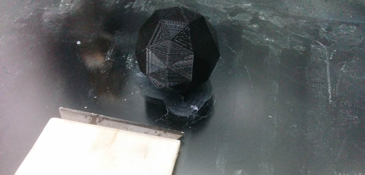
Once it was done, i slowly removed it from the glass bed with a razor-like tool and snapped it free of the brim layer. I did see that the bottom half of the polyhedron is more irregular that the top part. I assume it's because of the inclination, so probably the upper half has the same deformations on the inside, where the support structure is.
I also noticed the structure to support the base overhangs was printed, but susprisingly the polyhedron was not attached to them. I do not know why that happened. You can definitely tell that the first faces growing from the base one are the most deformed ones, most probably because of this
Tesseract ?
Today i learned
- Robots are cool.
- And can be used for many things.
- Photogrammetry is much mature than i thought.
- Skanect needs to update to kinect 2, or azure !
- Try to avoid overhangs on your printed objects.
- Make sure you have the correct 3d printer profile on cura when you export your file. If you load a file with the wrong profile on some 3d printers, it will not only not work, it will also mess up with the configuration of the machine!
The files
- Polyhedron ( Blender, .STL and Gcode )