ASSIGNMENT
Model (draw, render, animate, simulate, …) a possible final project, and post it on your class page with original 2D and 3D files.
2D Design
The final project will have the shape (most likely) of a giant octopus or similar with moveable tentacles and LED stripes on each of them. I will focus on the tentacles at this point, which i envision as a series of links with only limited rotation on the Z axis, like a toy articulated snake, but up and down as opposed to sideways. I might have to do the body in Blender, which seems the best tool to model organic shapes at this point.
First i'll do a very simple draft of what the carcass would look like using a romboid polygonal shape both in raster and vector. I will use Krita, which i did not know before the class for the raster, and illustrator, with which i am a bit familiar for the vector design.
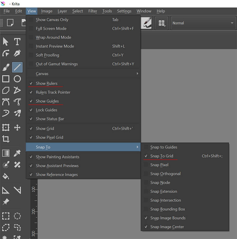
On Krita, i started by go through the View menu and enabling show rulers, show grid, and snap to grid, to help me be accurate:
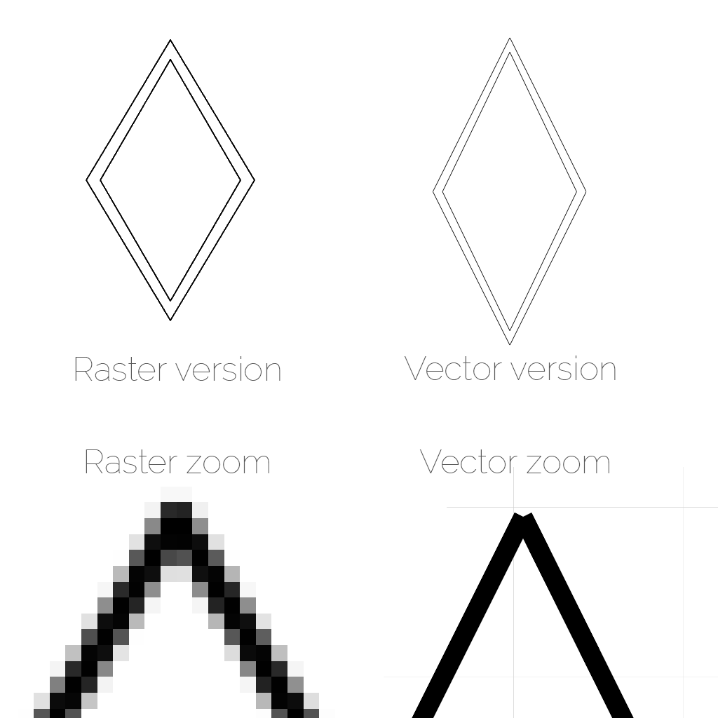
And drew a romboid with double sides using the multiline tool, and then made the vector version of it with Adobe Illustrator using the line tools and snapping on a grid as well. I pasted both in one image, and then zoomed in both in Kira and Illustrator, and captured the screen and pasted the tip of the romboid underneath, in this 4-way comparison.
As we can see and we've seen in the lecture, when zooming in, the raster version is limited by the resolution, so we can see the pixels, while the vector version doesn't loose any:
3D Design
After having seen FreeCAD, Rhino + Grasshopper, Fusion 360 and Blender, i think the easiest way for me at this point to model a draft of the final project is Fusion 360.
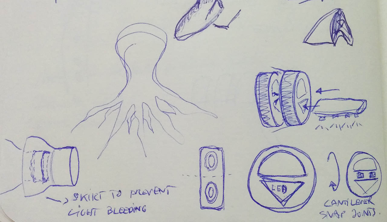
I started by sketching what a link would look like, and how they would connect with each other on paper:
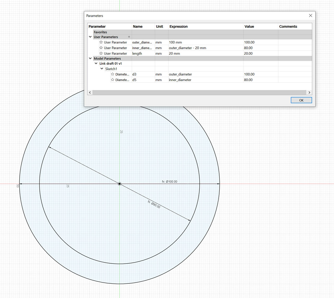
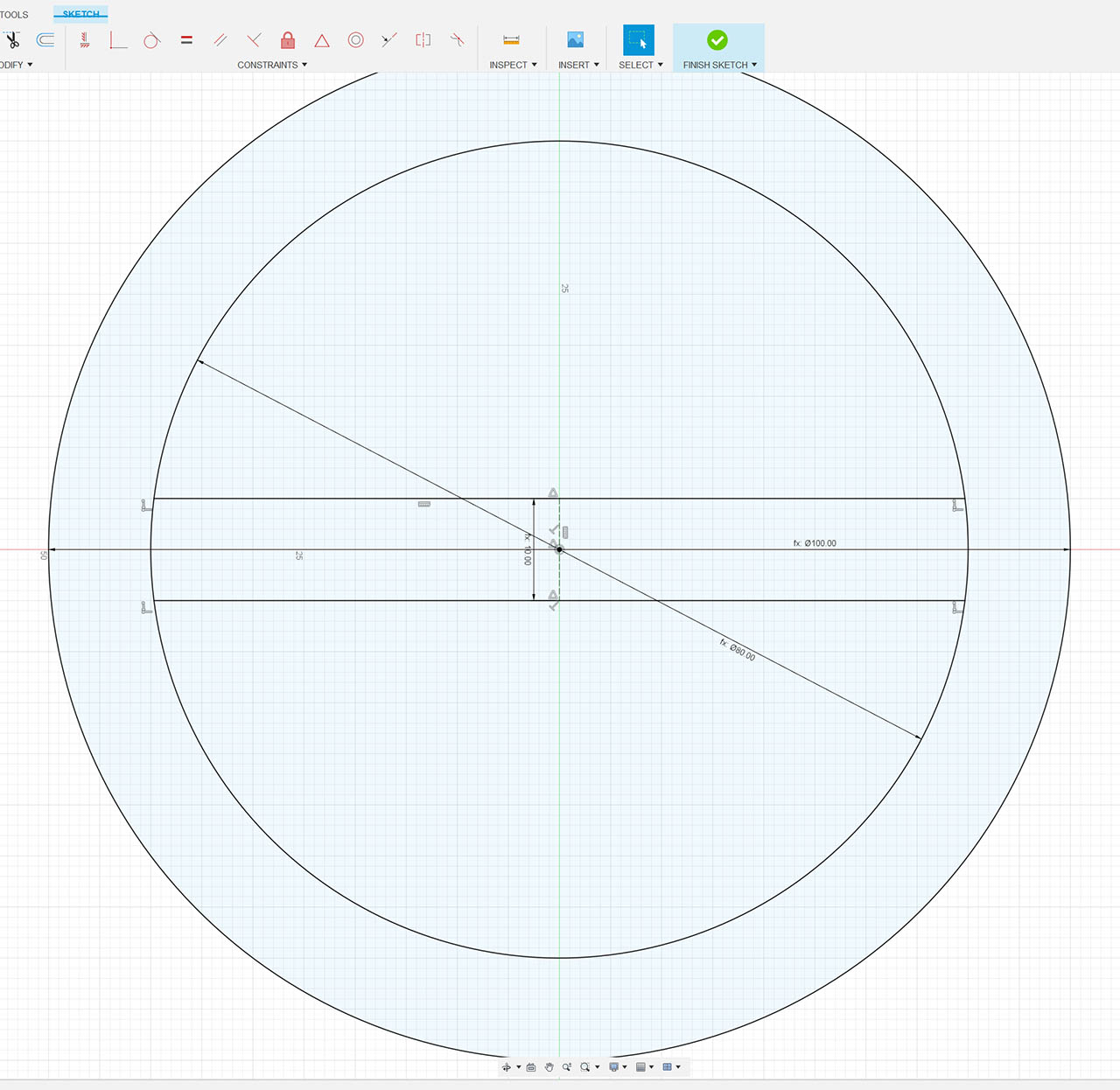
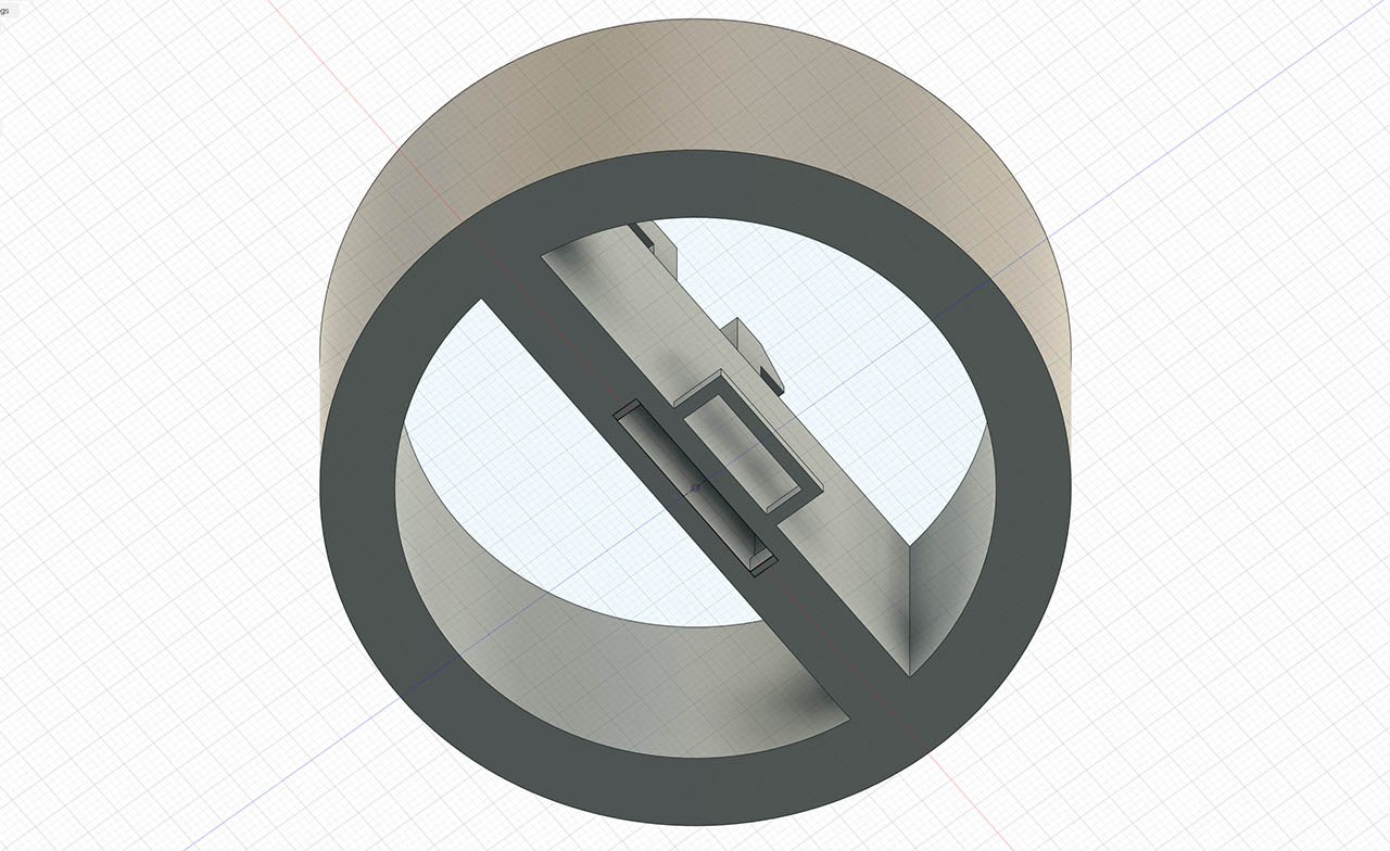
Then i started modeling a link, taking into account parametric design. In this capture for instance you can see how parameters are set for outer diameter, and inner diameter as a function of the outer one.
I then designed the central section where the snapping mechanism to chain links together will be. To do so, i first added a construction line that will determine the width of the central section via a parameter, so it is configurable. I did so by creating a line, assigning it length = the parameter, and setting the constraint of midpoint to the center of the piece.
I then drew the top and bottom lines, linking them to the inner circle, and setting a midpoint constraint with both ends of the central line.
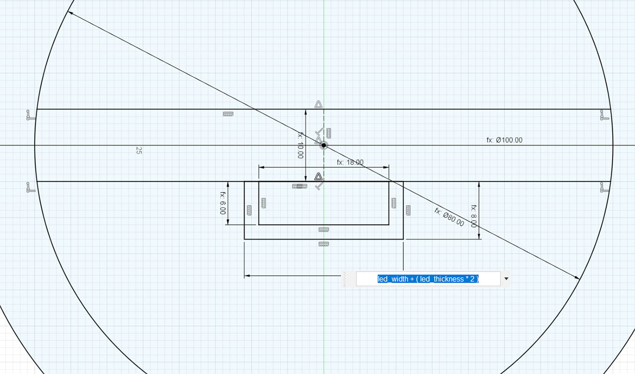
Next is the wedge that will hold the LED strip. First i defined the width and height of the led strip as parameters, and then i drew a rectangle with that size attached to the bottom line and centered, using again the midpoint constraint with the end of the construction line that determines the width of the central piece. I then made another rectangle with width and height equal to the previous one plus another parameter, that will determine the led strip holder thickness. Since the rectangle base is attached to the bottom line, the formula for the width of this rectangle will be led_width + (led_thickness*2)
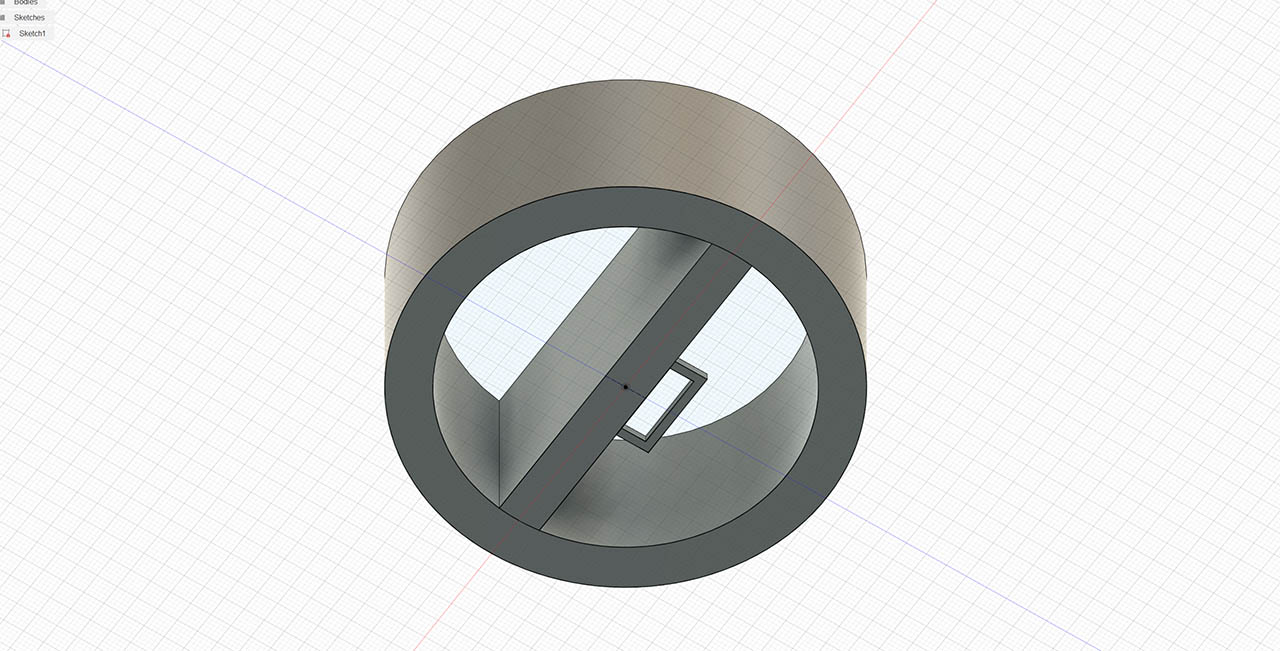
I finally extruded the sketch to see how it's looking like. I still need to add the locking mechanism between links.
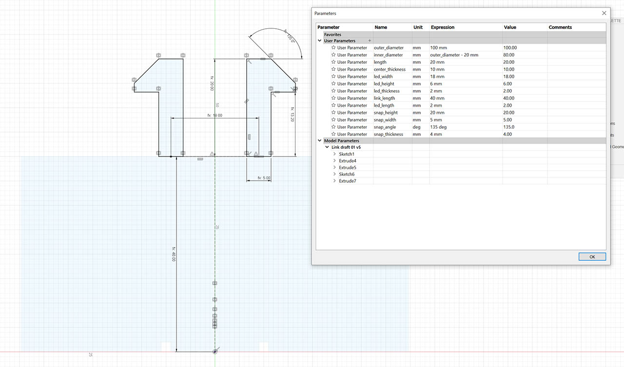
For the snap mechanism i created a new sketch on the XY axis and drew a P-shaped or cantilever piece. I added parameters for its height, width and angle, and then used construction lines to align it with the rest of the piece. I finally mirrored one piece to get the other one. I will probably need to change this part as i have never built anything like this and have no experience whatsoever. But this is the idea i'm after right now. The goal is that each of this links will connect with the next one, creating a chain that will make the full articulated tentacle of the creature.
After extruding this last part, i had to move the two new bodies to align them at the center of the piece. I did this manually, but later on i learned that you can create an offset plane and use it to align things to it.
The last part was carving the hole where the snap pieces will go. I measured the size of the hole with all the parameters, using the formula led_width + ( led_thickness * 2 ) + ( snap_width / 2 ) + snap_width - snap_difference (!!!!) and then added the two extra spaces at the top that will create the T shaped hole where the snap pins will go. In this final render, you can see all the parts
Other programs
I wanted to try grasshopper after learning about it on the local class. i thought it was very versatile. But sadly i didn't have enough time during the week. I will check it out in the next weeks though.
I did create an interactive animation with Unity, since i am proficient with it, as i use it at my day to day work. I wanted to not only create a visualization of a possible shape of the final project, but program in a bit of the behaviors that i have in mind with it, to get a sense of how it would be like in reality. My goal is both to program a midi-input interaction via a keyboard with knobs and faders, as well as program an automated mode where the piece will cycle through different visualization modes. If there's enough time, i would like to add different input sensors, like e heart-rate sensor or a glove with accelerometers to control the movement of the legs.
I started by finding a central shape for the body, since i still don't have a clear idea of what it will be and i wanted to focus on the moving legs, which is, i think, the hardest part. I was looking for an octopus initially, but then i found this jellyfish that i really liked. So i dropped it into Unity for now, until i model the light sculpture myself.
The model was made by: mellydeeis Model: Jellyfish
I then programmatically rendered all the moving links of the legs, exposing several parameters to easily change how many legs, or how many links per leg we want:
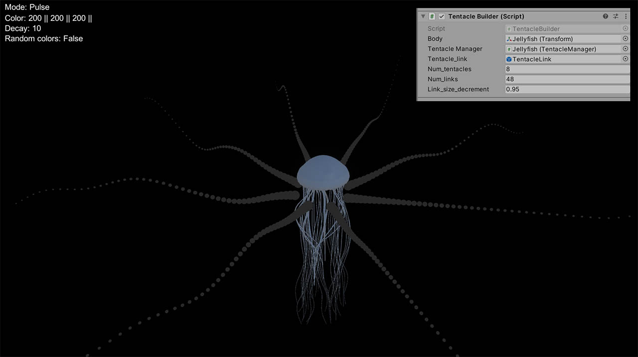
Next, i programmed the organic movement of each link chain using perlin noise, where each link samples the function at a different point on the same dimension, using the time variable:
        for (int i = 0; i < tentacles.Count; i++)

        {

            for (int j = 0; j < tentacles[i].tentacle.Count; j++)

            {

                float mov = (j/20f)*Mathf.PerlinNoise((Time.time+(j/10f))*.5f, i*10f) - .5f;

                temp = tentacles[i].tentacle[j].transform.position;

                temp.y = tentacle_base.transform.position.y + mov;

                tentacles[i].tentacle[j].transform.position = temp;

            }

        }
and finally added in some key bindings to trigger different visualization modes. The last step was to add post-processing effects like bloom, to simulate the shininess of LED strips. The material i used is a simple unlit material with an HDR color. Here's a video with some of them following with keystrokes the song Electronic Performers by Air:
Assignment 3 - Unity video from magicobicho on Vimeo.
Assignment files
- The raster file is embedded at the beginning of the assignment, since it's just the image.
- Here's the vector file with illustrator: Romboid
- Here's the file exported from Fusion: Tentacle Link (fusion) and in DXF format: Tentacle Link (DXF)
- Here's a link to the Unity project, on github, since it was too big to host in here: Unity project