15. Networking and Communcation
The objective of this week is to first, work with a group Send a message between two projects, second to design, build, and connect wired or wireless node(s) with network or bus addresses.
Group Assignment
You can find our group assignment in this Link
Networking and Communcation
Serial Bus
In telecommunication and data transmission, serial communication is the process of sending data one bit at a time, sequentially, over a communication channel or computer bus. Many communication systems were generally designed to connect two integrated circuits on the same printed circuit board, connected by signal traces on that board (rather than external cables).
Serial communication on pins TX/RX uses TTL logic levels (5V or 3.3V depending on the board). They are used for communication between the PCB and a computer or other devices.
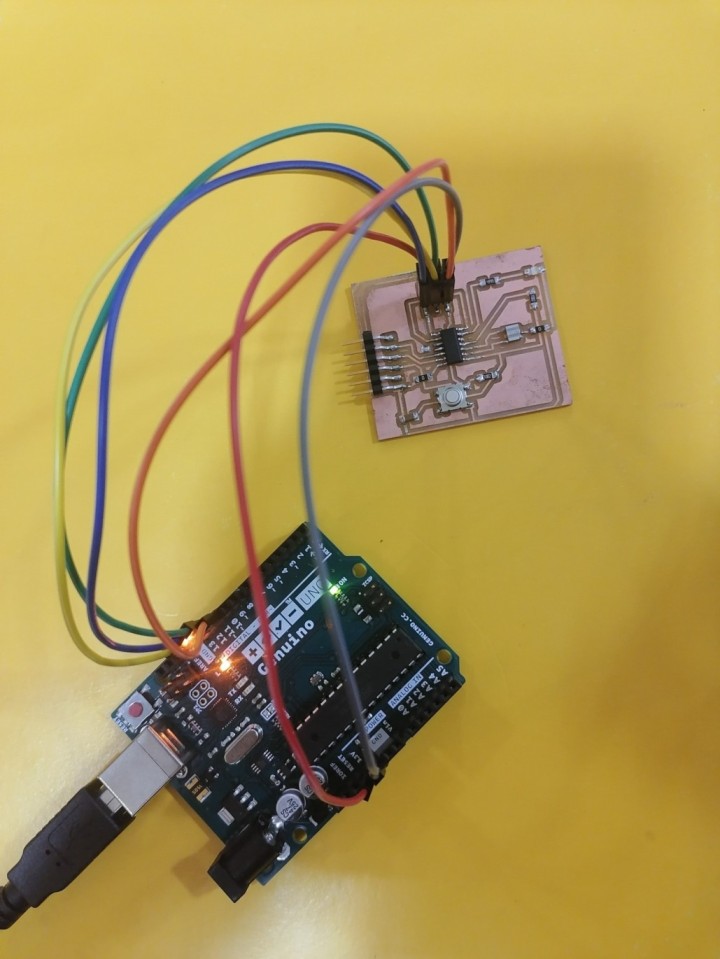
Serial Bus (Arduino and ATtiny44)
In this part of the assignment I used the PCB that I made in week7 with ATtiny44, the PCB in week10 with ATMega325P and Arduino UNO. I communicate with them through serial bus.
I follow the following stepes:
-
Open Arduino IDE and go to file >> examples >> Arduino ISP and upload the example to the Arduino uno board to set it as programmer.
-
Connect the ATtiny 44 board to Arduino UNO through AVR ISP 6-pins as in week7.
- Select the right settings in the tools bar.
-Select the board From the toolbar go to Tools << Board << ATtiny 24/44/84 << ATtiny44.
-Select the processor From the toolbar go to Tools << processor << ATtiny44.
-Program the Arduino From the toolbar go to Tools << clock << External 20 MHz.

- Upload the following code the following code by selecting scketch >> upload using progarmmer but keep in mind to change the Tx, Rx and LED pins and also the node number to the right ones.
#include <SoftwareSerial.h>
SoftwareSerial mySerial(PA1,PA0); //RX, TX
int v=0;
int nodeid=3;

void setup() {
  mySerial.begin(9600);
  pinMode(PA7, OUTPUT); // white led
}

void loop() {
  while (mySerial.available () == 0 ) {}
  v = mySerial.parseInt();
  mySerial.println(v);
  if(v == nodeid)
{
  digitalWrite(PA7,HIGH);
  delay(500);
  digitalWrite(PA7,LOW);
  delay(500);
  digitalWrite(PA7,HIGH);
  delay(500);
  digitalWrite(PA7,LOW);
}
else
{
  digitalWrite(PA7,LOW);
 }
}
Serial Bus (Arduino and ATmega325P)
I follow the following stepes:
-
Connect the ATmega325P board to Arduino UNO through AVR ISP 6-pins as in in week10.
-
Select Arduino UNO in tool bar is this is the same microcntoller that we use in Arduino.

- Upload the following code the following code by selecting scketch >> upload using progarmmer but keep in mind to change the Tx, Rx and LED pins and also the node number to the right ones.
int v=0;
int nodeid=1;

void setup() {
  Serial.begin(9600);
  pinMode(13, OUTPUT); // white led
}

void loop() {
  while (Serial.available () == 0 ) {}
  v = Serial.parseInt();
  Serial.println(v);
  if(v == nodeid)
{
  digitalWrite(13,HIGH);
  delay(500);
  digitalWrite(13,LOW);
  delay(500);
  digitalWrite(13,HIGH);
  delay(500);
  digitalWrite(13,LOW);
}
else
{
  digitalWrite(13,LOW);
 }
}
Arduino Programming
Upload the following code to the Arduino but keep in mind to change the Tx, Rx and LED pins and also the node number to the right ones.
int v=0;
int nodeid=2;

void setup() {
  Serial.begin(9600);
  pinMode(13, OUTPUT); // white led
}

void loop() {
  while (Serial.available () == 0 ) {}
  v = Serial.parseInt();
  Serial.println(v);
  if(v == nodeid)
{
  digitalWrite(13,HIGH);
  delay(500);
  digitalWrite(13,LOW);
  delay(500);
  digitalWrite(13,HIGH);
  delay(500);
  digitalWrite(13,LOW);
}
else
{
  digitalWrite(13,LOW);
 }
}
From the serial monter type the node number and notice which LED will turn on.
Connections:
- connect all the Rx pins of the 3 circuts in one node in the bread board.
- connect all the Tx pins of the 3 circuts in one node in the bread board.
- Connect the 3 circuit with VCC and GND

The final result is shown in the video below