10. Input devices
The objective of this week is to first, with a group Probe an input device(s)’s analog and digital signals, second to Individually, to Measure something by adding a sensor to a microcontroller board that you have designed and read it.
Group Assignment
You can find our group assignment in this Link
PCB Design
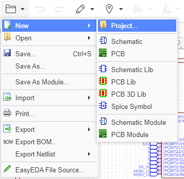
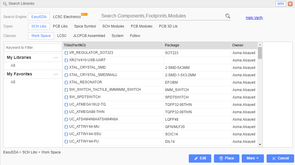
In this week I designed a circuit that I will use in my final project. Since I will use many inputs and outputs, I chose to go with Atmega328p as it has many input and output pins. I started the design by trying a new software which is EsayEDA, I found it much easier than Eagle. So, to start the design I follow the following steps:
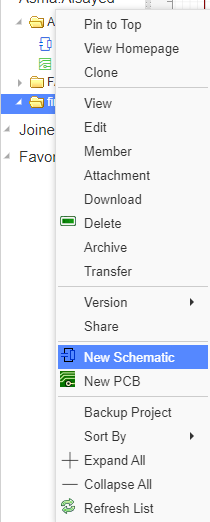
- Open EasyEDA >> File >> new project, select a name for the project then highlight the project << Right click<< new schematic.
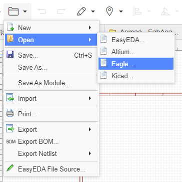
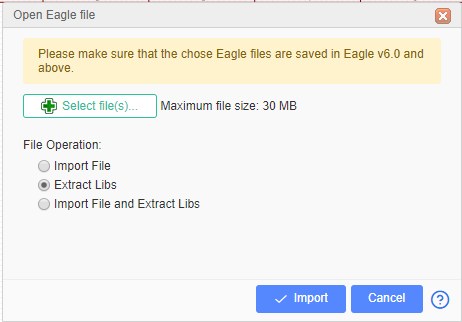
- Go to file >> import >> Eagle >> select files to browse to the fab library and select extract Libs >> Import >> Check all the boxes next to the symbol and click the “Add to My Library” button.
-
Click OK after successful import.
-
Insert all the component by clicking on the library icon and search for them.

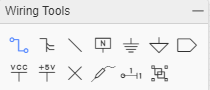
- Connect the component together by using the wire from the wiring tools.
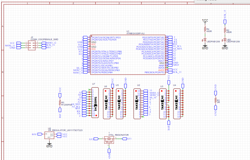
The final result of the schematic design.
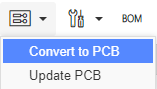
- Go to convert icon << convert to PCB.
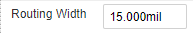
- Arrange the wires so their will be no intersection between them but make sure that the width routing is 15 mil.
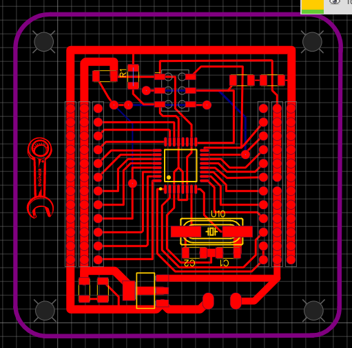
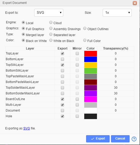
- Go to file >> export >> SVG >> select the red layer >> and export.
-
Repeat step 8 to export the outline and the holes.
-
Open the file in Mods and select the proper setting as in week7 to generate the rml file.
-
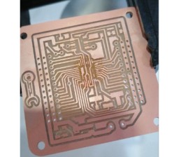
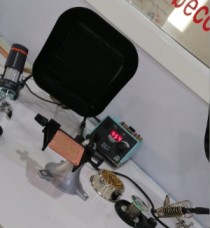
Open the rml file with SRM-20 milling machine software, adjust your origin and the mailing bit.
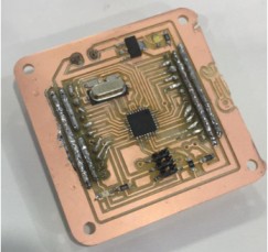
- Solder the circuit components
The final result
-
Test The circuit by connecting the PCB ISP with the Arduino pins by the following configuration:
-
Arduino GND connects to Pin 6 (GND)
-
Arduino Pin 13 connects to Pin 3 (SCK)
-
Arduino Pin 12 connects to Pin 1 (MISO)
-
Arduino Pin 11 connects to Pin 4 (MOSI)
-
Arduino Pin 10 connects to Pin 5 (Slave Reset)

- Upload a small blinking code by using the arduino as a programmer to make sure that the circuit is working properly
void setup() {
  pinMode(LED_BUILTIN, OUTPUT);
}

void loop() {
  digitalWrite(LED_BUILTIN, HIGH);
  delay(1000);
  digitalWrite(LED_BUILTIN, LOW);
  delay(1000);
}
Flame sensor
Flame sensors is a digital sensor used for short range fire detection and can be used to monitor projects or as a safety precaution to cut devices off / on.

Specifications
Operating Voltage: 3.3V to 5V DC Operating Current: 15 mA Output Digital: 0V to 5V LEDs indicating output and power
Pin details
VCC = 3.3V to 5V DC GND = Ground DO = Digital Output
Conection
The configuration pin of HC-SR04 is VCC, TRIG , ECHO, and GND. The supply voltage of VCC is +5V and you can attach TRIG and ECHO pin to any Digital I/O in your Arduino Board.
The materials that we need to make this project:
-
PCB
-
Arduino UNO.
-
Flame sensor .
-
Male to Female Jumper Wires.
-
Flame source (Lighter).
I Connect the VCC and GND pins to the 5V and GND in the bread boared , then I connect digitl output pin of the sensor to pin 9, a red LED with 220 ohms to pin 8 and a red LED with 220 ohms to pin 2.
Programing
First, I defined the pins connection, then I defined a specific variable “fd” to save the reading of the flame sensor in it. In void setup I defended the pin mode which pin is used as input and which pin is used as an output. In void loop I started an if statement so whenever the reading value of the sensor is equal to zero which means that there is a flame source the red LED will turn on and the green LED will turn off because the sensor is digital. Once there is no flame source the Green LED will be on and the red one turns off.
int redLED=8;
int greenLED=2;
int flame= 9;
int fd;

void setup() {
  // put your setup code here, to run once:
  pinMode(redLED, OUTPUT);
  pinMode(greenLED, OUTPUT);
  pinMode(flame, INPUT);
}

void loop() {
  fd= digitalRead(flame);
  // put your main code here, to run repeatedly:
  if (fd == 0)
  {
    digitalWrite(redLED, HIGH);
    digitalWrite(greenLED, LOW);
  }
  else
  {
    digitalWrite(redLED, LOW);
    digitalWrite(greenLED, HIGH);
    }

    delay(100);
}
The results of both the connection and the programming is shown in the video
Ultrasonic sensor
Ultrasonic Sensor HC-SR04 is an analog sensor that can measure distance. It emits an ultrasound at 40 000 Hz (40kHz) which travels through the air and if there is an object or obstacle on its path It will bounce back to the module. Considering the travel time and the speed of the sound you can calculate the distance.

Conection
The configuration pin of HC-SR04 is VCC, TRIG , ECHO, and GND. The supply voltage of VCC is +5V and you can attach TRIG and ECHO pin to any Digital I/O in your PCB.
The materials that we need to make this project:
-
PCB
-
Arduino UNO.
-
Ultrasonic Sensor HC-SR04.
-
Male to Female Jumper Wires.
-
Bread board
I Connect the VCC and GND pins to the 5V and GND in the bread boared , then I connect TRIG to pin 9 and ECHO to pin 2 in the digital pins and a red LED with 220 ohms.
Programing
First, I defined the pins connection, then in the void setup() I initialized the pins of the sensor and the led as input or output , then I set the LED to be turned off at the beginning.
In the void loop(), then I establish variables for duration of the sensor wave, and the distance result in inches and centimeters.
The sensor wave is triggered by a HIGH pulse of 2 or more microseconds then I give a short low pulse to ensure a clean high pulse. Then I save the reading on echo pin in a variable which I called duration. To convert the time into distance two I used two functions.
-
“microsecondsToInches(duration)”: According to datasheet for the sensor wave, there are 73.746 microseconds per inch. This gives the distance travelled by the senor wave, outbound and return, so we divide by 2 to get the distance of the obstacle.
-
“microsecondsToCentimeters(duration)”: The speed of sound is 340 m/s or 29 microseconds per centimeter. The wave of the sensor travels out and back, so to find the distance of the object we take half of the distance travelled.
The result of the two function is saved in two variables “inches” and “cm”.
The if statement is used to compare the measured distance with the maximum allowed distance which is 5 inches , if the measured distance is less than 5 inches the red led will turn on to indicate that we are too close to the sensor, else the red led will turn off.
#define trigPin  2
#define echoPin 9
#define ledRed 8

void setup() {

  pinMode(trigPin, OUTPUT);
  pinMode(echoPin, INPUT);

  pinMode(ledRed, OUTPUT);
  digitalWrite(ledRed, LOW);

}

void loop()
{

  long duration, inches, cm;

digitalWrite(trigPin, LOW);
delayMicroseconds(2);
digitalWrite(trigPin, HIGH);
delayMicroseconds(5);
digitalWrite(trigPin, LOW);

 duration = pulseIn(echoPin, HIGH);

inches = microsecondsToInches(duration);
 cm = microsecondsToCentimeters(duration);


  if(inches < 5) {
    digitalWrite(ledRed, HIGH);
    delay(100);
  } else {
     digitalWrite(ledRed, LOW);
     delay(100);
  }

  delay(200);
}

long microsecondsToInches(long microseconds)
{
  return microseconds / 74 / 2;
}

long microsecondsToCentimeters(long microseconds)
{

  return microseconds / 29 / 2;
}
The results of both the connection and the programming is shown in the video
I tried another code to see the input singal
#define echoPin 2 // attach pin D2 Arduino to pin Echo of HC-SR04
#define trigPin 3 //attach pin D3 Arduino to pin Trig of HC-SR04

// defines variables
long duration; // variable for the duration of sound wave travel
int distance; // variable for the distance measurement

void setup() {
  pinMode(trigPin, OUTPUT); // Sets the trigPin as an OUTPUT
  pinMode(echoPin, INPUT); // Sets the echoPin as an INPUT
  Serial.begin(9600); // // Serial Communication is starting with 9600 of baudrate speed
  Serial.println("Ultrasonic Sensor HC-SR04 Test"); // print some text in Serial Monitor
  Serial.println("with Arduino UNO R3");
}
void loop() {
  // Clears the trigPin condition
  digitalWrite(trigPin, LOW);
  delayMicroseconds(2);
  // Sets the trigPin HIGH (ACTIVE) for 10 microseconds
  digitalWrite(trigPin, HIGH);
  delayMicroseconds(10);
  digitalWrite(trigPin, LOW);
  // Reads the echoPin, returns the sound wave travel time in microseconds
  duration = pulseIn(echoPin, HIGH);
  // Calculating the distance
  distance = duration * 0.034 / 2; // Speed of sound wave divided by 2 (go and back)
  // Displays the distance on the Serial Monitor
  Serial.print("Distance: ");
  Serial.print(distance);
  Serial.println(" cm");
}
