9. Embedded programming
The objective of this week is to first, work with a group Compare the performance and development workflows for different microcontroller families, second to Read the datasheet for the microcontroller you are programming. Finally, to Program the board you have made to do something, with as many different programming languages and programming environments as possible.
Group Assignment
You can find our group assignment in this link
Data Datasheet
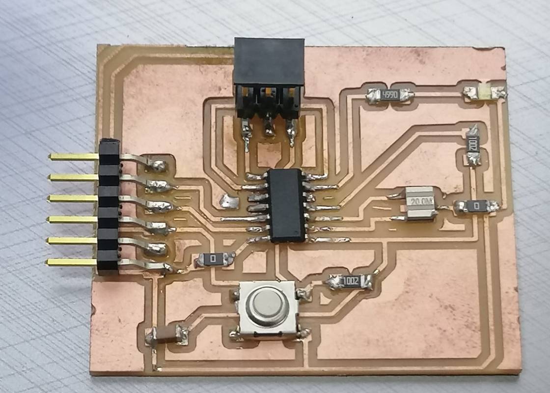
In this week I use the PCD that I created link, which is ATtiny44
To program any microcontroller or to connect it is important to read the Datasheet, there are two types of data sheet summary which gives you the important information and complete datasheet which gives you detailed information about your microcontroller. I decide to have an overview on the summary datasheet as I long as I did not need the complete one.
One of the most important things that I need to know is the circuit diagram of ATtiny44 and the pin description to know the name of each pin to understand the function of it in the circuit.
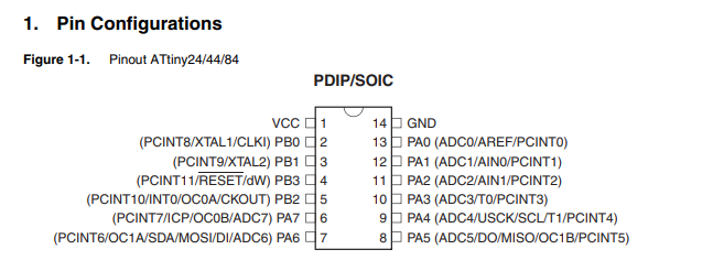
| Pin | Description |
|---|---|
| VCC | Supply voltage |
| GND | Ground |
| Port B (PB3:PB0) | Port B is a 4-bit bi-directional I/O port with internal pull-up resistors selected for each bit. The Port B output buffers have symmetrical drive characteristics with both high sink and source capability except PB3 which has the RESET capability. |
| Port A (PA7:PA0) | Port A is a 8-bit bi-directional I/O port with internal pull-up resistors (selected for each bit). The Port A output buffers have symmetrical drive characteristics with both high sink and sourcecapability. |
| RESET | Reset input. A low level on this pin for longer than the minimum pulse length will generate a reset, even if the clock is not running and provided the reset pin has not been disabled. |
To avoid burning my ATtiny44 and to make it work efficiently I need to know the voltage range and speed.
| Speed (MHz) | Power Supply |
|---|---|
| 10 | 1.8 - 5.5V |
| 2 | 2.7 - 5.5V |
Program the board
Arduino IDE
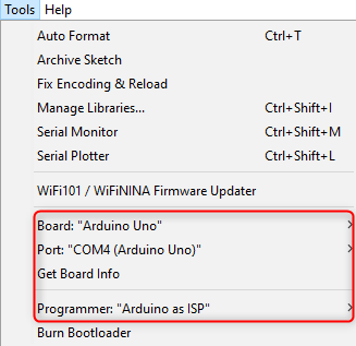
After I was done with reading the datasheet, I decide to try to program it with C++ language at Arduino IDE. The type of Arduino that I use as programmer is Arduino UNO. The steps for how to set Arduino as programmer is explained below
-
Connect the Arduino board to your PC
-
Select the board
From the toolbar go to Tools << Board << Arduino UNO. -
Select the port
From the toolbar go to Tools << port<< select the correct port for me it was COM4. -
Select your programmer
From the toolbar go to Tools << programmer << Arduino as ISP. -
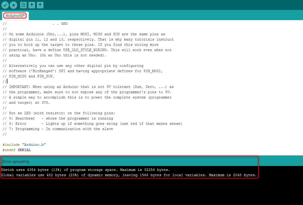
Program the Arduino
Go to file <<example << ArduinoISP << ArduinoISP.
upload the ready example to Arduino.
The next step is to connect My ATtiny board with the Arduino board, to do this I need to connect the ATtiny44 ISP header to Arduino pins. The ISP header pin configuration is shown below
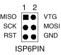
The connection must be as follow * Arduino 5V connects to Pin 2 (Vcc)
-
Arduino GND connects to Pin 6 (GND)
-
Arduino Pin 13 connects to Pin 3 (SCK)
-
Arduino Pin 12 connects to Pin 1 (MISO)
-
Arduino Pin 11 connects to Pin 4 (MOSI)
-
Arduino Pin 10 connects to Pin 5 (Slave Reset)
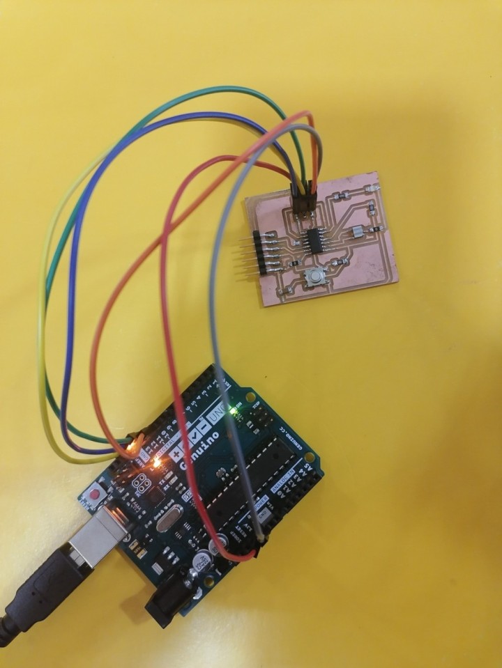
The result of the conection
After I was done with the connection I change the setting of the Arduino IDE to program the ATtiny44 PCB instead of the Arduino microcontroller to do this go to file << preferences << additional boards manger URL and paste this link “https://raw.githubusercontent.com/damellis/attiny/ide-1.6.x-boards-manager/package_damellis_attiny_index.json” , then again go to tools and change the setups to the following
-
Select the board
From the toolbar go to Tools << Board << Board manger << in the search bar type ATtiny and install the library after the installation is done again go to Tools << Board << ATtiny 24/44/84. -
Select the processor
From the toolbar go to Tools << processor << ATtiny44. -
Program the Arduino
From the toolbar go to Tools << clock << select the correct clock rather it is external or internal with the correct value for me it was External 20 MHz . -
Select the port
From the toolbar go to Tools << port<< select the correct port for me it was COM4. -
Select your programmer
From the toolbar go to Tools << programmer << Arduino as ISP.
Moving to programming part, I open Arduino IDE the following window will open
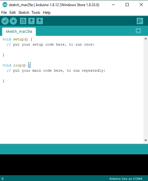
The code in the pictuer is as follow
void setup() {
  // put your setup code here, to run once:

}

void loop() {
  // put your main code here, to run repeatedly:

}
In void setup there is a comment written by default that says > “put your setup code here, to run once” that means that you should identify which pin is used as input and which pin used as an output. In my ATtiny 44 PCB the LED is connected to pin PA7 while the button is connected to PA3 so I identify PA3 as an input and PA7 as output.
void setup() {
  // put your setup code here, to run once:
pinMode(PA3, INPUT);
pinMode (PA7, OUTPUT);
}
In void loop also you can find a comment that says “put your main code here, to run repeatedly” which means that this the space which you can write the rest of the code here after you are done with identifying the variables and I/o pins. For example you can start write the loop statements such as if statement , while, for , etc.
In my ATtiny44 I want the LED turns on if I push the button and turns off if I release it so I try to translate what I want to C++ by first introduce a variable before both the void setup and void loop to save the digital value of the button in it I name it –BS—and make it as integer value and equal to zero.
int BS = 0;
Then in the void loop I represent the same variable and make it equal to the digital read of the button pin which is PA3, what I mean by digital is zeros and ones. Zero goes for low or open circuit which the voltage reading is zero and one goes for high or close circuit which the voltage reading is 5.
After that I start to write the if statement, I begin with the case which the button is pushed which mean the current is passing through and there is a voltage that mean the microcontroller digital reading is high that was my input. The result or the desired output is turn the LED on so I am telling the microcontroller if the previous statement happen write high which means sent current to the LED pin. Then I use else which means other than the previous condition stop writing or sending current to the LED so it will remain off.
if (BS == HIGH){
digitalWrite(PA7, High);
 }

else
{
digitalWrite(PA7, Low);
}

After that we need to upload the code to the ATtiny44 PCD that is could be done by clicking on sketch << Upload using programmer
The final result is showing in the video below.
Another programming
I read that the LED is able to converte light into either current or voltage so we can use it as a photodiode light sensor / detector, In addition to emitting light. This capability may be used in a variety of applications including ambient light level sensor and bidirectional communications. As a photodiode, an LED is sensitive to wavelengths equal to or shorter than the predominant wavelength it emits.
so I tried another code which will test the output signal of the LED if it will be the same signal if we change the light enviroment around it.
An Analog to Digital Converter (ADC) is a very useful feature that converts an analog signal on a pin to a digital number. By converting from the analog world to the digital world, we can begin to use electronics to interface to the analog world around us. In the LED we convert the light which the analog signal into digital number that the microcontroller can read and understand.
//this code is meant to use an led as a light sensor as the analog value tends to change with light
#include <SoftwareSerial.h>
#define RX PA1
#define TX PA0
SoftwareSerial mySerial(RX, TX);
int sensePin = PA7; //attiny led pin
int sensorInput; //The variable we will use to store the sensor input
void setup() {

mySerial.begin(9600);
pinMode (sensePin, INPUT);
}
void loop() {
// put your main code here, to run repeatedly:
sensorInput = analogRead(sensePin); //read the analog sensor and store it
mySerial.println(sensorInput);
}
The result is shown below:
As we can see from the result that as I am hiding the LED with my finger the signal change.
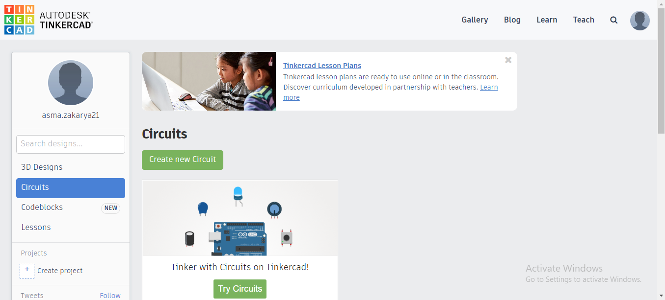
programming by blocks
I use thinkercad to program the circuit that I made in week10:
- Sign in thinkercad by using Gmail.
- Creat a new circuit project.
- Insert the Arduino board in the gray space and click on code.
- Inset the block that will help you to write your program.
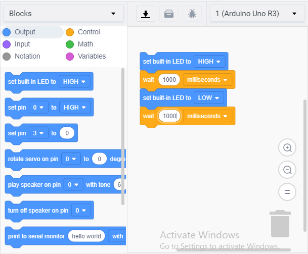
- Download the code by clicking on the download icon and open it with Arduino IDE software.
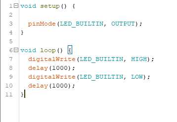
- Upload the code to my circuit by using the Arduino board as a programmer.
I found out that programming with blocks is much easier than Arduino IDE as I did not have to write the whole code however Arduino IDE is more accurate.