12. Output devices
The objective of this week is to first, with a group Measure the power consumption of an output device, second to Individually, to Add an output device to a microcontroller board you’ve designed and program it to do something.
Group Assignment
You can find our group assignment in this Link
Output devices
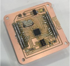
To fulfill this week objectives, I use the same circuit that I made in week 10.
Servo Motor
A servo motor has everything built in: a motor, a feedback circuit, and most important, a motor driver. It just needs one power line, one ground, and one control pin. Here is the link for more information about the servo

Connection
The materials that we need:
-
Arduino UNO
-
Servo motor
-
Male to Male Jumper Wires
-
PCB
To connect the motor with the PCB 1. The servo motor has a female connector with three pins. The darkest or even black one is usually the ground. Connect this to the GND.
-
Connect the power cable to 5V on the PCB.
-
Connect the remaining line on the servo connector to a digital pin on the PCB for me it was pin 2.

Programing
I start the programming by following the stepes below:
- Including the servo library.
- Declare the Servo pin.
- Create a servo object.
- In void setup, We need to attach the servo to the used pin number.
- In void loop, Make servo go to 0 degrees then to 180 degrees.
#include <Servo.h>

int servoPin = 2;

Servo Servo1;
void setup() {

   Servo1.attach(servoPin);
}
void loop(){

   Servo1.write(0);
   delay(4000);

   Servo1.write(180);
   delay(4000);
}
The final result is shown in the video below
PIEZO SPEAKER
PIEZO SPEAKER (PKM22EPP-40) is a small yet efficient component to add sound features to our project/system. It is very small and compact 2-pin structure hence can be easily used on breadboard, Perf Board and even on PCBs which makes this a widely used component in most electronic applications.

Applications of Buzzer
Alarming Circuits, where the user has to be alarmed about something Communication equipments Automobile electronics Portable equipments, due to its compact size
Features and Specifications
- Rated Voltage: 6V DC
- Operating Voltage: 4-8V DC
- Rated current: < 30mA
- Sound Type: Continuous Beep
- Resonant Frequency: ~2300 Hz
- Small and neat sealed package
- Breadboard and Perf board friendly
Connection
The materials that we need:
-
Arduino UNO
-
Buzzer
-
Male to Male and Male to female Jumper Wires
-
PCB
To connect the Buzzer with the PCB 1. The Buzzer has a Male connector with two pins: pin (1) is Identified by (+) symbol or longer terminal lead. Can be powered by 6V DC, and pin(2) which is Identified by short terminal lead. Typically connected to the ground of the circuit.

-
Connect the power the negative pin to the GND.
-
Connect the positive pin to pin 9.

Programing
I start the programming the Buzzer by first apply a sample code which I used in it a new function which is tone() which is used to generates a square wave of the specified frequency on a pin. If we use the tone function a duration can be specified, otherwise the wave continues until a call to noTone(). The pin can be connected to a piezo buzzer or other speaker to play tones.
The function parameters are as follows: - pin: the Arduino pin on which to generate the tone. - frequency: the frequency of the tone in hertz. Allowed data types: unsigned int. - duration: the duration of the tone in milliseconds.
tone(pin, frequency)
tone(pin, frequency, duration)
I upload a simple code to test how the Buzzer will work with the spesified function
const int buzzer = 9; //buzzer to arduino pin 9

void setup(){

  pinMode(buzzer, OUTPUT); // Set buzzer - pin 9 as an output

}

void loop(){

  tone(buzzer, 1000); // Send 1KHz sound signal...
  delay(1000);        // ...for 1 sec
  noTone(buzzer);     // Stop sound...
  delay(1000);        // ...for 1sec

}
Then I found by searching a frequancy note for a birthday song so I program my buzzer according to it

const int buzzer = 9; //buzzer to arduino pin 9


void setup(){

  pinMode(buzzer, OUTPUT); // Set buzzer - pin 9 as an output

}

void loop(){

  tone(buzzer, 262); // Send 1KHz sound signal...
  delay(500);

  tone(buzzer, 262);
  delay(500);

  tone(buzzer, 294);
  delay(1000);

  tone(buzzer, 262);
  delay(1000);

  tone(buzzer, 349);
  delay(1000);

  tone(buzzer, 330);
  delay(2000);

  tone(buzzer, 262);
  delay(500);

  tone(buzzer, 262);
  delay(500);

  tone(buzzer, 294);
  delay(1000);

  tone(buzzer, 262);
  delay(1000);

  tone(buzzer, 392);
  delay(1000);

  tone(buzzer, 349);
  delay(2000);

  tone(buzzer, 262);
  delay(500);

  tone(buzzer, 262);
  delay(500);

  tone(buzzer, 523);
  delay(1000);

  tone(buzzer, 440);
  delay(1000);

  tone(buzzer, 349);
  delay(1000);

  tone(buzzer, 330);
  delay(1000);

  tone(buzzer, 294);
  delay(3000);

  tone(buzzer, 466);
  delay(500);

  tone(buzzer, 466);
  delay(500);

  tone(buzzer, 440);
  delay(1000);

  tone(buzzer, 392);
  delay(1000);

  tone(buzzer, 349);
  delay(2000);


  noTone(buzzer);     // Stop sound...
  delay(1000);        // ...for 1sec

}
After understanding how the Buzzer works I decide to make my own music note by visiting Microsoft makecode
- open new project.


- select music >> melody >> play melody and start making my own music note


- To Convert the note into a frequancy I found the following pictuer


finally I upload the following code
#define piezo 9
#define delay1 400

void setup() {
  // put your setup code here, to run once:
  pinMode(piezo, OUTPUT);
}

void loop() {
  // put your main code here, to run repeatedly:
  //C D E D C D E D
  tone(piezo, 523); //c
  delay(delay1);
  tone(piezo,587); //D
  delay(delay1);
  tone(piezo,659); //E
  delay(delay1);
   tone(piezo,587); //D
  delay(delay1);
  tone(piezo, 523); //c
  delay(delay1);
  tone(piezo,587); //D
  delay(delay1);
  tone(piezo,659); //E
  delay(delay1);
  tone(piezo,587); //D
  delay(delay1);
}