Week 14
Embedded Networking and Communications
Link to the class content- Group assignment
Send a message between two projects (assignments made by different students).
- Individual assignments
Design, build, and connect wired or wireless node(s) with network or bus addresses.
- Learning outcomes:
Demonstrate workflows used in network design. Implement and interpret networking protocols. - Have you:
Described your project using words/images/diagrams/schematic screenshots. Explained the programming process/es you used. Outlined problems and how you fixed them. Included design files (or linked to where they are located) and original code.
Individual assignment
FIRST GOAL (SIMPLE WIRED NETWORK)
My first goal for this week is to create a simple wired network using one board as an input to send a message to the other one with a LED attached to it as an output.
Work flow:
- The first thing I did was to understand the process involved in net working and I can say there are two important things to take into account:
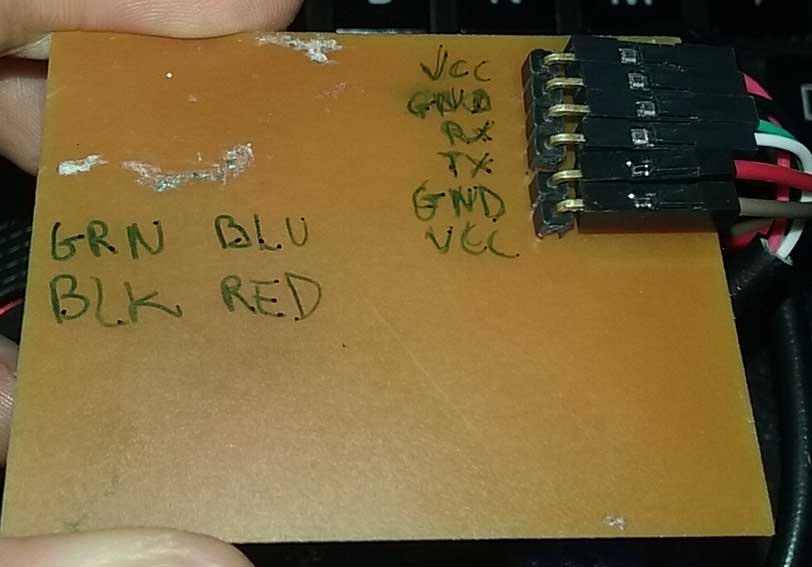
- FTDI RS-232 client and host.
- TX: the host transmit out
- RX: listen
- Input: I use the board that I designed for the Week 11and I programed it with the hello button C code and when the limit switch is pushed it will send a message "d".
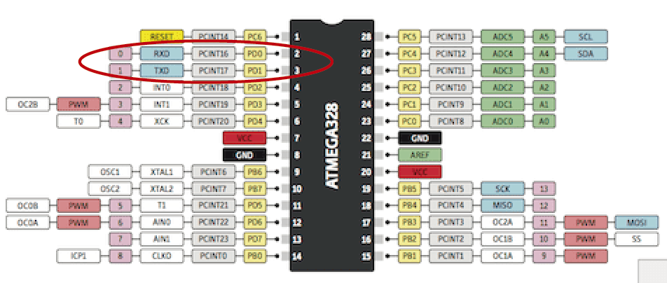
- TX: PA1
- RX: PA0
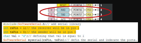
- Output: I use the board that I designed for the Week 07 and use the LED attached to it as an output and when the board read the message "d" the light will turn on. I use the browser in the fabacademy web page and search about LED+Button+networking and I found Eidha Alrashdi who did a a very similar exercise and I use her code as reference to create my own. I realized that she had the same problems as me and after doing the same debugging process she got it.
- TX:PD1
- RX: PD0
- Debugging: At the beginning the wired network doesn't work but after making this changes work well.
- I did the next changes in the code: rx=1 and tx=0
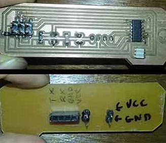
- In the board connection: Connect TX of the "limit switch" board with TX of the "LED" board.
- In the board connection: Connect RX of the "limit switch" board with RX of the "LED" board.
You can download the files:
You can download the file:
SECOND GOAL(BLUETOOTH):
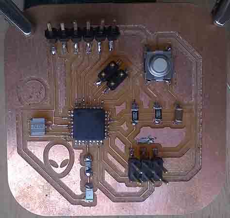
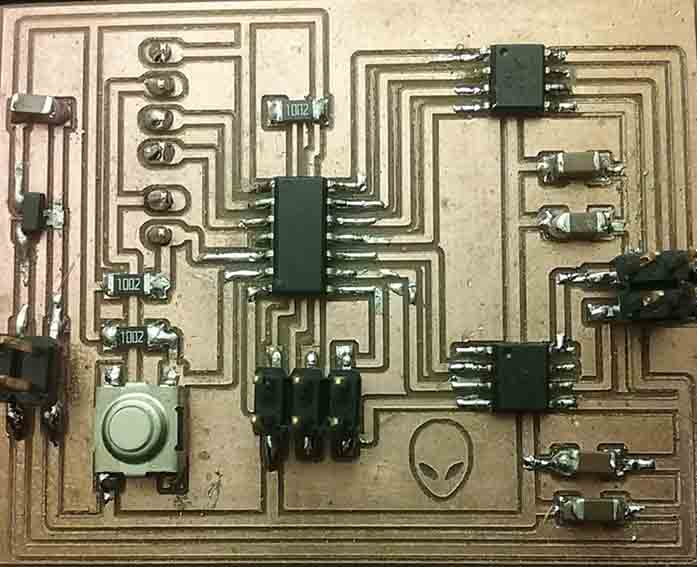
My second goal is to kill two birds with one shot designing a new board that allow me to connect wired or wireless with the same input device board "limit switch" that I created for the Week 11 (mentioned before). For that I want to take advantage of this opportunity of creating a new board and catch up with the week 12 "output devices" and control a stepper motor in relationship with my final project.
Check the design process of this board in the debugging of the week 12.
INPUT / NETWORKING PROGRAMING
This time I just change the message when the switch is push instead "d" now is "0" and when the switch is released instead "u" now is "1".
You can download the file:
OUTPUT / NETWORKING PROGRAMMING
The idea is to activate the stepper motor trough bluetooth using the limit switch. For that I did the next work flow:
I start with Neil code hello stepper bipolar 44 then I review the ftdi echo hello c code that I use in the week 09 which is sending and receiving a message and copy this parts:
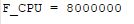
- I'm using in the make file a F_CPU = 8000000 internal so I don't define in the .C code
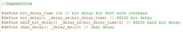
- I change the frequency from 115200 to 9600
- Add RS232 bit delay and RS232 half bit dely
- And the char delay
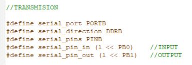
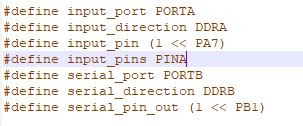
Te next step was to copy the part where define the serial ports and adapt to the right pins of my board:
- PORTB
- DDRB
- PINB
- TX PB1
- RX PB0
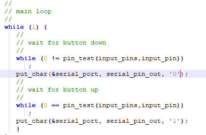
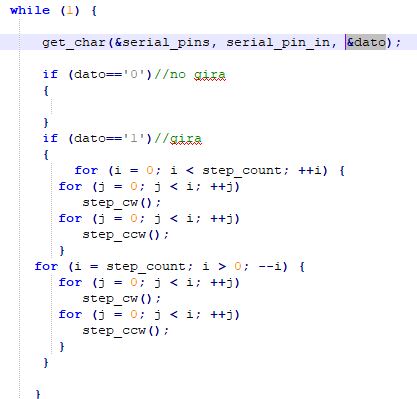
After that I create two "IF" variable inside the main loop and copy the part where is getting a char but instead a of char i put "dato" for that I had to define "static char dato;" above.
I just copy the par that say "get char" because I just want to receive a message if I want to transmit I should copy the part that say "put char".
You can download the file:
HC-05 Wireless Bluetooth Module:
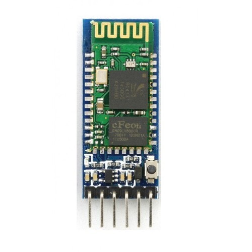
I'm using this device to attach it to my PCB and communicate them it's important to consider that this device is not at the Fab inventory so I should consider this as an extra cost for my final project. This is the work flow that I follow to make the configuration of the module.
To communicate between two bluetooth devices one must be Master and the other a Sleave. Both devices should be configured with the same paswords.
- Before connect the module hold down the button attached to it and keep the button pushed and connected to the PC through a FTDI cable and when the light start blinking slowly means that the module can be programmed.
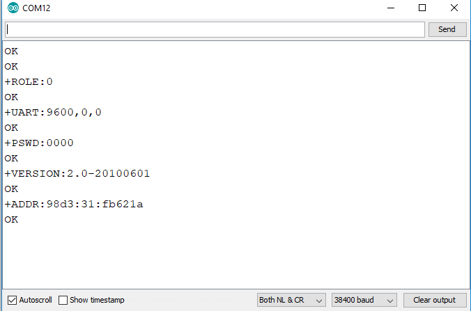
- Open the Arduino Software and the serial monitor and setup to "Both NL & CR" and "38400 baud" (programming frequency).
- Write: "AT" ,its a test command and it should respond "ok".
- Write: "AT+UART=9600" , communication frequency.
- Write: "AT+ROLE=0" , command to put the module in Slave mode.
- Write: "AT+ROLE=1" , command to put the module in Master mode.
- Write: "CMODE=1" , enable the search for available devices.
- Write: "AT+PSWD=0000" , pasword configuration.
- Write: "AT+RESET" to leave the configuration mode.
Check the video!
Group assignment
Goal:
For this assignment I communicate my same input board with the limit switch attached to it to communicate through a simple wired network with the Ale circuit board as an output board created in the week 12 with a RGB LED attached to it. When my switch is push will send the message "d" turning on the red light from the Ale board and when my switch is pull will send the letter "u" turning the green light on.
Output:
We had to edit a previously code made by Ale assigning the "d" and "u" char datums that her board is reading from my board and turn the green and red lights respectively.
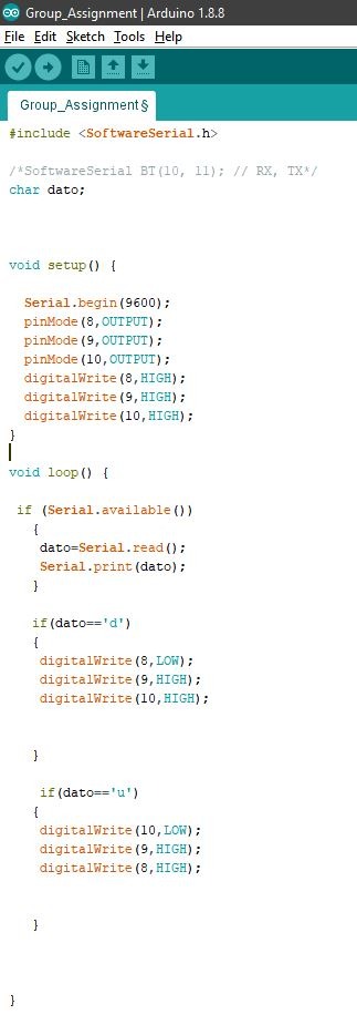
Error: At our fist attempt nothing happens but when we connect TX with the TX and the RX with RX it works! I think the connection in my board is switched.
Check the video below!
Networking and communication Challenge
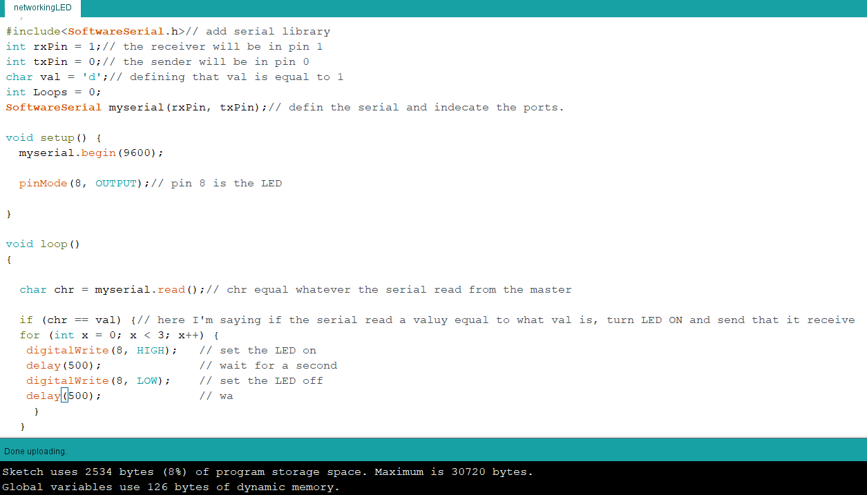
THIRD GOAL: Push the button from one board and the LED attached to the other board blinks three times and turn off.
- Input: When the button is push send the message "d" and when is release the message "u ".
- Program: Define the right pins correspondent to my board.
- Make: Change the frequency to use the internal clock.
- Output: when the board read the message "d" the led attached to it will blink three times and turn off.
- Arduino: I use the reference that I found and fit to my necessities and after all day of test I achieve my goal.
You can download the file:
To achieve my goal I did the next work flow:
For the input I'm using the button attached to my board developed in the week12 debugging and I start from this hello button codes that I use to test my board and I had to make little changes in the codes:
You can download the file:
This par was a little more difficult I start from the code developed in my first goal of this assgnment and then I had to research in google about how to blink a led a number of times and I found this useful link
Check the video!
Conclusion:
Make a simple wired connection was simpler than I was expected I just need to understand the process behind and the code involved in relationship with board design.
I learn a lot making a bluetooth connection between my boards and also programming with C code it's a little hard to understand some parts but I now I understand better the logic of programming.
The bluetooth modules were easy and simple to programing using arduino software.
The difficult part for me was the programming of the main loop and the if variables but with some help now I understand better the way of thinking the programming.