Characterize your lasercutter, making lasercutter test part(s), making test part(s) that vary cutting settings and dimensions.
Individual assignments
Cut something on the vinylcutter
Design, lasercut, and document a parametric press-fit construction kit, which can be assembled in multiple ways. Account for the lasercutter kerf.
For extra credit include elements that aren't flat.
Learning outcomes: Demonstrate and describe parametric 2D modelling processes. Identify and explain processes involved in using the laser cutter. Develop, evaluate and construct the final prototype.
Have you: Explained how you parametrically designed your files. Shown how you made your press-fit kit. Included your design files and photos of your finished project.
Vinyl Cutting Assignment:
There is no specific project that is focussed on this very useful tool. There are a range of ways you might utilise it throughout the programme, or your local instructor may set a specific project. You might make:
stickers
flexible circuit boards
a textured surface/relief pattern
screen print resists/stencils
Ensure that you have used it in some way during this time and met the objectives below.
Learning outcomes: Identify and explain processes involved in using this machine. Design and create the final object.
Have you? Explained how you drew your files. Shown how you made your vinyl project. Included your design files and photos of your finished project.
Group assignment
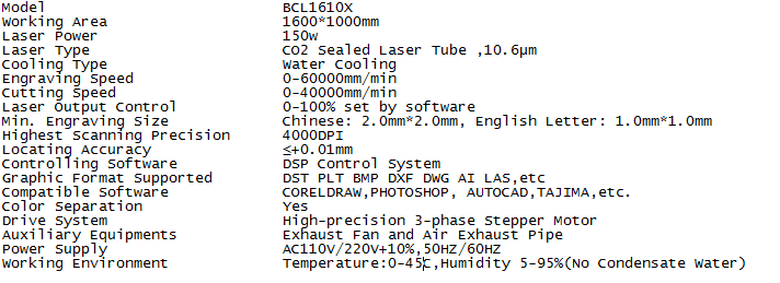
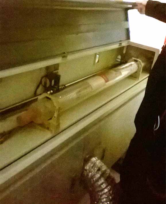
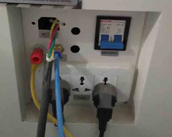
The Laser cutter of our FabLab it's a big one, occupies half of the work area of the room. It consist of different parts and devices, starting from the front side we can find a transparent cover that allows the user to visualize the cutting process on the work table composed of metal rulers to support the work material and can be removed, also we can find the control panel with a screen and many buttons. In the right side we can find two USB ports and four switches to turn on the devices. At the back side it's located the CO2 tube and the main switch.
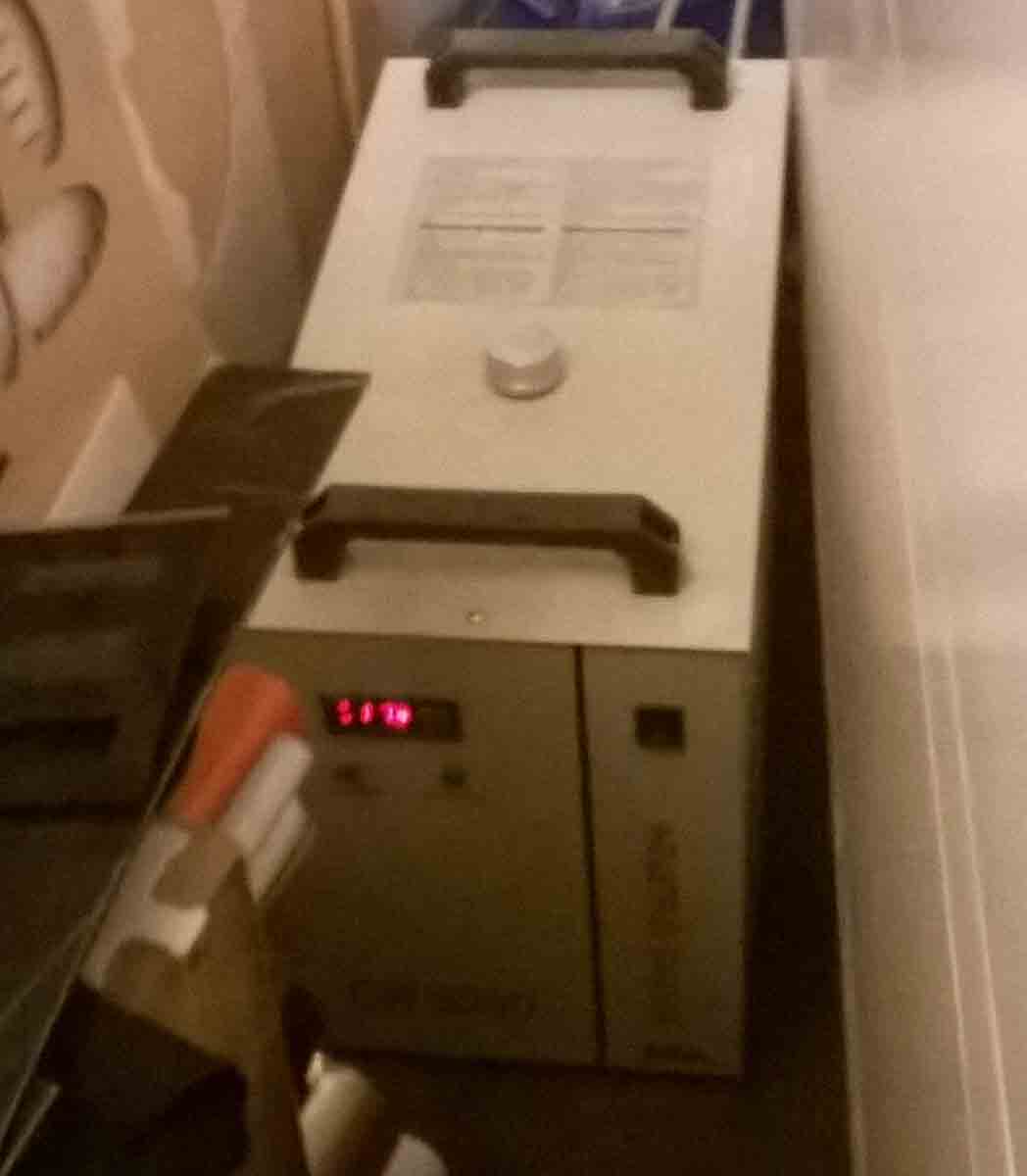
Chiller: use distilled water to cool the machine, it has to be set to work from 20 to 12 Celsius degrees. In our case the chiller doesn't work correctly and we had to check that it doesn't exceed the 27 Celsius degrees.
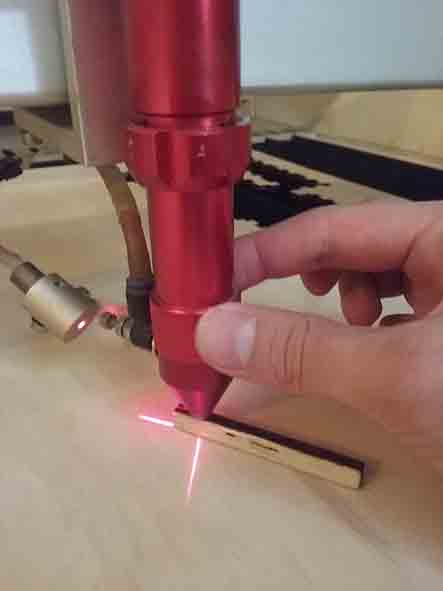
Pull the Emergency button: we always should find it pushed so we had to lift it.
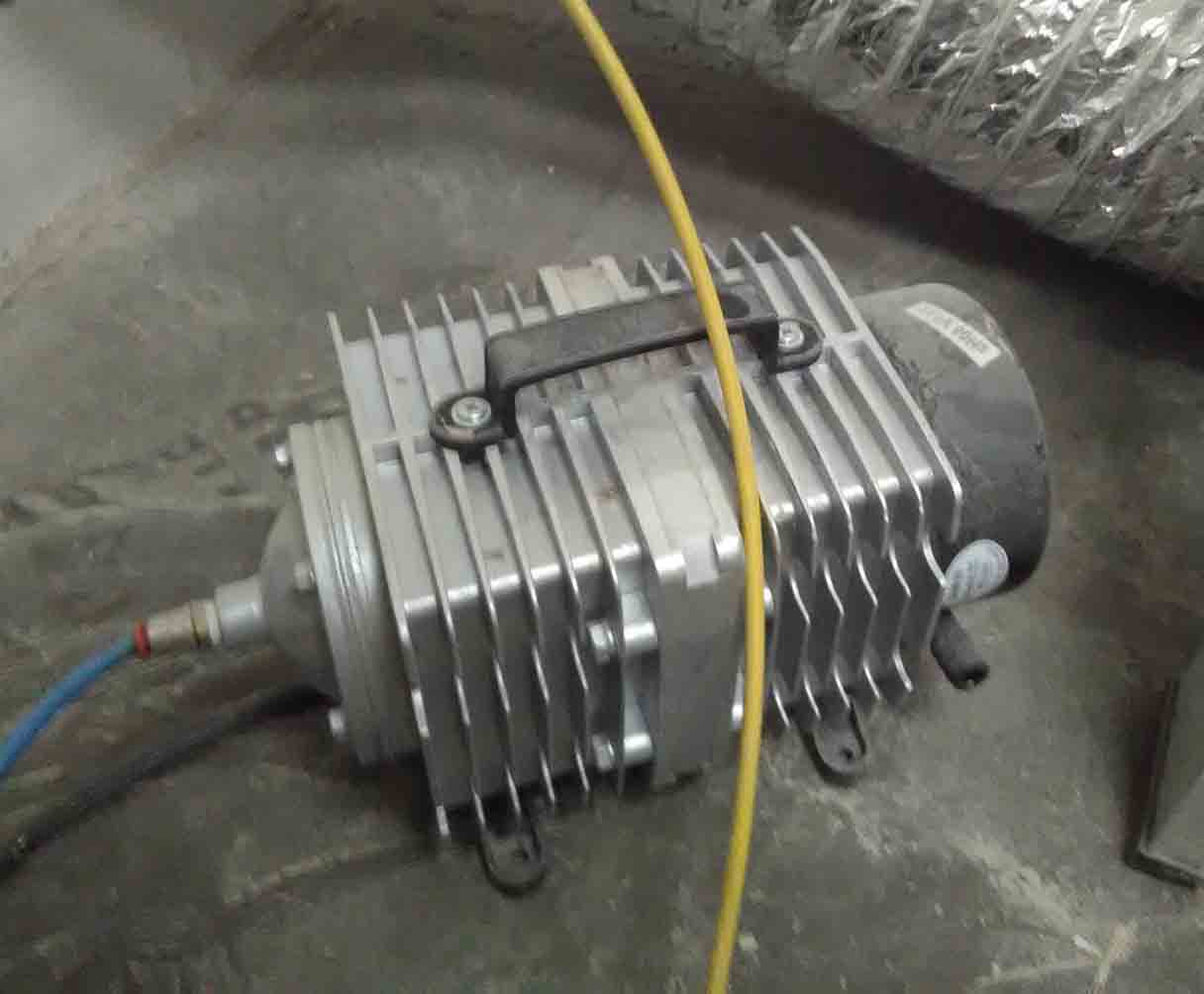
Air pump: allows to extract the gases generated.
Light: illuminates the work area.
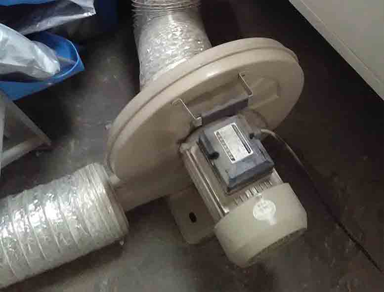
Fan: helps to cool the machine also allows the entry of air into the cutting area preventing the material from catching fire.
Current Knob: It should be positioned to the middle.
Power button: Push it to turn on the machine.
Laser: It should be turn on at the end of the process when we are ready to cut for safety.
Getting ready for the laser cutting:
Load the material: Put it on the work area.
Secure the material: Use the scotch tape to secure it to prevent it from moving and also to put it completely horizontal. And when you are ready close the top lid.
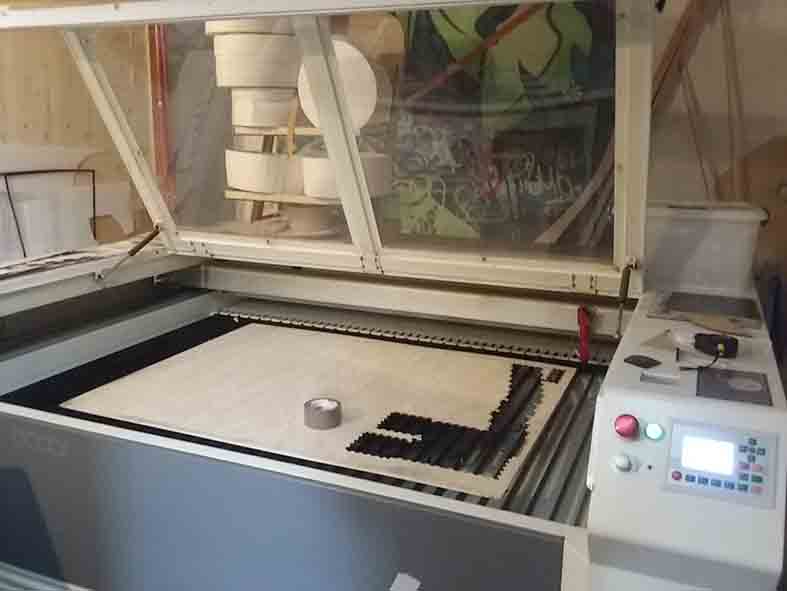
Leveling the laser cutter: We have to consider that the materials have different thickness and because of that we have to level the laser with a 6mm wood piece to reach the desired distance between the laser and the top of the material.
Define the origin: Use the arrows located in the control panel to move the laser in the X and Y axis and define ORIGIN of the cut.
Load the file: we can connect to the machine by three ways:
By USB cable we can connect to the machine with our PC.
We can copy the file from a USB memory to the machine.
We can send the file to the machine from our PC by Wi-Fi.
Once we are ready we can start the process and also we can pause it and after start again.
Finally when the cut ends we have to wait one or two minutes until all the gases are extracted from the work area.
Test parts:
As a team we divide the work in three using different softwares to generate the files:
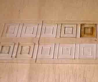
Ale was in charge of the creation of the file with a square shape inside of another square. It allow us to measure the Kerf index comparing the dimensions from the digital file and the real result. For our Laser cutting machine the kerf index is 0.2 mm. At the same time we create and file where we test power and speed for the laser cut to know which is the right one.
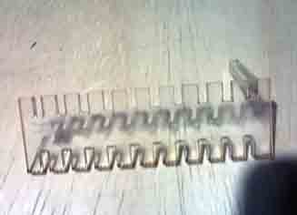
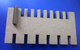
Jorge was in charge to create the file of a comb shape where we constantly increased the space between the joints with a 0.2 mm factor. It allow us to confirm that our index factor is 0.2 mm.
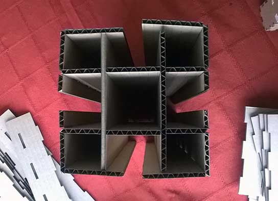
I was in charge of generate the same comb shape to confirm kerf index with a different material than acrylic which was used by Ale and Jorge so we choose cardboard
since Roberto got the right material recommended by Neil, for this I use Freecad to create a parametric file. Then we realized that cardboard is not as good as acrylic to find the kerf because it isn't enough solid, but is an excellent material for other uses.
You can download the file:
Laser Cutting
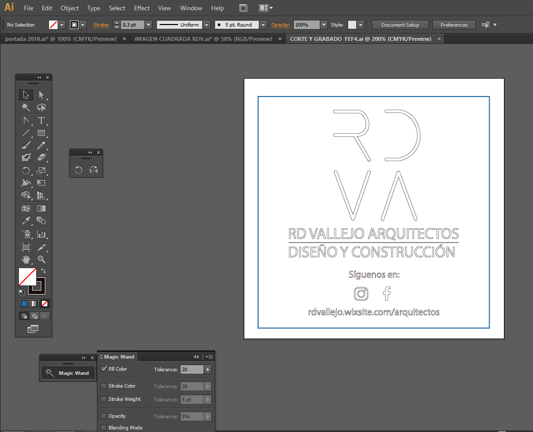
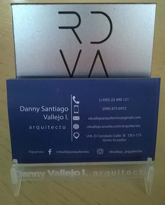
We did a little exercise to learn the process to make a cut where I made a business card holder using a design that I created with Illustrator in the past for my architecture office.
This file has to be vectorized for that I use a new command that I haven't used before called expand and it's located in the object menu.
After that I have to join the different vectors to form single shape, for this I again used a new command that I haven't used before, this command was "Path Finder" shift+m, my instructor gave me that advise.
With the file ready, I export it to DXF format.
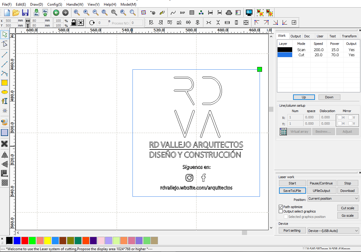
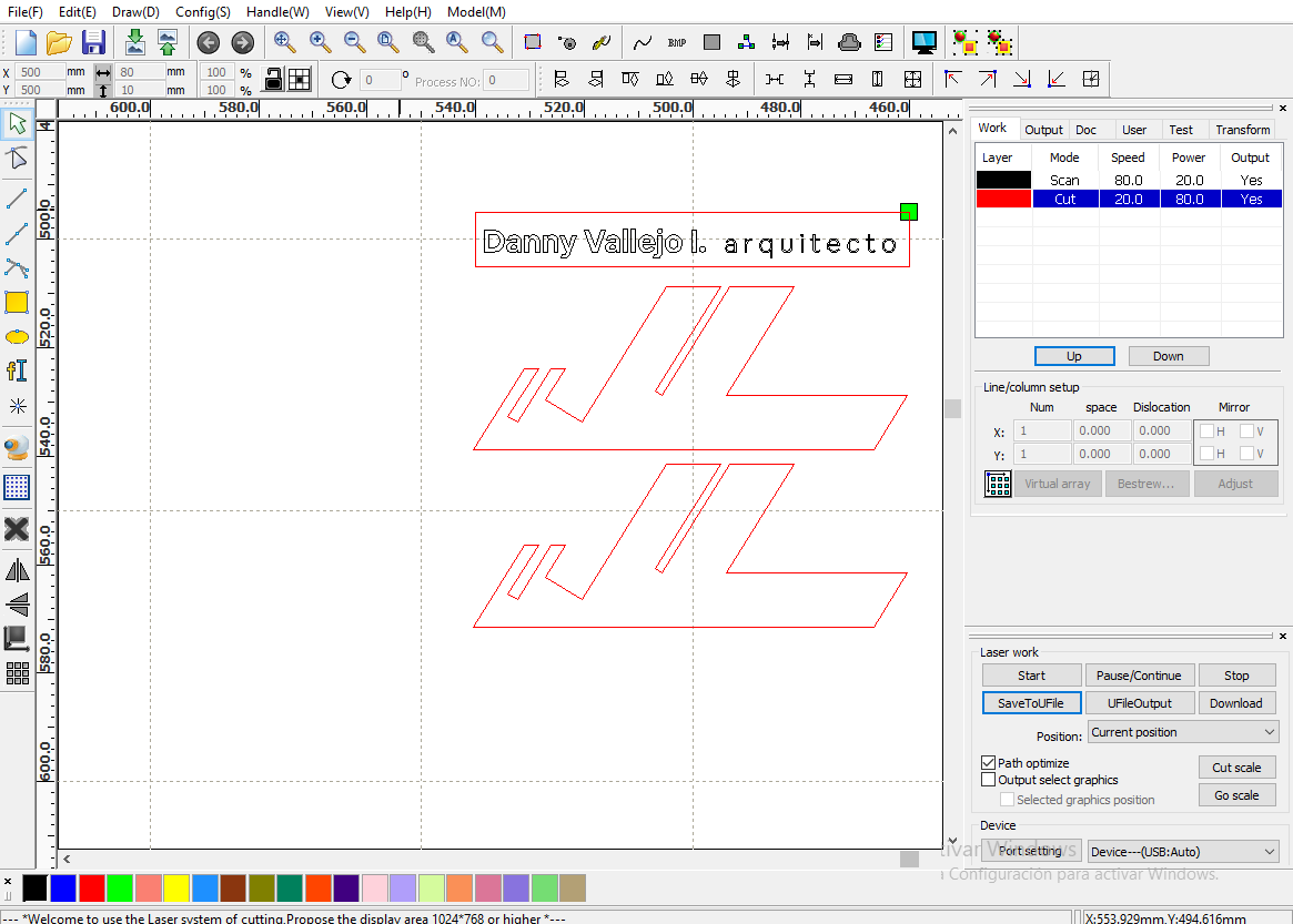
Then I install RDWorks V8 software which is the right one for our laser machine.
The next step was to open the DXF file in the software and set up the speed and power for the different layers that is in relationship with the material, for this time we use black acrylic with a silver surface and the settings were, for the Scan layer speed: 200, power: 15 and for the cut layer were speed: 20, power:70.
Before to start the cut we have to load the material, upload and copy the file to the machine hard disk, select the file we want to cut, locate the origin part that is different from the origin machine, the first one alway will be located to the top-right side, calibrate the height of the laser and finally we are ready to start cut.
For safety we always had to be aware of the cut and once finished wait one or two minutes so that the gases are expelled.
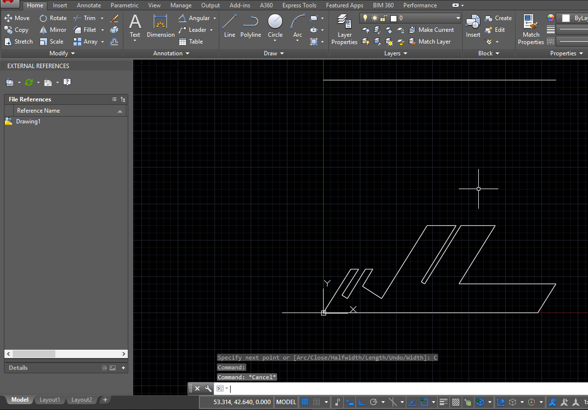
Then I started working in the base of the business card holder for this I used Autocad to create the supports using polylines.
Slideshow 7: Click on the arrow to see the images!
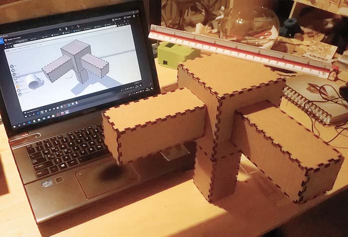
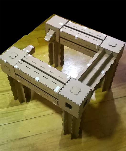
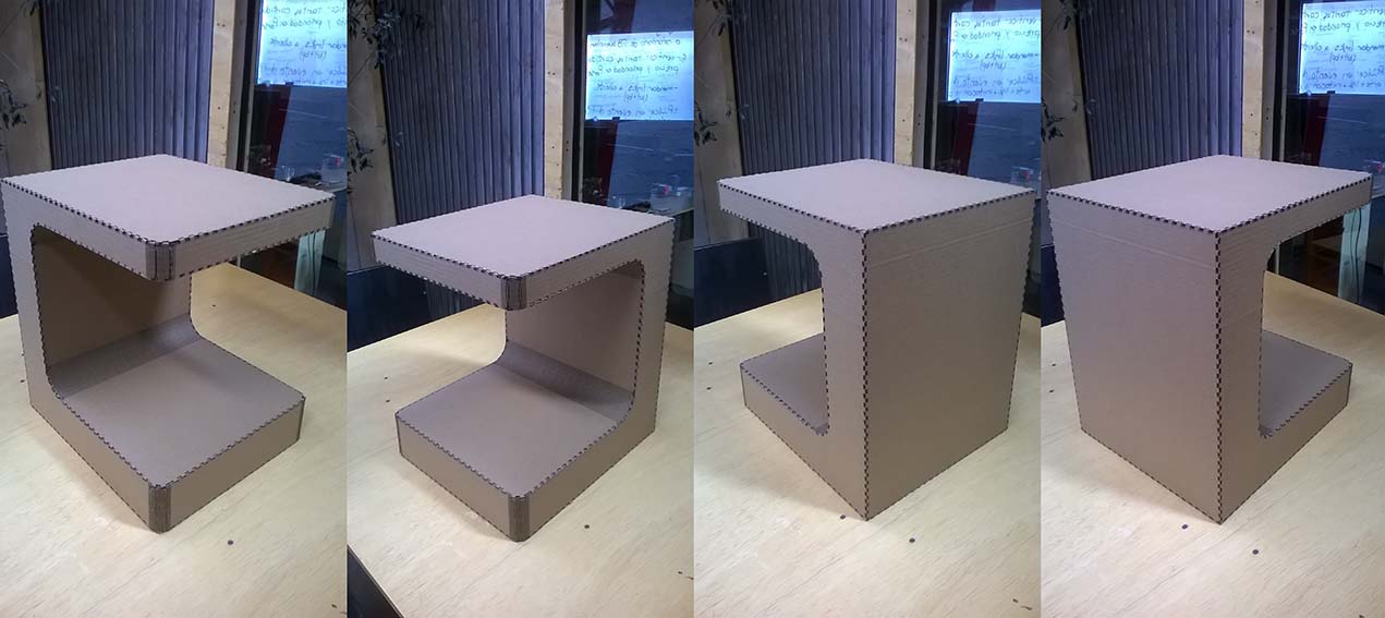
The idea for this assignment was to use the parametric file that I created last week of my 3rd prototype of the structure and create a new one that complement it. The main structure is composed by beams and columns created from the 3rd prototype module.
The new part should be located at the top corners generating a vertex joint which allow join beams and columns to form a closed shape and add more of them in any direction to be assembled in multiple ways.
Process to get the parametric design with Freecad:
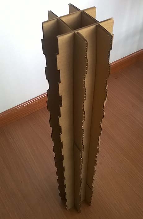
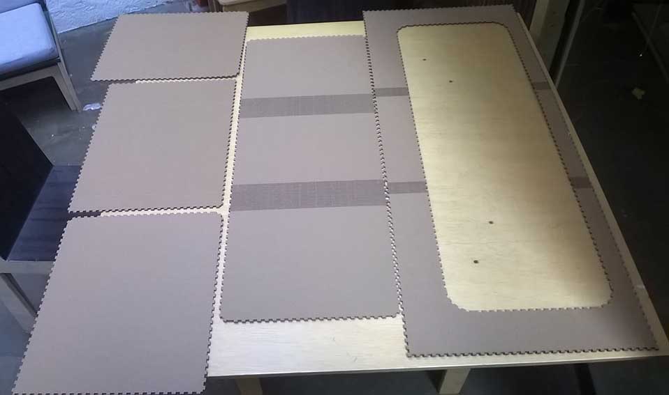
3rd structure prototype cut:
The parametric file was ready for the week 03 so I just had to change the thickness parameter of the material from 9mm to 4 mm and then export as a DXF file and then open in the RDworks V8 software and adjust the settings to cut speed: 50 and power: 60, the right configurations to cut cardboard in our machine.
Then I prepare the machine for the cut and send the file.
Finally I assembly the module.
You can download the files:
Comment: In Freecad, I was drawing the sketches of my modules in the XZ and YZ plane so when I export it to DFX the file was just a line, because the program was watching from above so to fix it I had to enter in the part design workbench and reorient the sketch to the XY plane.
3rd prototype press-fit assemble Conclusion :
The lateral sides of the top module are wrong because the width is smaller than the width of the other modules, it must be checked. The press fit structure work well, and the lateral teeth has to be test checked if works well, for that I should create the corners of the structure and test the desired profile.
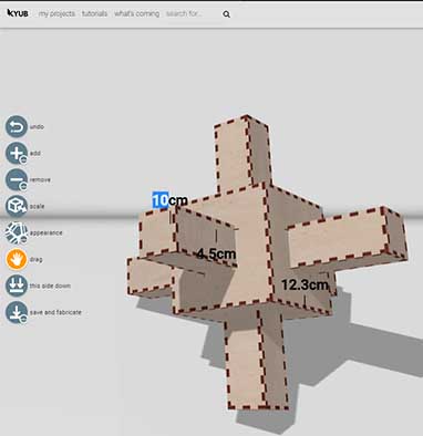
Vertex joint:
For the creation of this part I use Kyub, it's web application witch allow you to design and create 3D forms starting from a cube, and then be laser cut. This shape should be inserted in the holes of the beams and columns to join them and form a closed shape.
KYUB website
I felt curious about KYUB when Andreas from FabLab Erfindergarden spoke about this page and I asked him to give me a code to log in, He very kindly granted it to me.
I started using the software and playing with the user interface, after playing around I found how to use it and it was really simple. The biggest difficult I had was to center the adding cubes, I did it changing the dimensions.
One thing surprise me was that I can put the kerf index for the laser cut machine and the thickness of the material.
You can download the file:
Vertex joint conclusion:
The insertion polyhedron was to big for the beam holes, I was wrong in the calculation of the size of this part. Which must be corrected.
I should create at least 4 Vertex joints to complete the shape.
The union between the cube an the insertion polyhedrons resist in card board, but is to week for the final project prototype so the Vertex joint should be a single part to resist the weight of the beams.
Assembly between columns and beams through vertex joint.
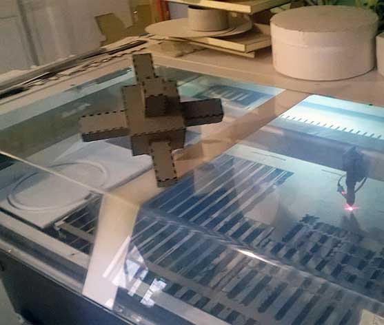
I fixed the errors of my previous files, first the measures of the vertex joint, after that I add a joint to each face of the cube in order to could be assemble in multiple ways using the web application Kyub editing my last design, afther that I fix the width of the top module editing the last Freecad file, finally I send them to cut at the laser machine.
I only reach to cut half of my press-fit kit because when I started cutting the second part, the laser head hit with some acrylic that was stored inside of the machine and stop cutting, I think the problem was about the lens it could be moved on the impact.
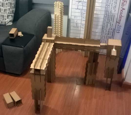
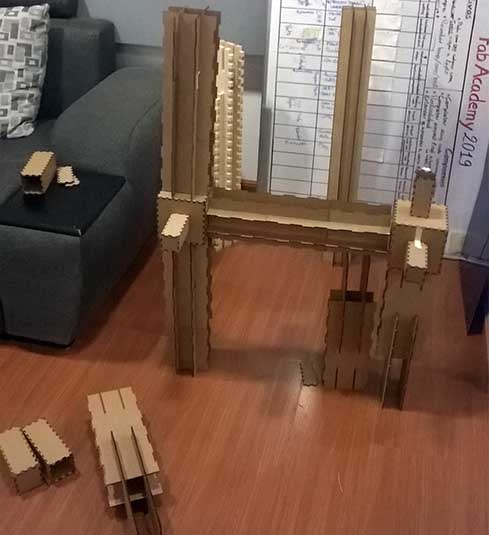
Finally I assemble the parts of my press-fit kit getting the desired result
You can download the file:
Press-fit kit conclusion:
I realized that the dimension of the insertion polyhedrons are 0.4 mm larger of the digital design, that's because when the software asked me to put the kerf index I enter 0.2mm, for this time it wasn't a problem but if I had worked with other material such as wood it would not have fit.
The design of the module corners is something that is still pending.
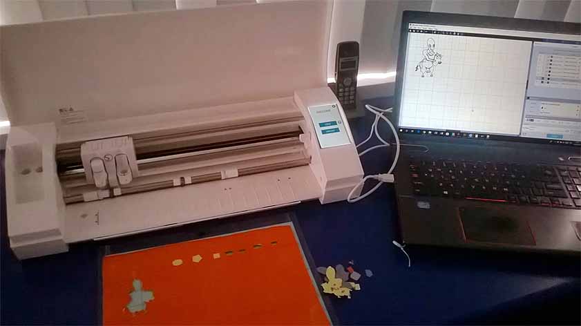
Vinyl cutter
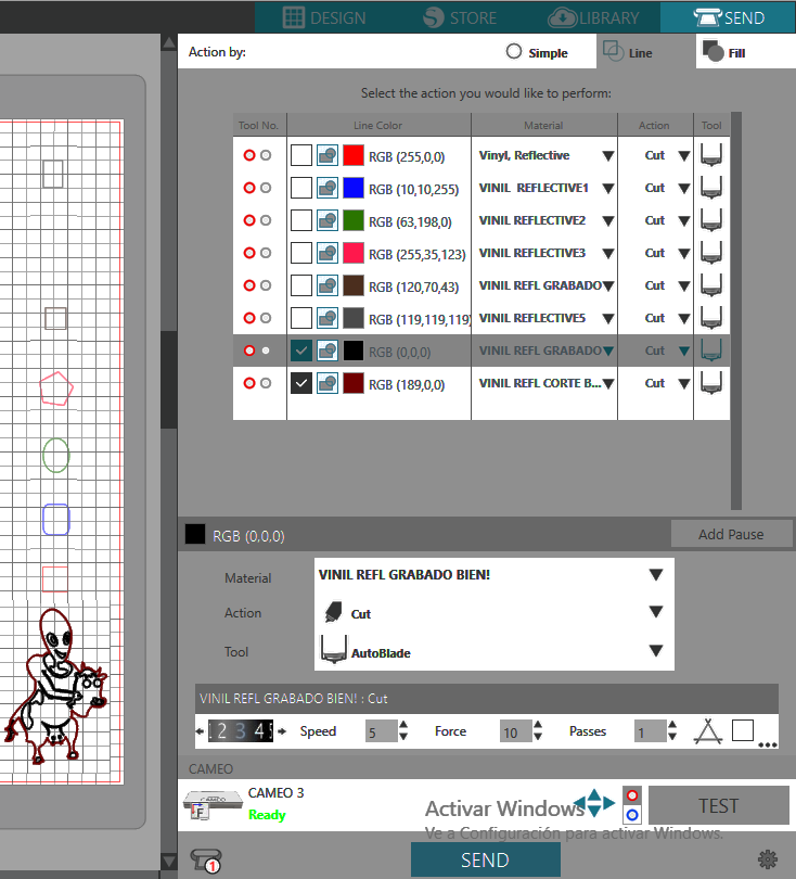
We use SILHOUETTE CAMEO a desktop cutting machine. It uses a small blade to cut many materials.
I started reading the manual and doing the tutorials that are included in the machine to know the essentials steps like adjusting the blade, adjusting the rollers, leading the mat and making our first cut. I found a really useful information about characteristics, tutorials, etc here.
After that I download install the software to my PC.
Then I drew some shapes with different colors to be read as different layers and assigning different material settings to each one starting from the preset vinyl-reflective. This process required a lot of patience to find the right settings to cut the vinyl.
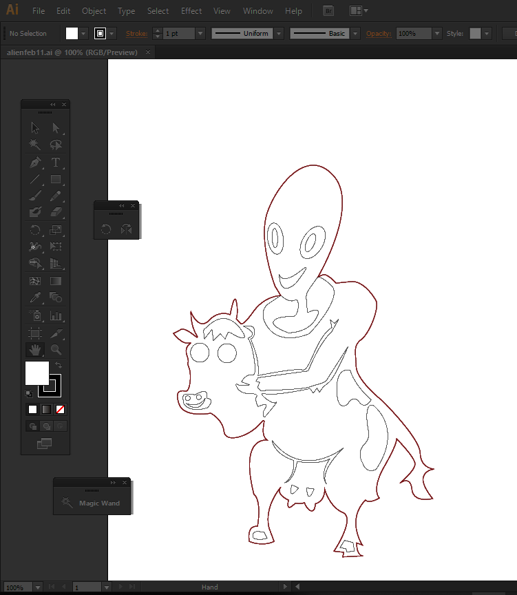
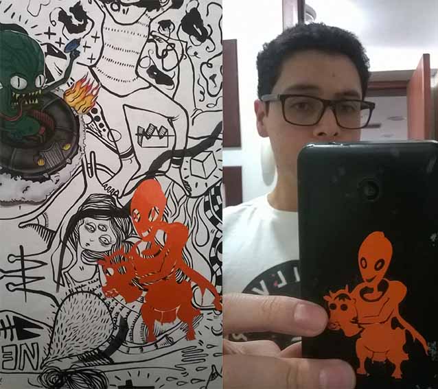
After having found the right material settings for my vinyl, I load my Alien design created the last week03 with Inkscape and then modified with Illustrator in which I have more experience I change the software because I started to getting out of time.
Finally I send the file to cut, the first had little issues, for some reason the final shape to be cut moves a little to the top and it was difficult paste and get the desire shape, because of that I did another cut increasing the size of the shape and checking the design and settings it's okay, the result was pretty much like the first one I don't know certainly what happen but I suspect the material slipped.
Slideshow 8: Click on the arrow to see the images!
For extra credit include elements that aren't flat.
As an extra activity at Fablab ZIO we make an agreement to pay part of my fabacademy bill. The idea is to create an orbital Shaker which has a circular motion with a slow speed. The name that Roberto gave the machine is Bio-shaker.
The shape has a round corners and the only idea that occurred to me was to use the web application Kyub that I used before for the creation of my vertex joints. This application allows me to create round corners in a very easy way and after laser cut.
Whatch the work flow used in the design at the web application Kyub:
Check this photo and the file attached below is so crazy how we can create things using softwares like this is really easy and any one can use it.
Conclusion:
Group assignment: This exercise allow us to distinguish the difference in the dimensions between the digital design and the digital fabrication in the real world. Also that we have to make some tests to find the right settings for each material and for the desired finish.
Laser Cutting: All the machines are different and each of them must be configured and tested to know the right settings additionally the thickness of the material is a very important aspect to consider in the design.
Parametric press-fit construction: The main structure of my final project is conformed by press-fit modules which assembled form columns and beams, which are joined by the vertex joints which start from a cube with insertion polyhedrons that could be placed at any face and and in order to get a closed shape or add more parts to form a bigger shape horizontally or vertically.
Vinyl cutter: Is a very useful tool that allow us to cut complex shapes and designs. I really enjoy cutting my alien design and I would like to use for electronic production some day.
