Characterize the design rules for your PCB production process
Individual assignments
Make an in-circuit programmer by milling the PCB, program it, then optionally, trying other processes.
Learning outcomes: Described the process of milling, stuffing, de-bugging and programming. Demonstrate correct workflows and identify areas for improvement if required.
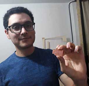
Have you: Shown how you made and programmed the board.Explained any problems and how you fixed them. Included a "hero shot" of your board.
Group assignment
MODS
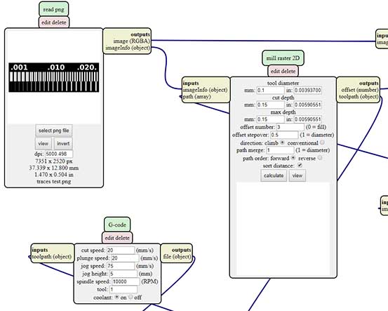
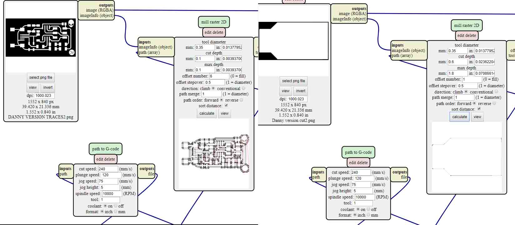
The fist thing we start doing after the Neil's class was to understand mods web application and how it work and the different parameters involved for the program G-code mill 2D PNG which has the following parameters:
Tool diameter: diameter of the milling cutter.
Cut depth: how much goes down the milling cutter.
Max depht: the maximum limit at which the milling cutter will go down.
Offset number: number of steps in which the milling machine will remove the unwanted material.
Offset stepover: percentage of the milling machine cutter diameter will remove each step.
Direction: climb
Path merge:
Path order:
Calculate: this button generate and automatically download the G code file for the CNC machine.
The second step was to review the G-code node:
Cut speed: Speed from one point to another
plunge speed: how long it takes to go up and down
jog speed:
jog height:
spindle speed: turning speed.
tool:1
coolant:on
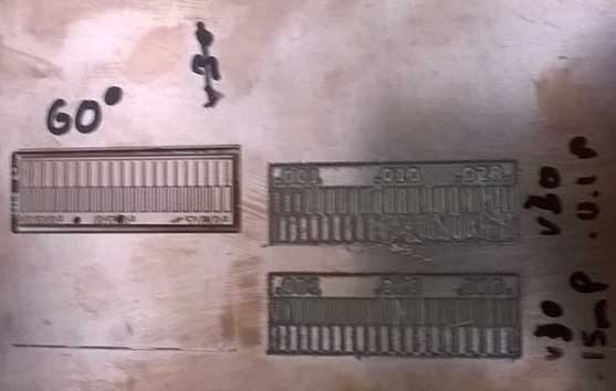
After that we downloaded the Traces and the Interior PNG files to test the precision and configuration of our machine.
Characterizing the design rules for G-Code mill 2D png software.
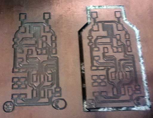
For our first attempt we use a 60 degrees milling cutter and previously tested parameters by Alex and the result was amazing our machine had a really good precision, we were wrong in the cut file because the machine cut from the inside instead of the exterior and some parts of the characters disappear. The parameters used were: Tool diameter 1/64 for tracing, 1/32 for cutting (around 0.4mm and 0.8mm respectively); Cut depth for tracing 0.5 and for cutting 0.8 (with max depth 2.8) ; Offset number for tracing 3 and for cutting 1 ; Offset stepover 0.5
For the second attempt we change to a 30 degrees milling cutter using almost the same parameters and the result radically change it was pretty bad.
For the third attempt we use 30 degrees milling cutter and change some of the parameters and the result wasn't the desired.
Characterizing the design rules for PCB.
The PCB layout and design is a specialist skill requiring knowledge of not only of the PCB design software and PCB CAD system, but also a variety of standards and techniques used to ensure that the basic circuit design is successfully transferred to an overall printed circuit board that can be manufactured in an electronics circuit manufacturing environment.
I found two links about the basics of PCB design guidleines and the points to watch during PCB design and printed circuit board layout: English and Spanish.
CAM
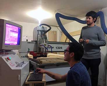
CNC machine:
Safety: pick up your hair, use the appropriate shoes, take off hanging accessories and jacket, stay away from the right side of the machine because the space is vary small on that side.
We always find in zero point the machine and we should always leave it there.
Switch on transformer.
Turn on the PC.
Open the software Linux CNC
Turn on the CNC machine.
Turn on Emergency button software.
Configure home of zero points for x,y,z.
Regulate offset.
Load file in AutoLevel software to generate the G-code for our specific machine.
Put the sensor on the surface material.
Execute the file step by step.
If it's too high we have to redefine z
When it gives the jump to the middle I can give play button.
The machine calculate the eight points.
Remove sensor.
Insert tool.
Wait for the engine revolutionize.
I can give play button.
Browse for probe log in AutoLevel if I want to cut with the last information previously generated.
Individual assignment
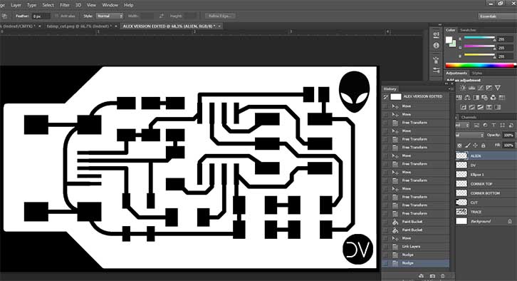
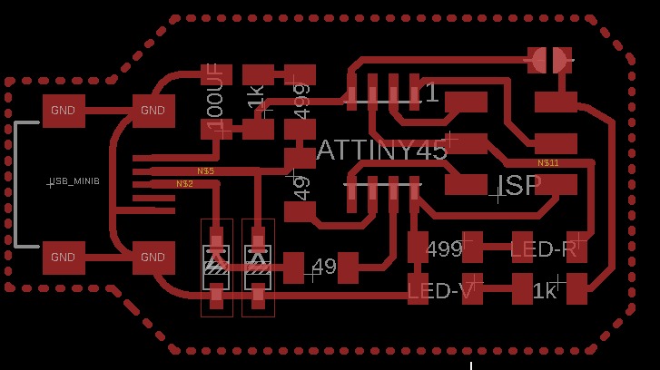
We have decided to start from the Alex version developed in the FabAcademy 2018 class at FabLab ZOI.
For that I download the PNG Traces file and the board outline file located in his page.
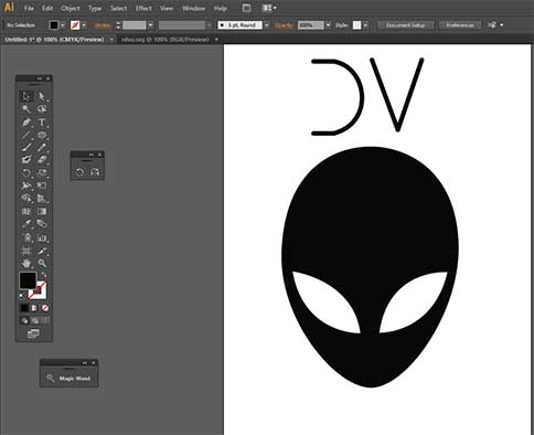
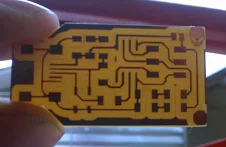
We decided to customize the PNG file adding something to the Alex version design, in my case I add an alien face and my initials using Illustrator and Photoshop it was a little difficult hack the original PNG file because the image can't be modified so I had to start in a new file and copy it.
I uploaded the PNG to MODS and enter the parameters used in our first test.
First attempt: the tracks were too small and the reason for this was the tool diameter was set in 0.2 mm
Second attempt: then I change the tool diameter to 0.1 and the result was better, even though the result could be better, I started to run out time so I decided to keep this PCB.
Inventory:We did a review of how the micro-components are stored, because its very important to have them in order to be able to find them easily.
Micro-components:
1 x ATtiny45 or ATtiny85
2 x 1 Kilo ohm resistors
2 x 499 Ohm resistors
2 x 49 Ohm resistors
2 x 3.3v Zener diodes
1 x red LED
1 x green LED
1 x 100nF capacitor
1 x pins of 2x3 pins
1 x micro USB connector
1 x programmer cable
2 x 3 pins
We had a small class about solder and practice how to do it with the help of our instructor Roberto and David, who actually collaborate trying to make it reality the BioAcademy in FabLabZoi. In this class we use the basic tools like a welding station, braid, hot air, tweezers, third hand, PCB and paste.
Slideshow 9: Click on the arrow to see the images!
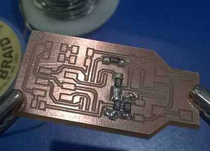
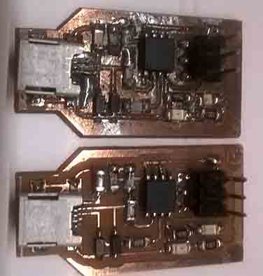
Welding the Alex version PCB was a real challenge because of the size.
I lose three tracks while I was welding, the solution was to weld a copper cable that serves as a replacement for the tracks.
While welding I spread a lot of tin solder, the solution for this was to use the desoldering wire, a trick that I learned was to soak it in the pasta and then warm it up with the soldering iron.
With the help of a multimeter I could verify that my components are connected correctly with each other. Also was very useful to know which components shouldn't be connected.
My PCB couldn't be read because some of the components were connected to the outside of the board, the solution for that was to remove the sold that was making contact with the outside of the plate. After that work well! :)
Slideshow 10: Click on the arrow to see the images!
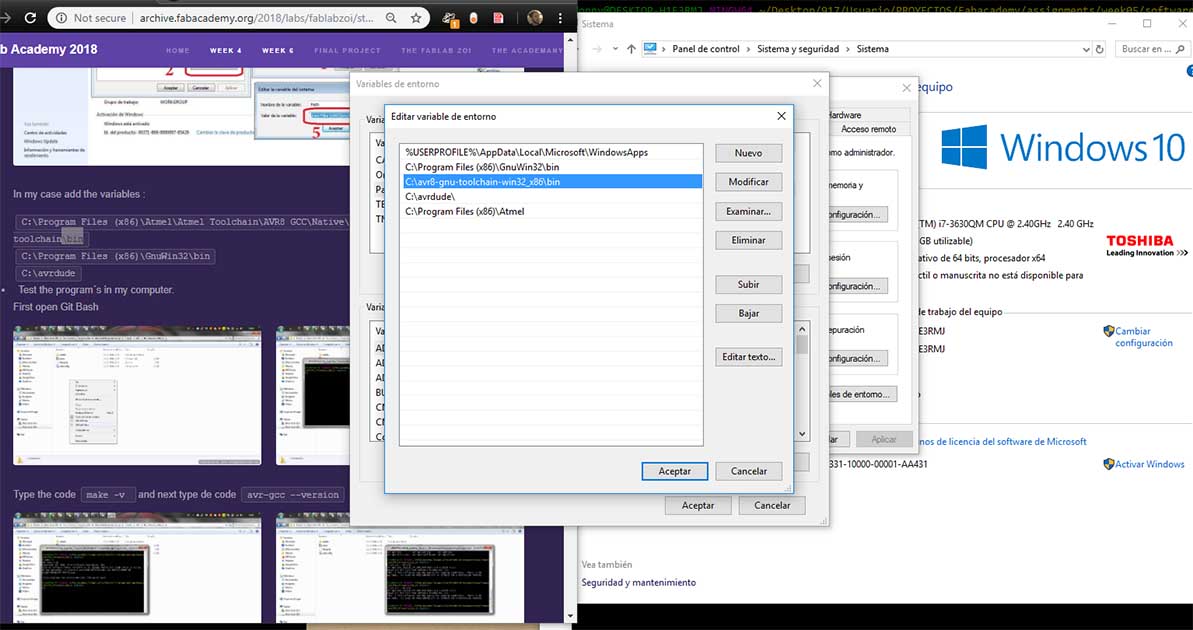
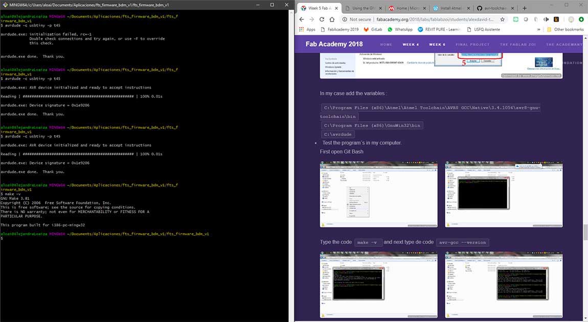
Atmel GNU Toolchain (The file from the link from Alex website is not there any more and the updated versions don't work for me so I use AVR 8-bit Toolchain v3.62-windows).
Add the paths of the location of the installed softwares.
add "\bin" at the end of the toolchin and gnu file path
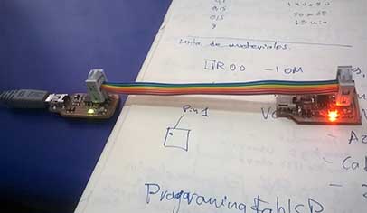
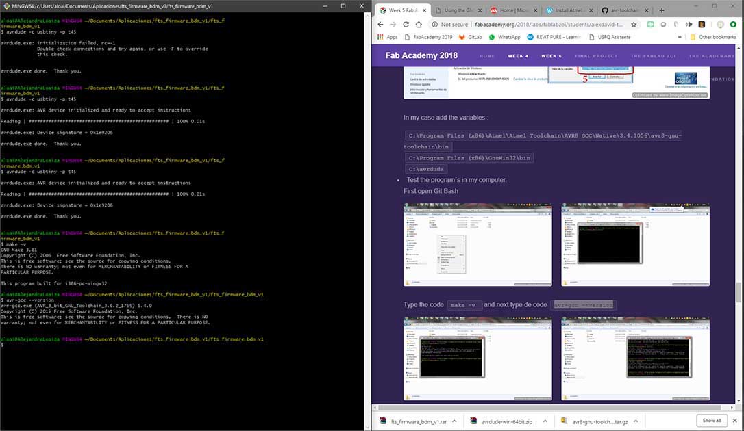
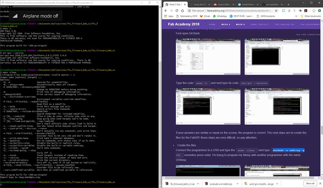
Open the unzip folder where you installed "fts_firmware_bdm_v1" and meke "git bash here", then Connect the programmer to a USB and type the next codes:
make -v
avr-gcc --version
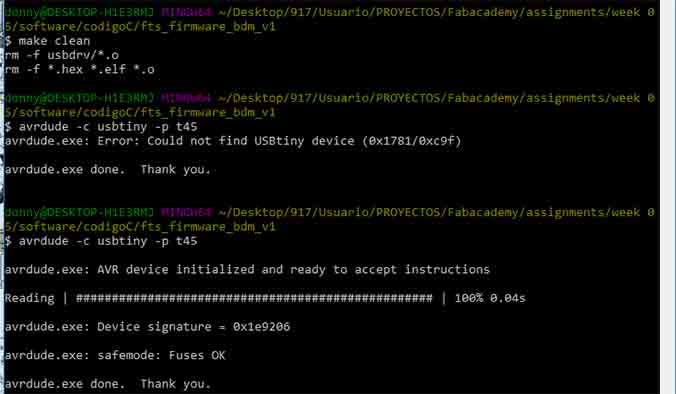
make -clean
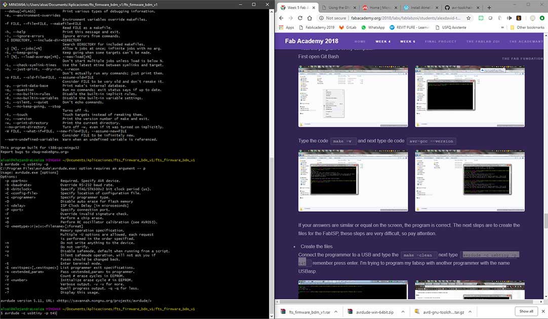
avrdude -c usbtiny -p t45
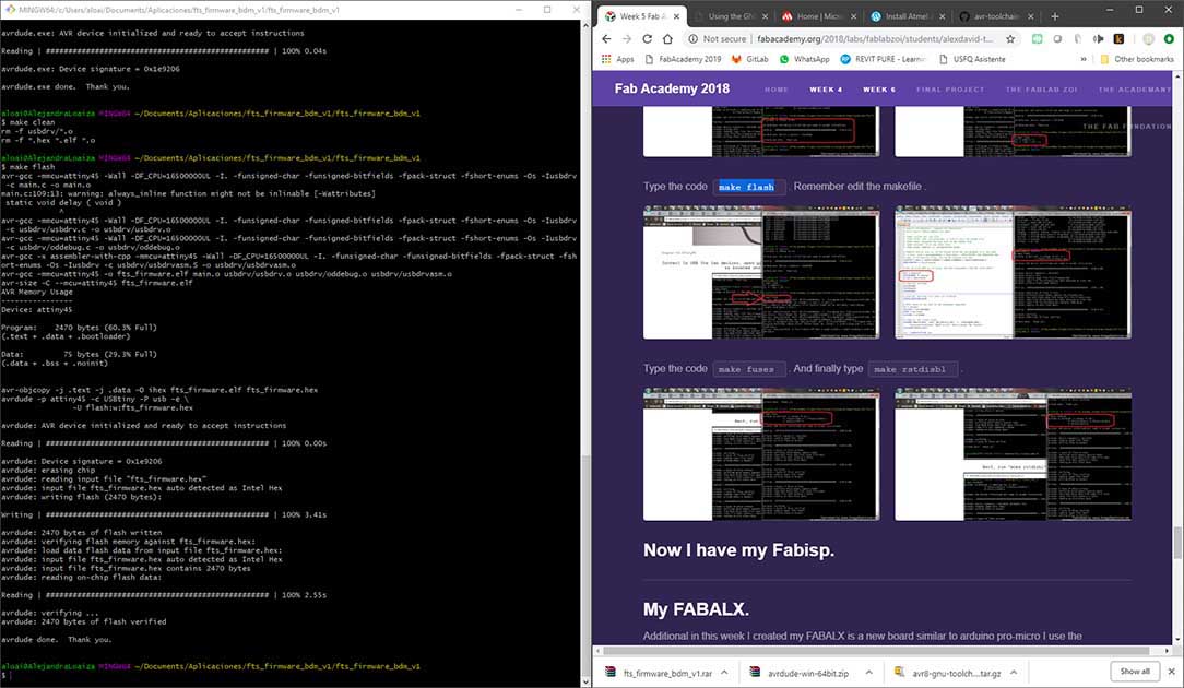
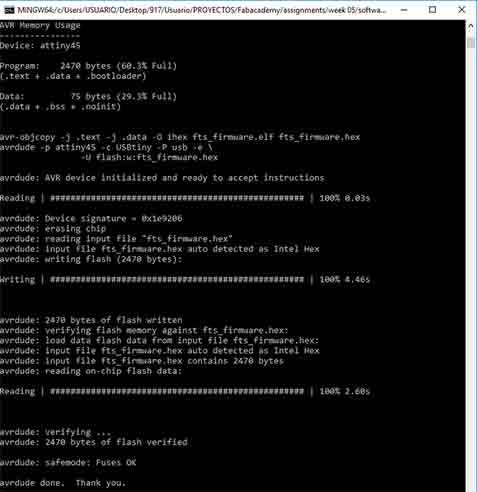
make flash
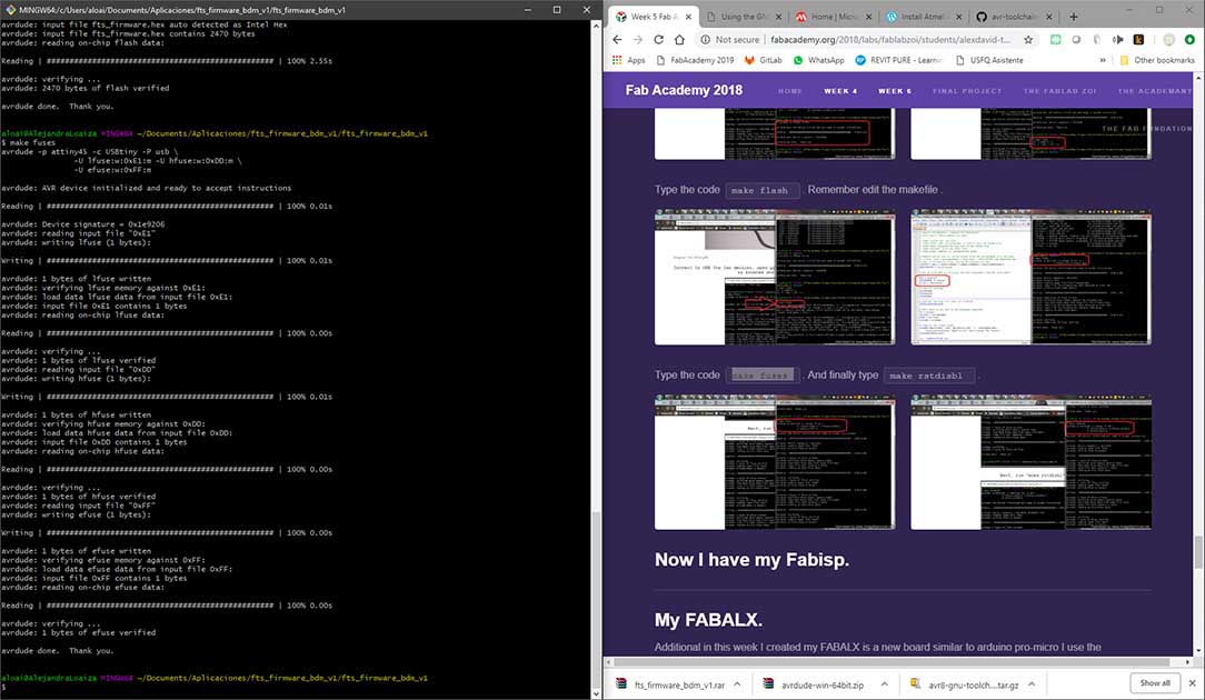
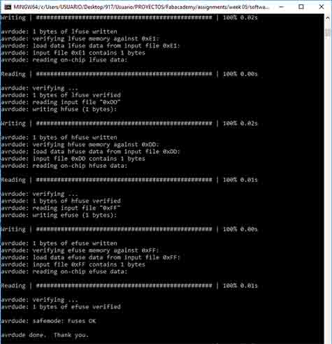
make fuses
make rstdisbl
Problem: in the end I managed to program my plate but the last command I entered "make rstdisbl" block the PCB and it could not be read anymore, the solution for this could be desoldering the microprocessor and put a new one.
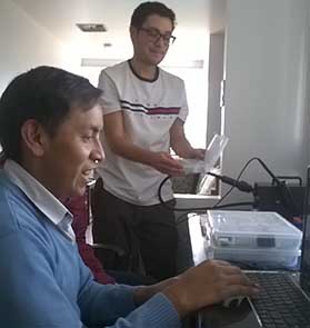
Because we were running out of time I program my PCB in Ale's PC.
Slideshow 11: Click on the arrow to see the images!
I had to make a new programmer since the first one stops working when sending the last command, for that I did the next process:
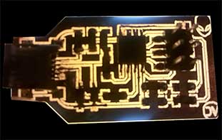
First I had to create a new PCB. I use the same traces and cut png files that I created before. I uploaded to Mods in the G-code and put the settings previously tested for Alex. This time I increase the offset number from 3 to 6 because the las time when I solder the components I joined some tracks that should not be joined. Then I had to prepare "autoleveled" G-code, for that I just open the AutoLeveller, point it to the G-code generated in MODS, and hit "go". I got my G-Code with the autoleveler included. Finally I opened it in LinuxCNC to proceed with the milling cut.
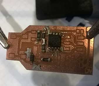
Then I solder the micro components again, this time I star soldering the microprocessor and the USB for that I put a little solder first in each tiny leg and then putting in the right position to solder to the board, this time I did better and no track came out.
Finally I had to program the programmer again and this time I did it in my PC, for that I did the next process:
I already had the, Atmel GNU Toolchain, GNU Make, AVRdude, USB Tiny Driver and the Firmware softwares installed on my PC.
I followed the Alex version tutorial again to program my board and this time the installation was successful.
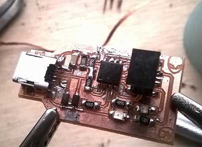
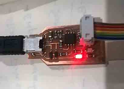
When I try to program with my programmer an Error appear "the "USB Device Not Recognized". I realized that I solder wrong one resistor and some tiny legs of the usb, after correcting this the programmer work very well! :)
Slideshow 14: Click on the arrow to see the images!
I really enjoy this assignment, it was really exiting to learn how a PCB works and all the process involved in electronic production. I hope I can repair my programmer.
The final code "make rstdisbl" was necessary to prevent the board auto reset when is conected to the PC. On my second attempt I write the final code and work well.
I am not 100% sure about what happend in my fist attempt but I suspect that was something related to that I use Ale's PC, because when I did the same process on mine every thing work well.
