Week 9: Embedded programming
With programming languages it is a bit same as with opinions. Everyone has its own. You may also have more than one opinion. When I'm considering this sentence for a bit longer I remind a funny sentence. We have this saying, if there are two Poles, there is at least 3 opinions. Probably none of them is also right, just a side note.
The good news are that we can use board from previous week, as it has some additional features. Work smart not much! The bad news are... there are no really bad news.
Group Assignment
Whole group, yay!
Under a bit enigmatic sentence: "compare the performance and development workflows for other architectures" simple meaning is hiding. We just need to test couple programming environments, programmers or languages. So far we were utilizing command line to compile, make files and upload the program onto the chip, but there are plenty other ways to do it.
Using Arduino IDE we were able to test two of following programmers:
- STM32 Nucleo-64 development board with STM32F401RE MCU
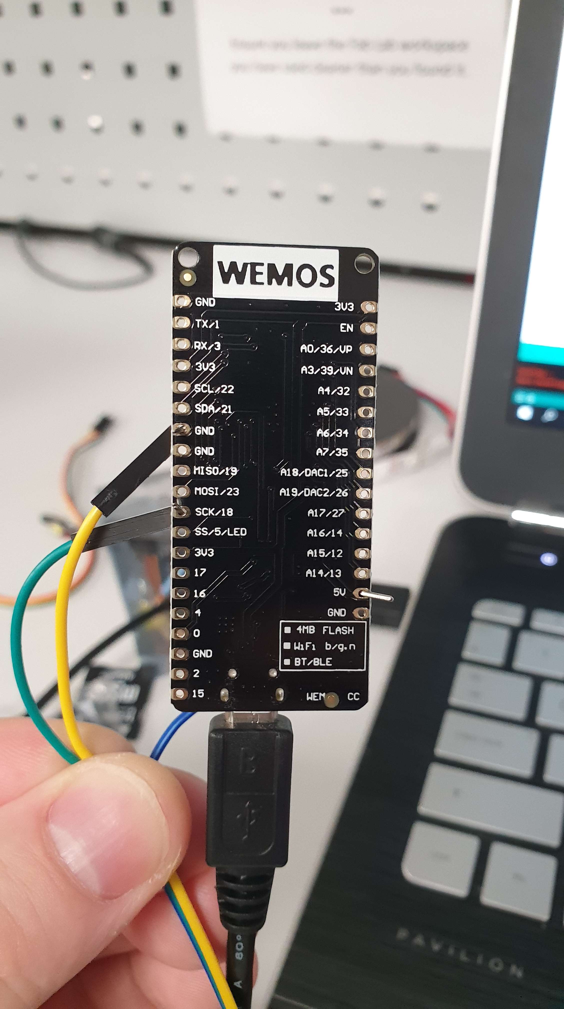
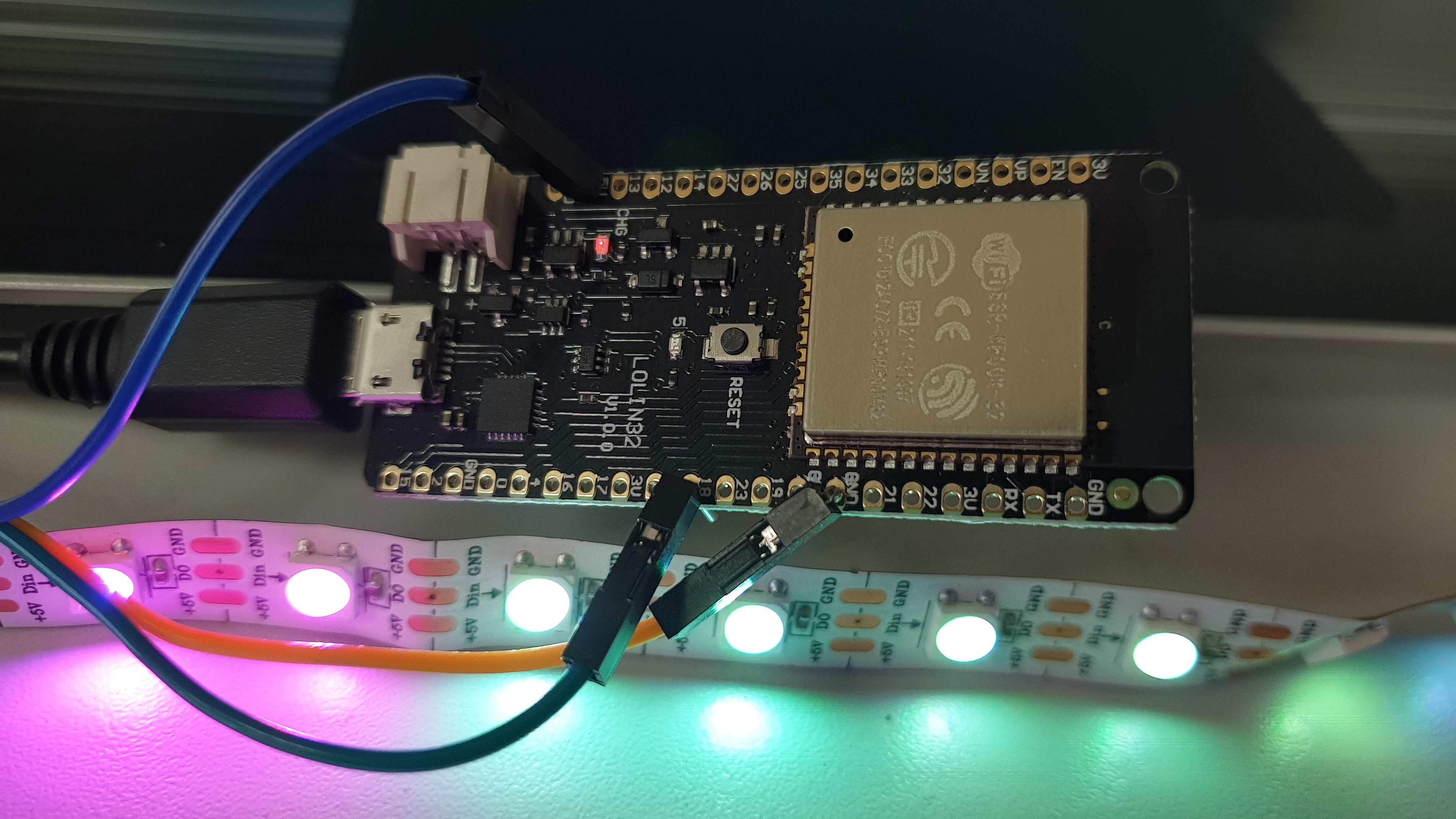
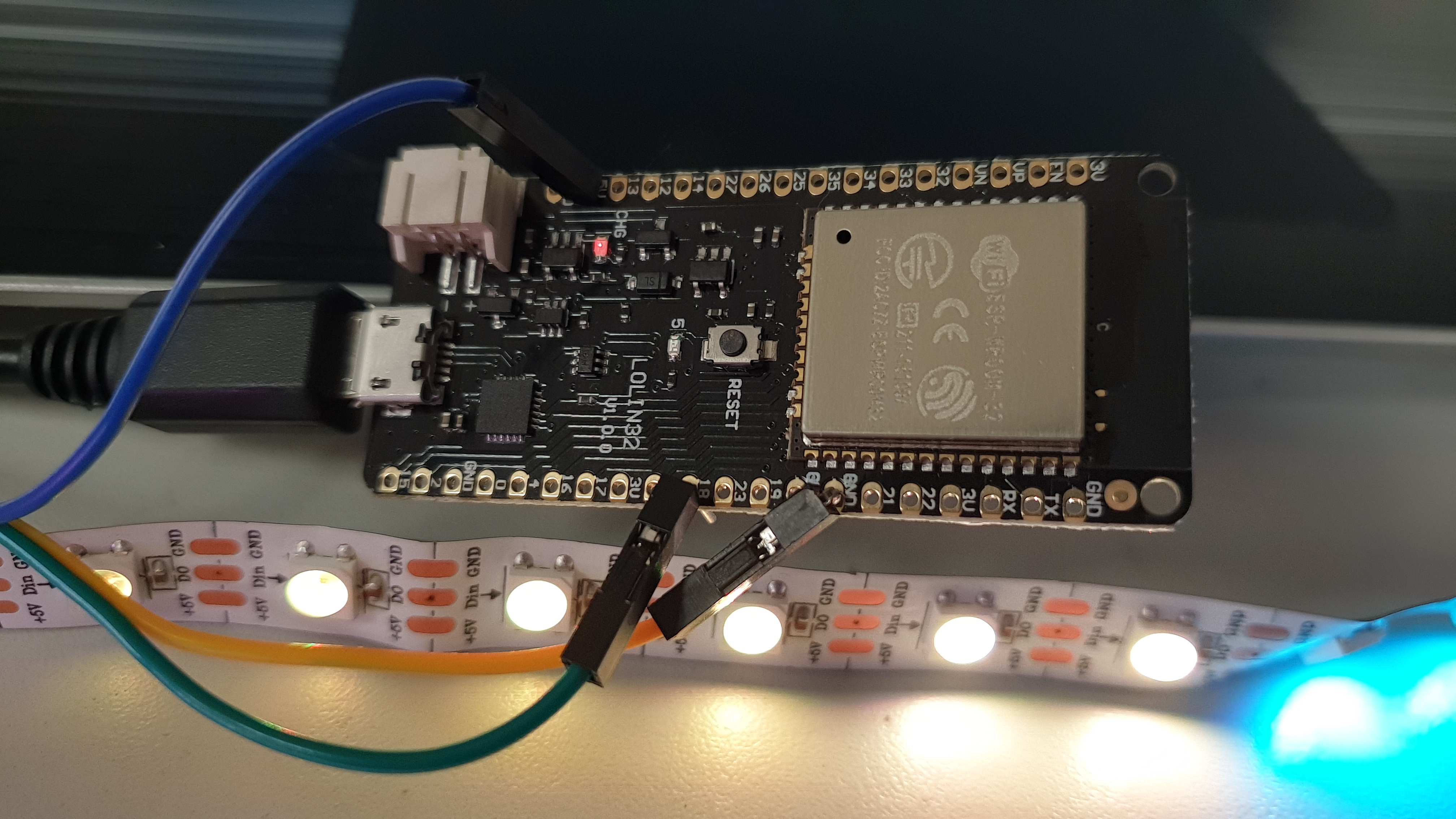
- ESP32 LOLIN32 development board
It is also possible to adjust Arduino IDE with our previously made programmer (USBTinyISP). I just discovered it is much simpler than in Atmel Studio. Alright, first of all some documentation that we were using during our work:
The procedure is very similar for each one of previously mentioned programmers (STM32, ESP32, USBTiny). Those can be easily followed using previously mentioned links. However, just for the sake of record, exemplary procedure is shown below. As far as I remember, we didn't experience any major issues. I think the only one was rather slow speed of download. In general as we could choose similar programmers to previous year students, for troubleshooting purposes we were using our co-students repositories.
Alright, I remember I said that the procedure may be found "below" but before we start, some theory on the chips and the instructions. Let's begin with some comparison of RISK - Reduced Instruction Set Computing and CISC - Complex Instruction Set Computing architectures. All of our programmers were based on RISC as it has certain advantages for our purposes. I believe it is easier to understand after familiarizing with following table:
Was developed in the 70's, and proposes a totally different approach. RISC offers a set of simple and general instructions; this allows to have shorter execution time (fewer CPI) but may need to execute several instructions for a complex task. This may result in longer and more complex programs with more accesses to memory. But may lead to less power consumption |
Was developed in the 60's, as a way of standardizing how the computers were programmed, and thus make code compatible for different computers. CISC offers a set of complex and specialized instructions; they have longer execution time (more CPI or Cycles Per Instruction) but group several low level operations. This results in smaller and simpler programs with not many accesses to memory. |
Multi-clock complex instructions |
Single-clock simple instructions |
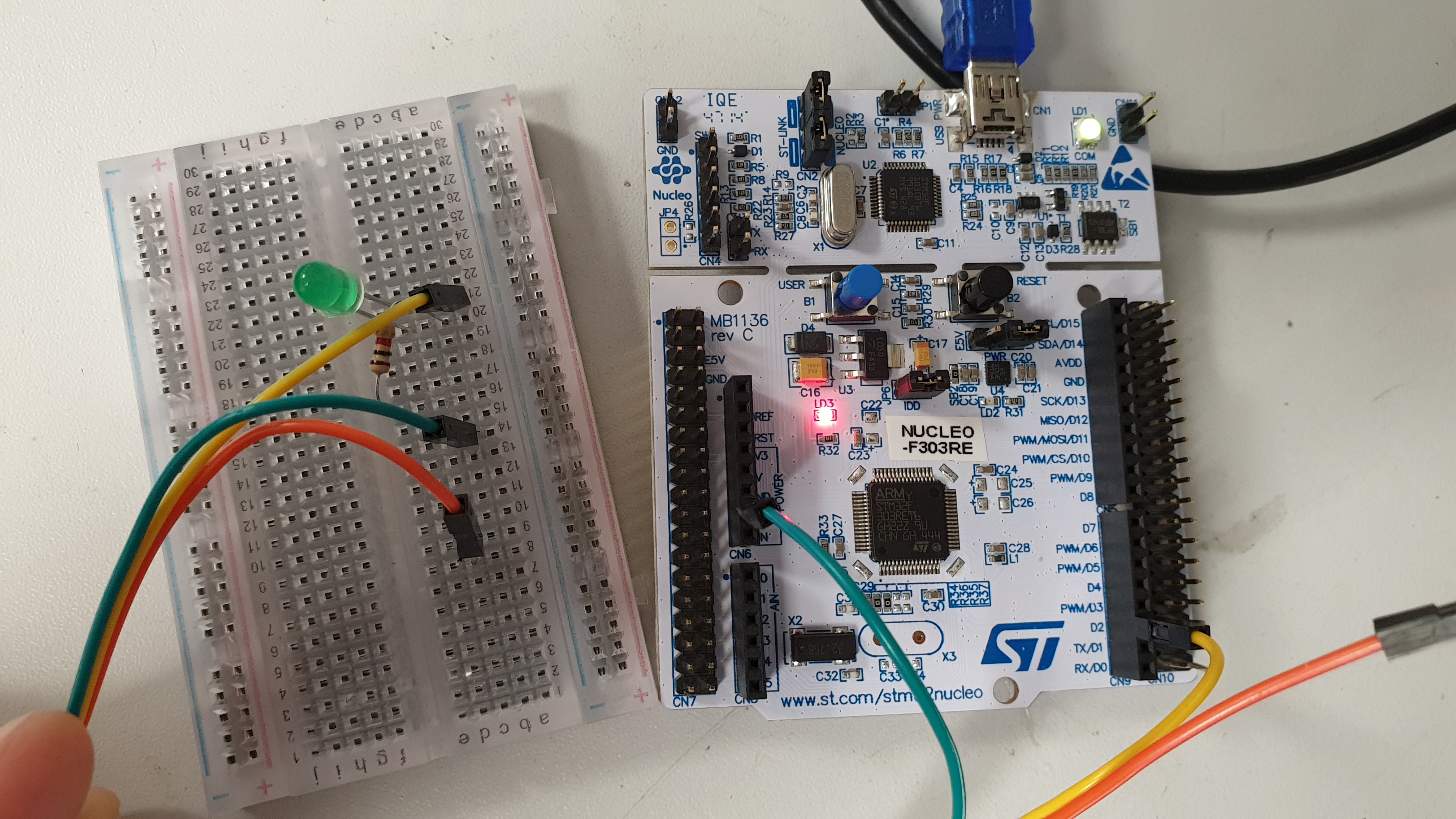
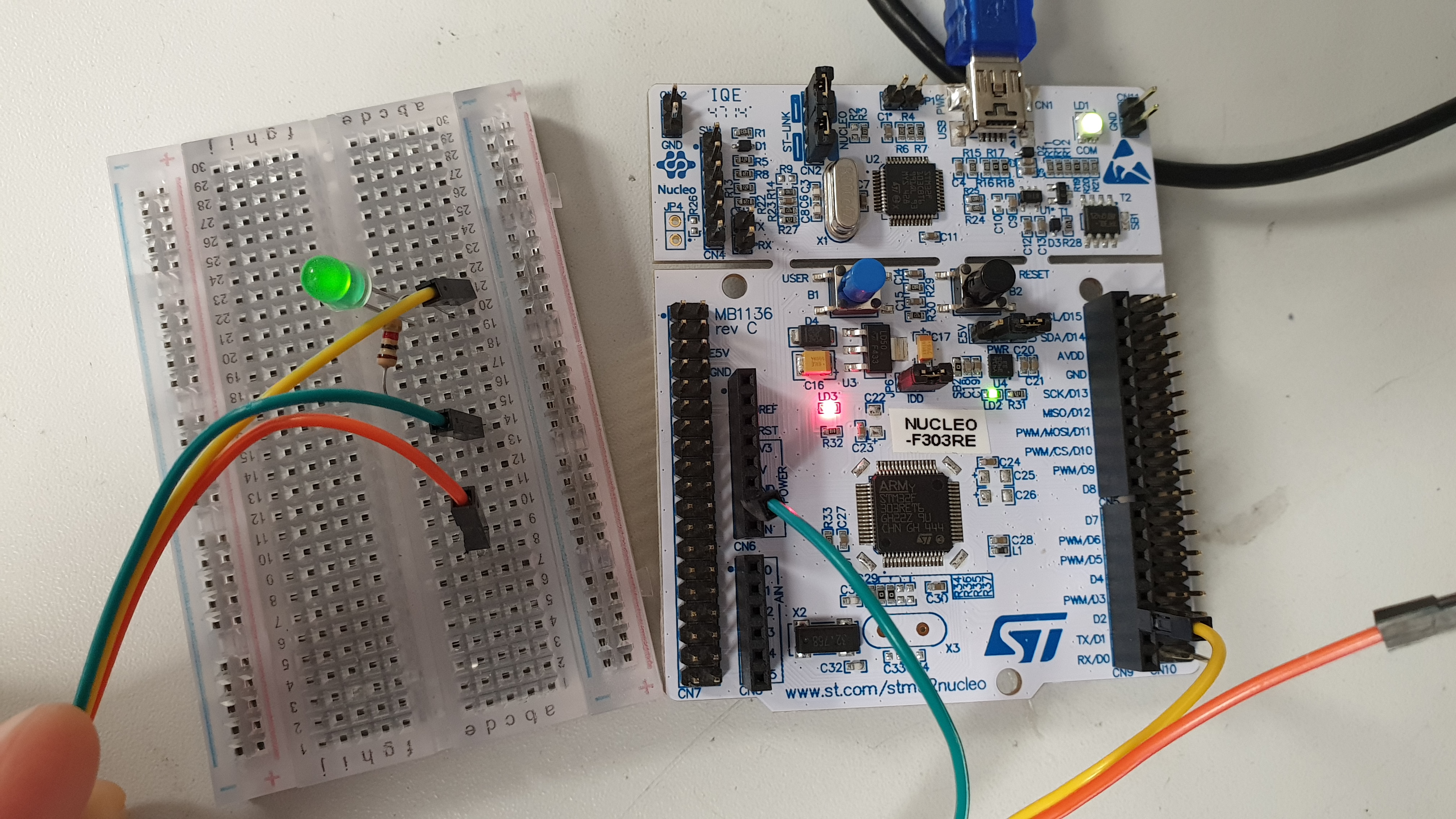
Okay, we are ready to perform adjusting Arduino IDE. I will use STM32 and go trough most important parts of the process. We used breadboard for testing purposes. It was just a diode, resistor and couple wires. Fair enough to do some tricks with the diode. Buckle up and let's go.
The very first step is to add URL that additional boards might be find in board manager. Those URLS are easily found over the web. I attached three links, which we used above.
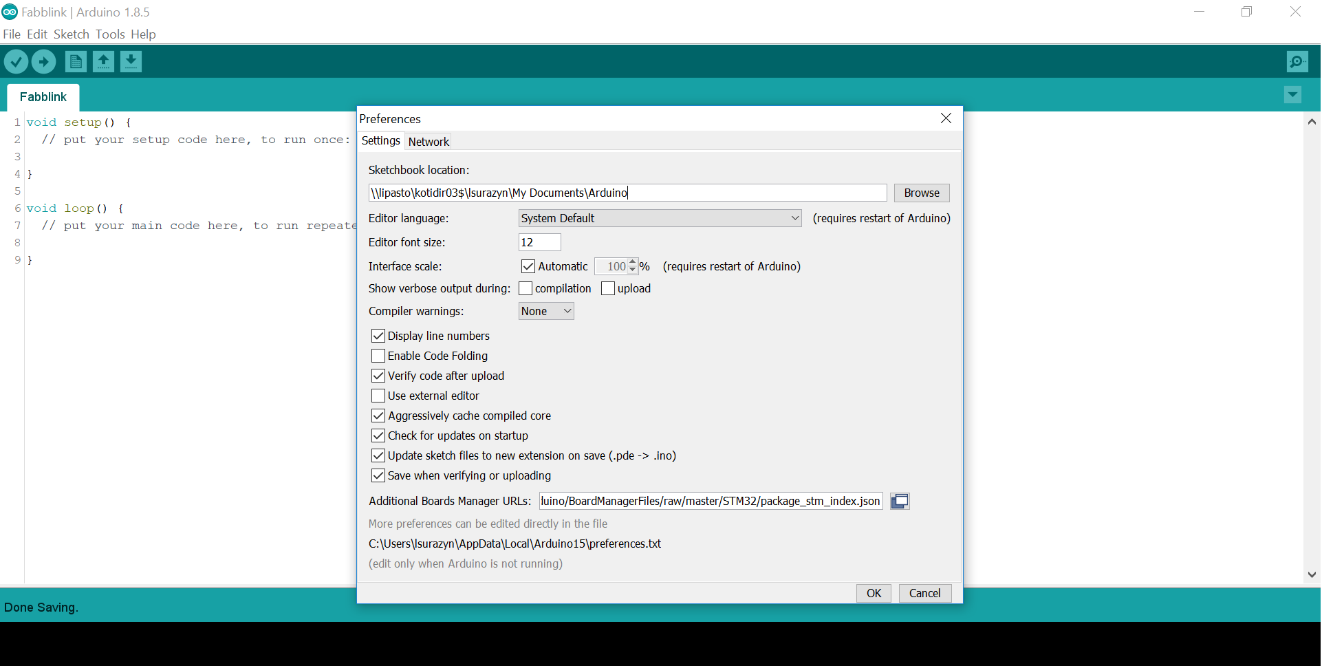
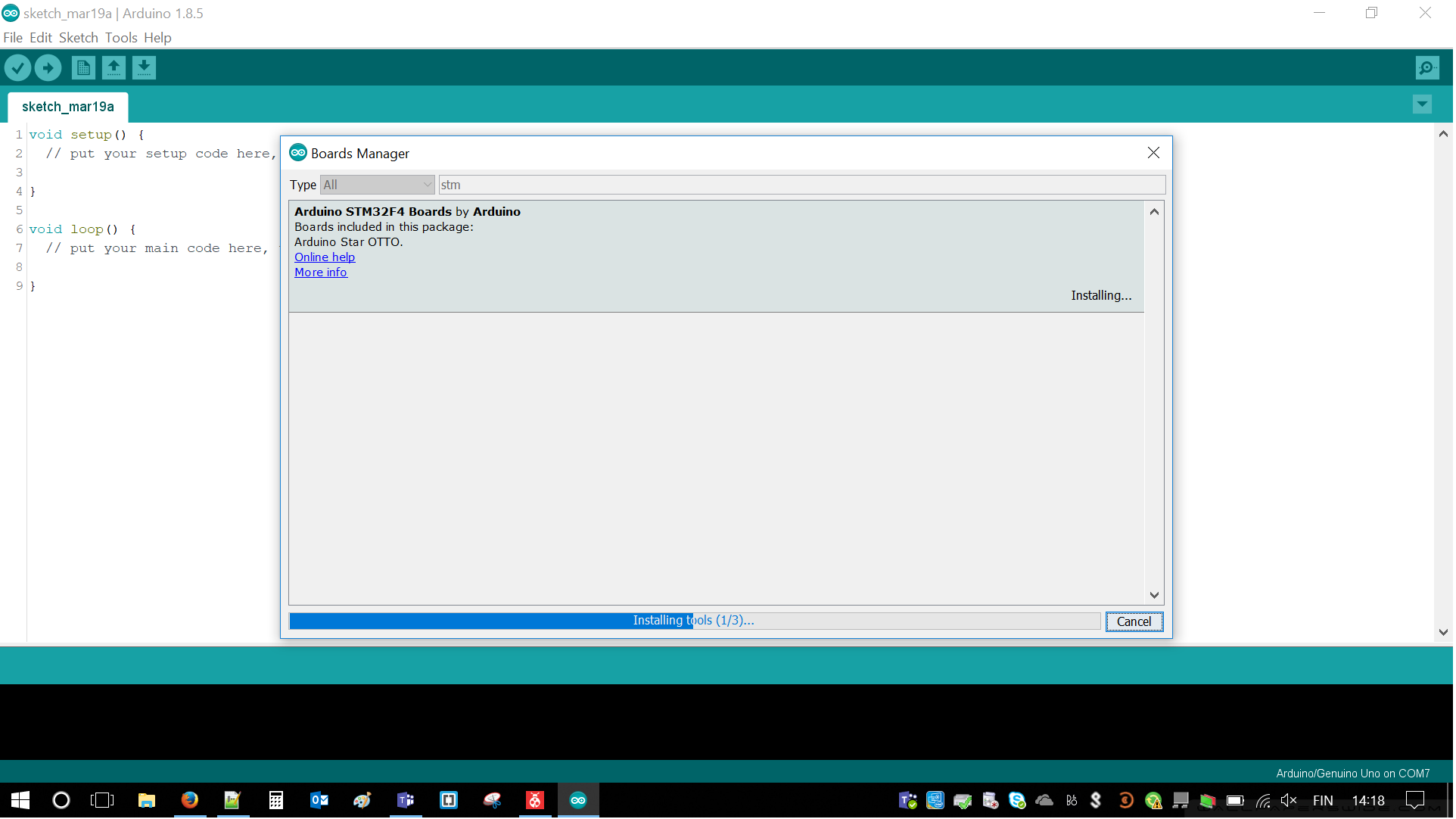
In Tools/Boards Manager Arduino STM Boards may be found. Those has to be installed by clicking one button. In our case it took a while, but when I was doing it at home it took couple seconds. After this step only customization is left.
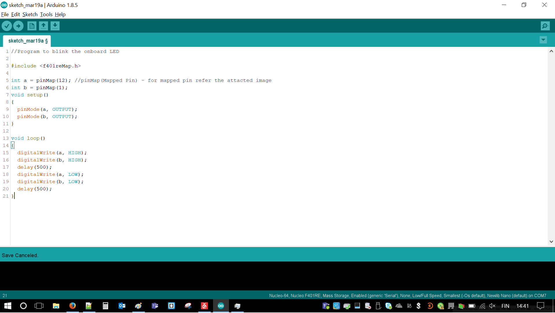
At this point we created project and attached blinking code. Arduino code is very simple and doesn't require much efforts. This is why we liked it and we decided to use it for testing purposes. Still, we have to remember about correct wiring.
Now it is time to customize the board and adjust all the options. There are two important tabs in this case. First of all right Tool/Board has to be chosen. In our case it was Nucleo-64.
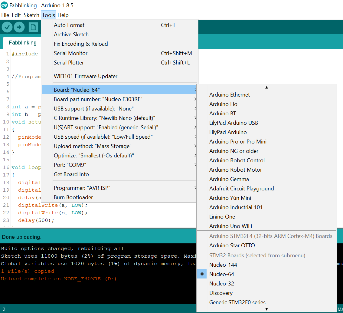
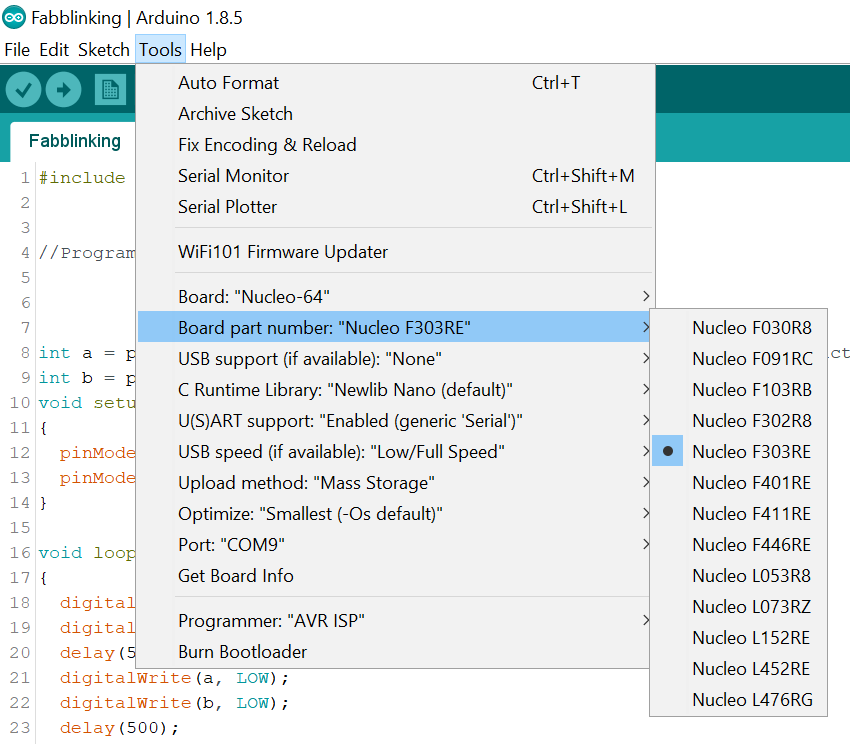
Now, it is time for Tools/Board part number. This can be find on board itself. In our case it was Nucleo F303RE. For the rest of the options may be left as default
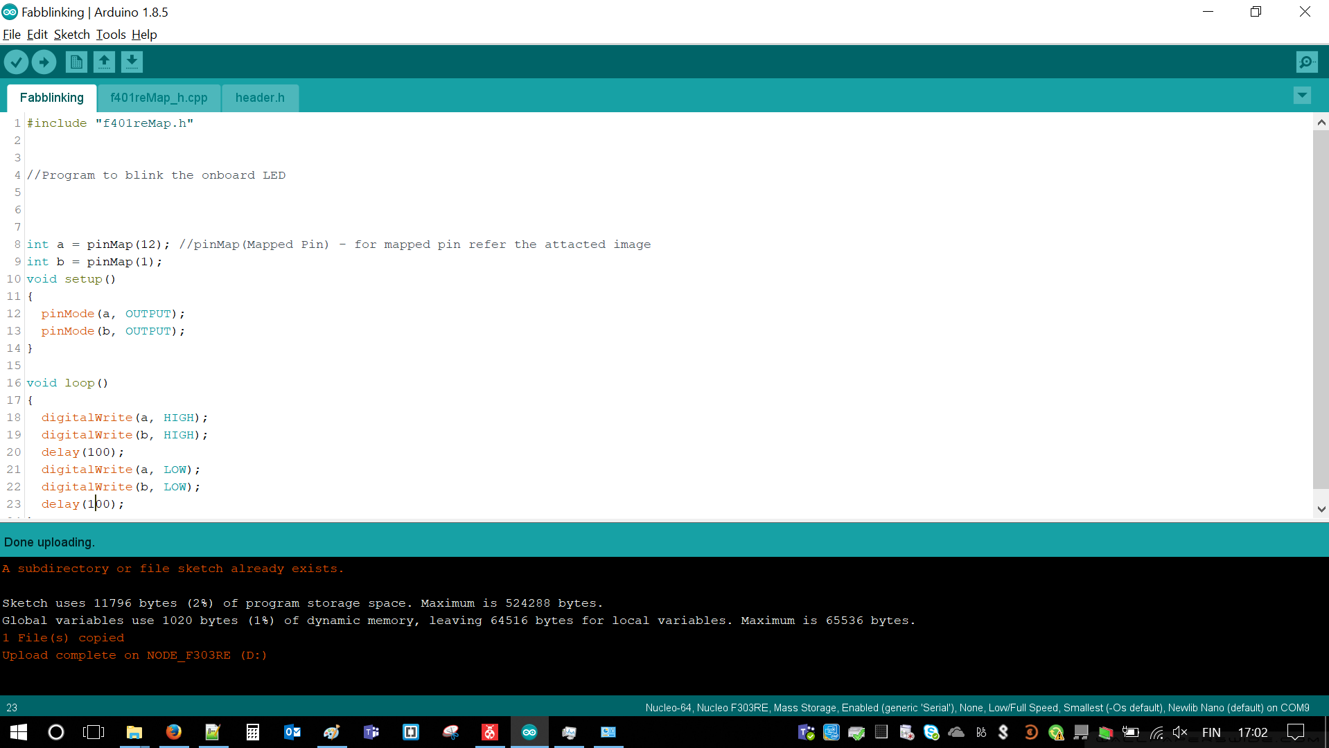
After adjusting everything it was only necessary to compile it and click Upload button to start programming the board
 |
 |
|---|
With very similar steps and using ESP we were able to make some LEDs fading. We just had to taking into account pin numbers, find proper and connect them with LED stripes
 |
 |
|---|
Individual Assignment
ATTiny44A Introduction
I have chosen ATTiny44A and I familiarized with its datasheet from couple reasons. We were using it in previous week and most likely I will use it for my Final project. ATtiny44 is High Performance, Low Power, 8-bit Microcontroler. It can be characterized by:
- Advanced RISC architecture with 120 instructions in one clock cycle
- 32x8 General Purpose Working Registers
- 12 programmable Input/Output Lines (8 bit + 4 bit data)
- Operating Voltage 1.8 to 5.5V
- In-System Programming via SPI Port
- 10-bit ADC
- Low Power Consumption (210 micro Amps @ 1.8V and 1MHz)
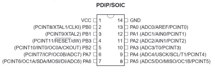
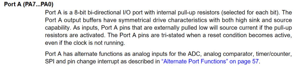
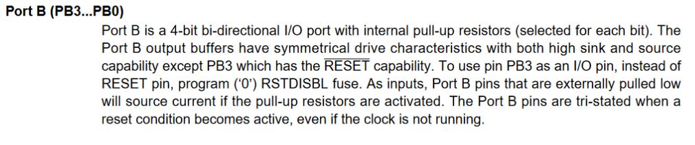
In order to understand what kind of things may be connected to the microcontroler some description of ports is necessary. This may be directly found in datasheet. Well, pretty everything might be find there, so really no groundbreaking discovery.
 |
 |
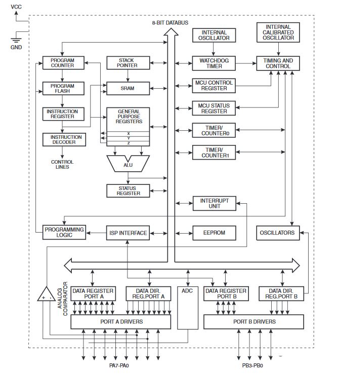
I said that ATTiny44 belongs to RISC architecture. It is true. Below I'm attaching its schematic diagram There are all major parts mentioned. Of course those are just arrays of transistors, resistors and capacitors, which together creates some functionality, e.g. memory, converters or ALU (Arithmetic and Logical Unit) - crucial part.
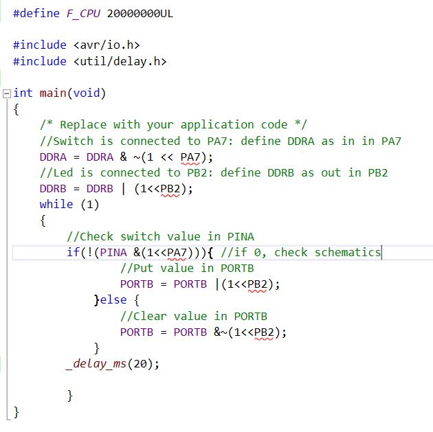
Enough of hardware. It is a time to introduce some C - programming language. First of all, it is crucial to define register status. Those might be either inputs or outputs.
Write to an output pin using: PORTA/PORT |
Read from an input pin: PINA/PINB |
Time for some logical operations. There are quite a lot of them but most important ones are:
- ~ NOT
- & AND
- | OR
- ^ XOR
- << SHIFT LEFT
- >> SHIFT RIGHT
Atmel Studio
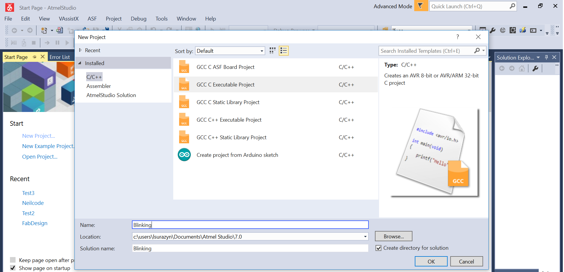
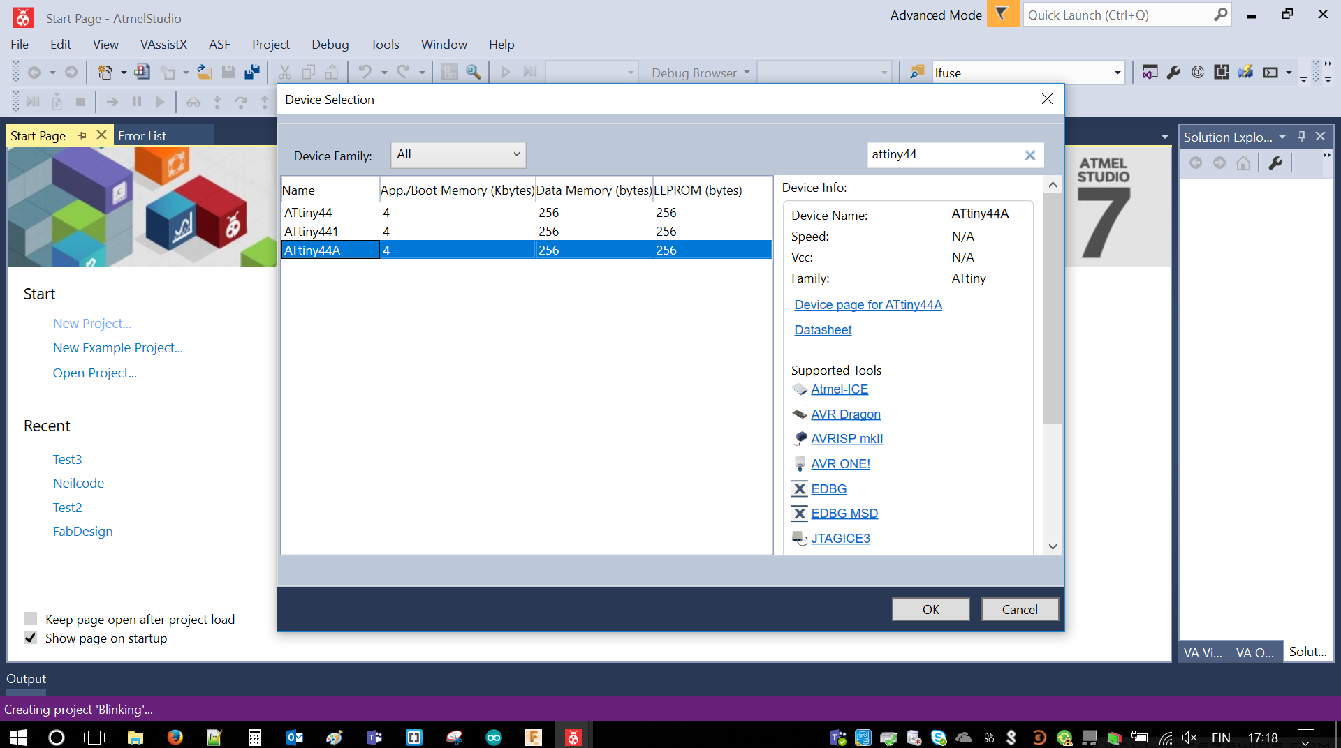
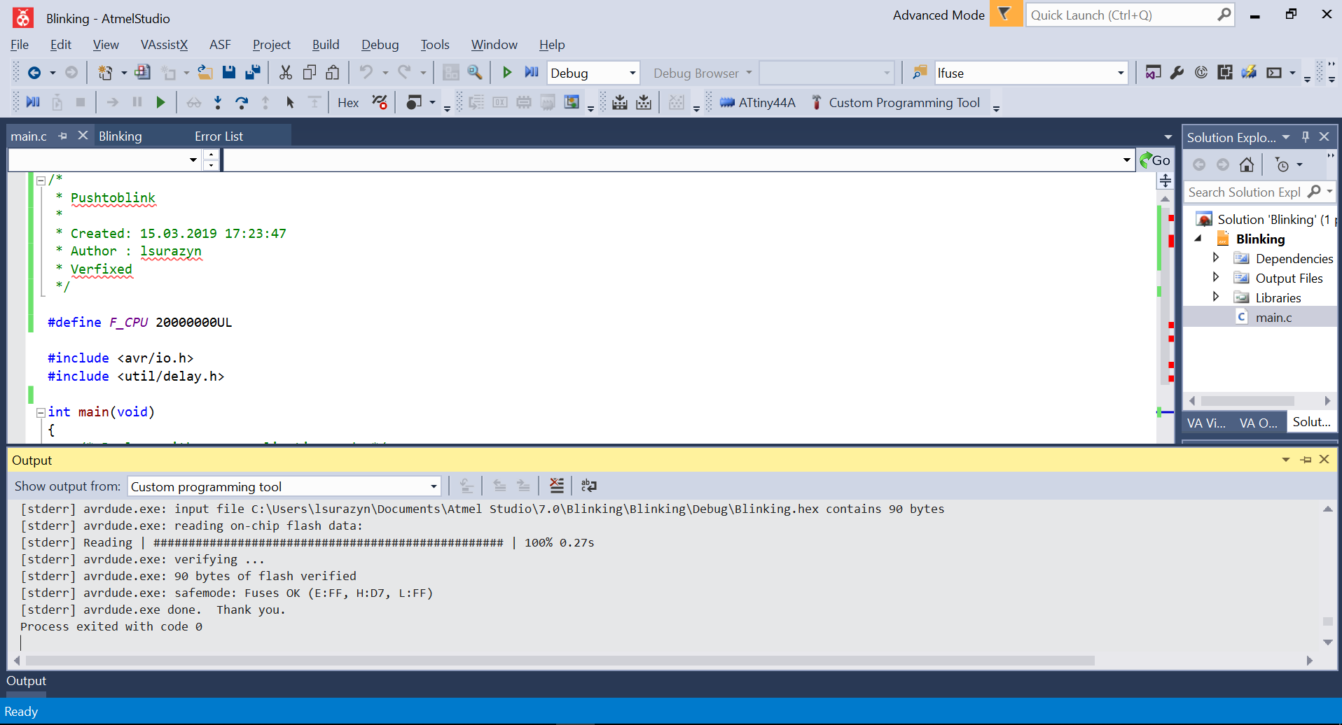
I described how to program my FabBoard with Atmel studio couple weeks ago in Electronics Production. Fortunately, I had everything prepared and working. The only task was to change the code and adjust it that when button will be pushed - LED should turn on. I simply combined previous year student's code. Checked the parameters. Worked perfectly. Below project creation steps with proof of proper compilation.
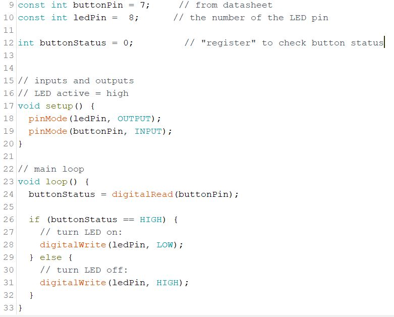
Arduino IDE
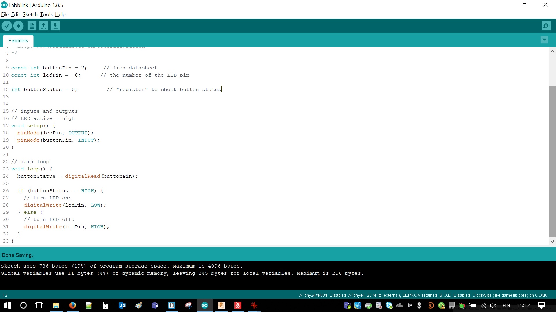
Then it was time for Arduino environment to shine. It is much simpler for the drawback of size and speed of compilation and programming. For instance of Fab Academy projects, the differences are negligible tiny. As tiny as ATTiny.
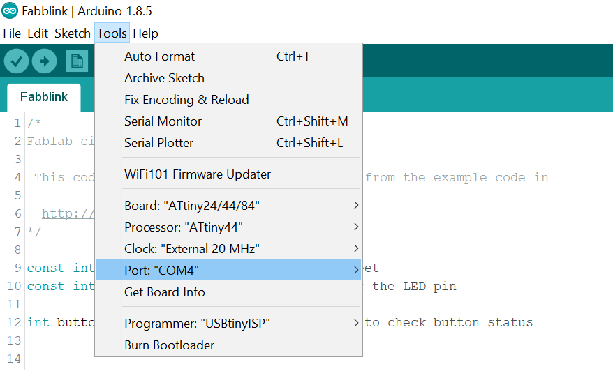
Since I already added different boards during group work I simply used: This web page to add ATTiny44 to programmable boards. Package name is "attiny by David A. Mellis". In my case version was 1.0.2. Most likely previous versions might work with minor differences between them (pinmaps I guess). After that step microcontroller, appeared in board manager. There were couple things to set such as clock and port, which FTDI cable was connected to (just in case of future serial transmissions). Quite easy process. Below a screenshot with correct values.
 |
 |
|---|
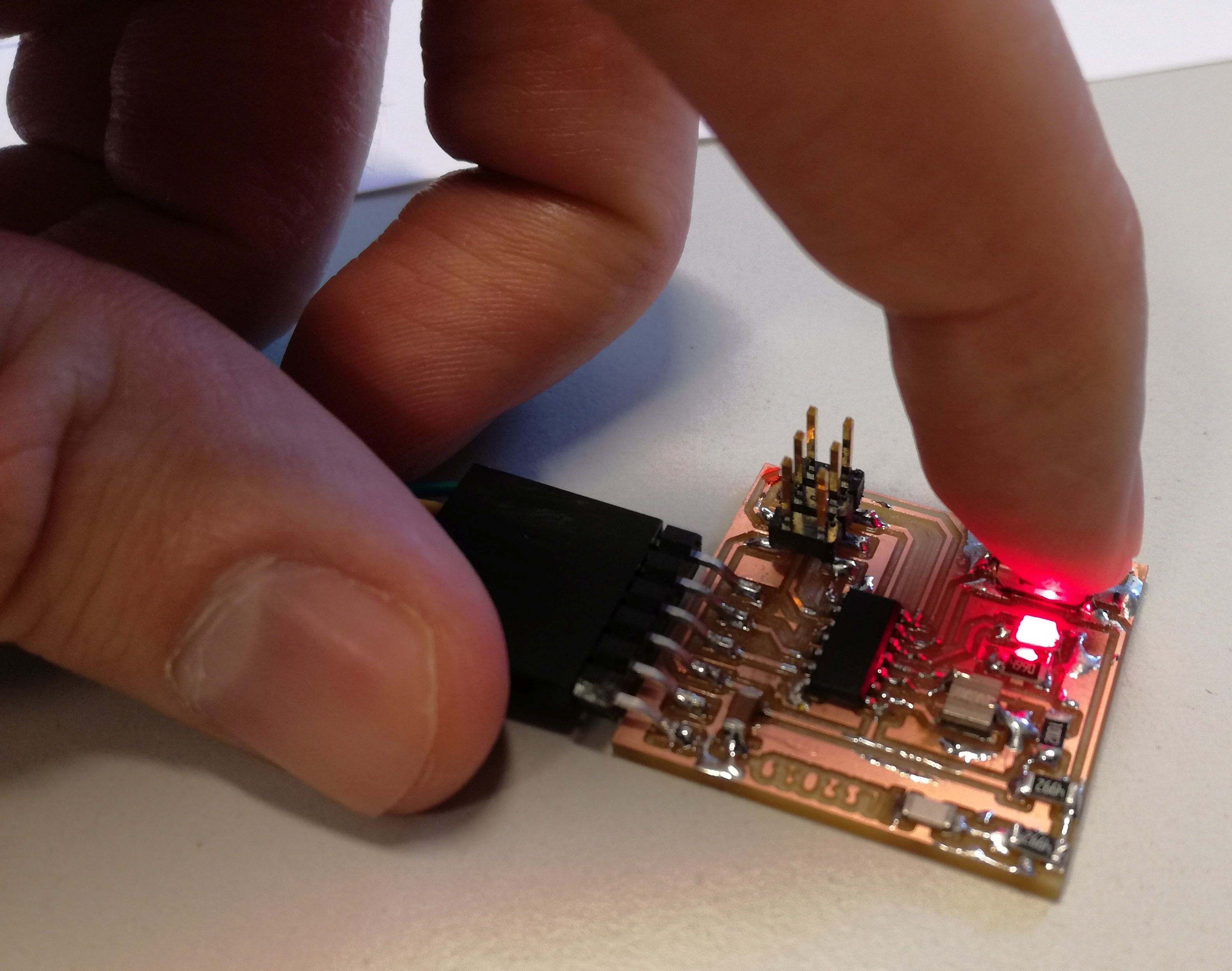
In both cases result was the same. LED was turning on and continue glowing for the duration that button was pushed.
Resources / Credentials
Final thoughts
After all the work during both group and individual assignments couple thoughts arisen in my head. I would like to spend more time on programming with C. However, Arduino IDE was so simple and easy compared to pure C. Amount of libraries and already written code is amazing. It saved time and nerves.
There is also option of Assembler, which we did not concentrate on. It is much better in terms of saving flash and memory of the chip but how much more it is complex than using C/Arduino IDE? I guess I will find out in the future.