Week 12: Output devices
It is very tempting to refer to previous week. I could say that output devices are opposition to input devices. It is very true. I know many input and output devices in Electronics. They are all around. At some point I started to wonder if humans could be considered as input/output devices. This is how I found above image. Unfortunately it is in pounds and not kilograms. Then I have no idea about those numbers. Most likely they are right.
Group work
Members: Gleb, Marjo, Perttu and me
Measure the power consumption of an output device.
Green LED
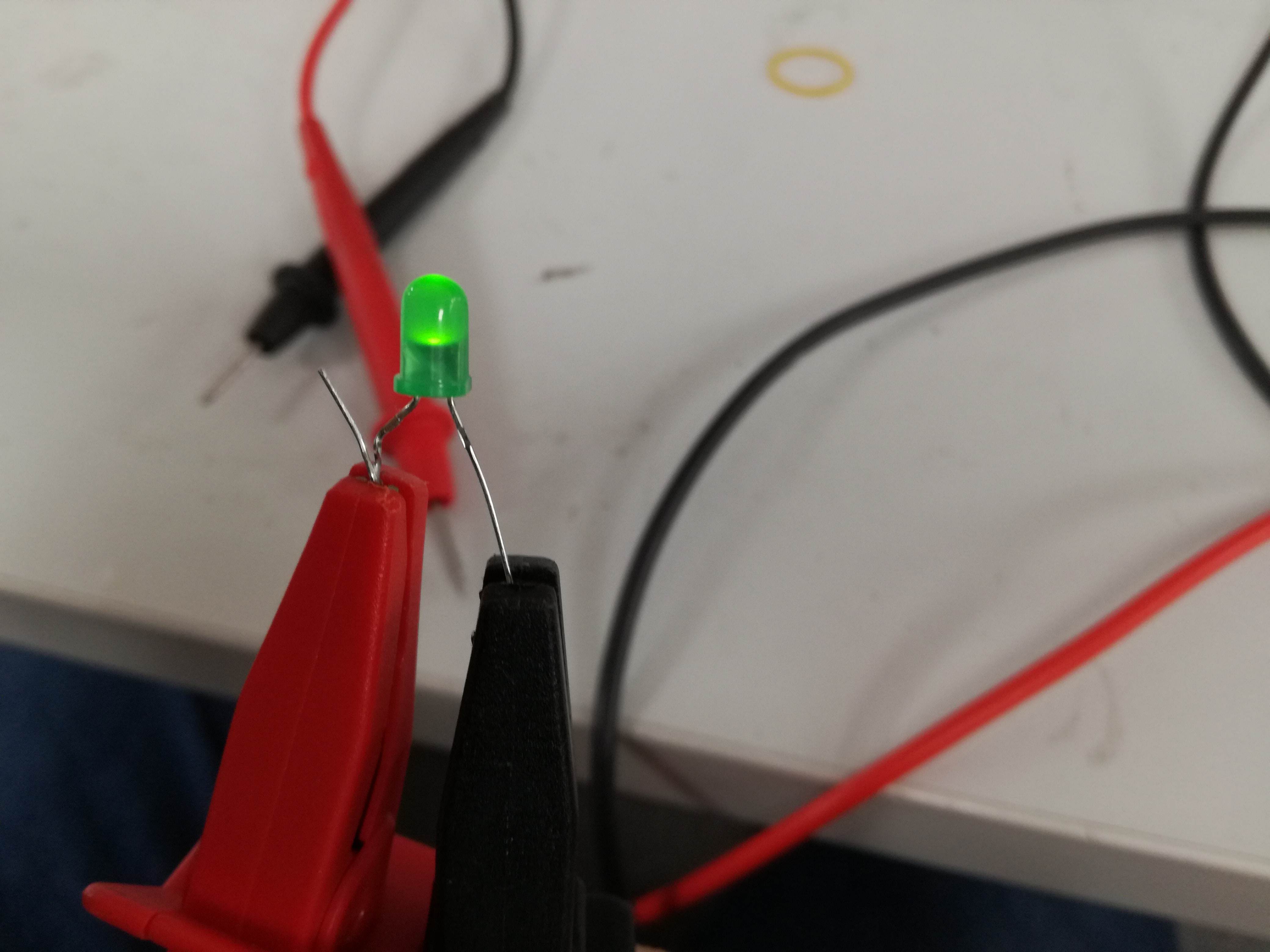
There are no more obvious choice as Light emitting diodes. Results are visible with naked eye and connection is very simple. We have found some random green LED on burned board. Our decision was to measure forward voltage to current characteristics. From this power might be easily calculated as Power = Voltage x Current. This is knowledge taken from ancient scrolls: >>PUIMURI<<
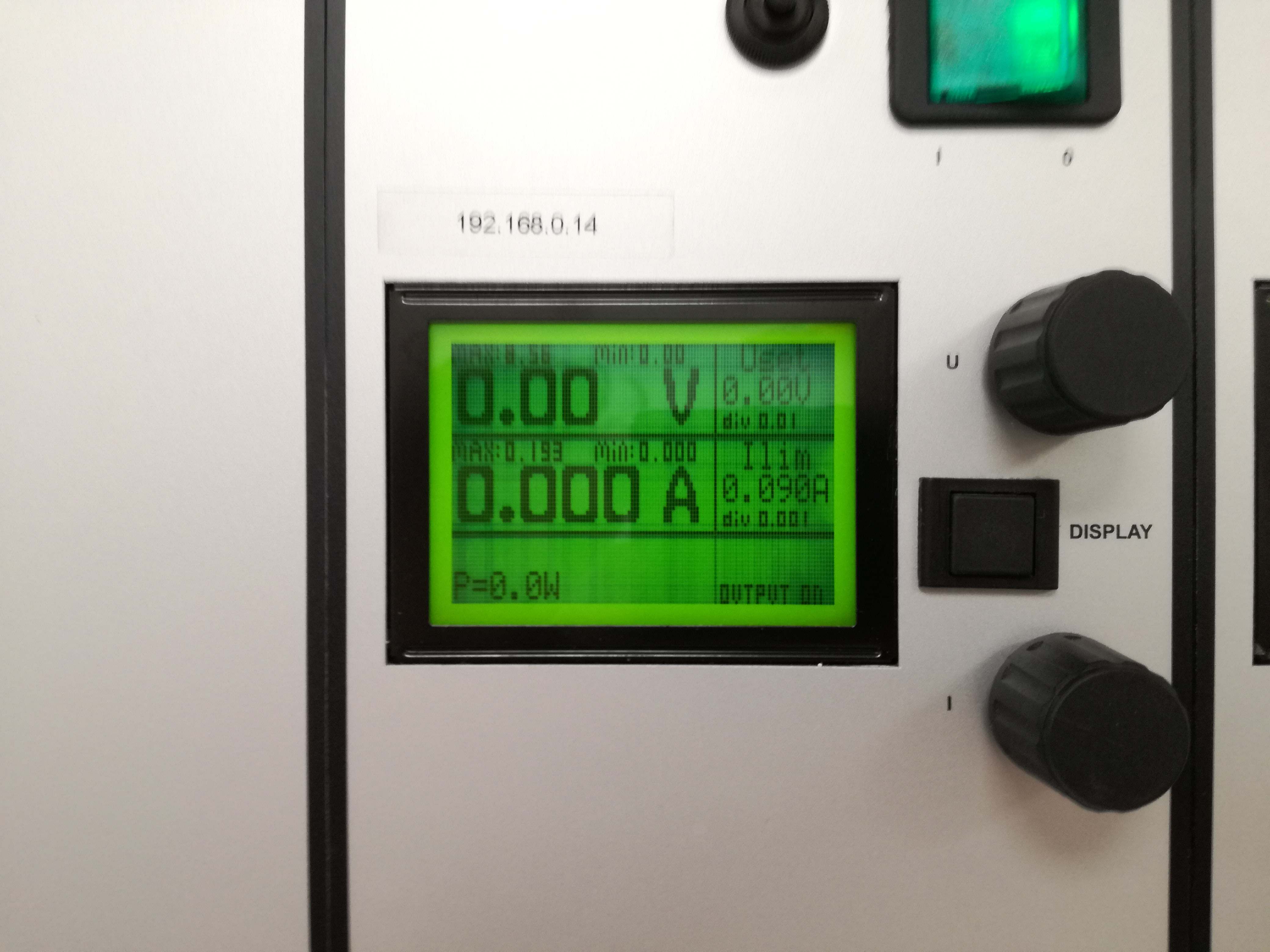
We have connected our LED to the laboratory power supply. It is smart construction as it has both current and voltage limited output. Meaning it would be really difficult to burn our LED but of course we manged.
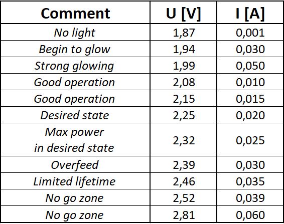
We were feeding LED with voltage, where our current was limited every time. We managed to obtain full characteristics from barely glowing to final breath of our LED. Results are shown below.
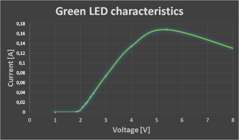
In so called "meantime" we managed to write down our observations during measuring process. We have recognized voltage, where LED started to glow and finally burned it. From basic knowledge, we knew that LEDs are feeling best around 20 mA. Rising the current resulted in stronger glow but also limited lifetime of our diode. Obtained curve was similar to ones, which may be found in datasheets. Observations below:
Motherboard Fan
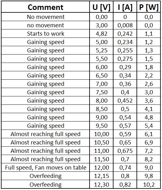
Our next choice was cooling fan. This particular piece was doing its best to cool down some electrical circuit. Nominal values were 12 Volts at 0.9 Ampere. Those can be read from the fan itself. It is also proving that we are able to read despite having only Master Degrees. In this measurement we have shown some mercy and did not destroy measured element. The main reason was usability of such fan as Summer is coming.
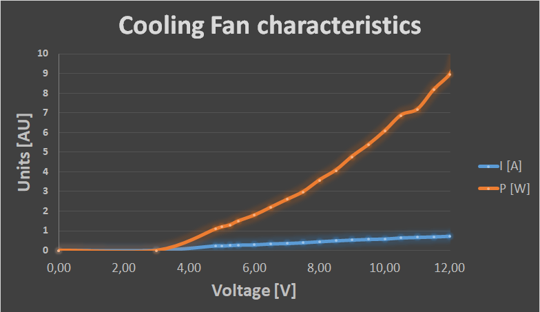
Once again we used our laboratory power supply. This time we limited current to maximum value of 0.9 Amp and played with voltage. We managed to obtain both Current vs Voltage and Power vs Voltage characteristics.
Once again we wrote down our observations during measuring process. We observed that at some very low voltage it was necessary to manually start the fan and it keeps spinning (slow and with issues). Before it starts it is trying to compensate lack of voltage with current. It is unfortunately not enough. Table with our results and observations below:
Individual work
Time to do something related to final project again. I will have both input and output devices on TARS. Prototyping is important as experience tells me that first versions are always not fully functional. In this week I decided to go for something more challenging that ATTiny44A. I used ATMega328p-AU in TQFP package. It has 44 pins and is much more difficult to solder and handle.
The main reason to use bigger microcontroler are more outputs and more memory. I'm planning to use LCD screen as interface. There are also couple sensors, and buttons. Probably if I would be AVR God I would be able to use ATTiny for this purposes but I don't really feel to complicate my life even more.
There are couple things, which were designed and create this week. In general I forced ATMega to visualize some text lines on 2x16 LCD screen. I will go trough the process step by step.
PCB design
This was most likely the longest part, which required the most thinking. I found ATMega328p footprint in FabAcademy library. I read datasheet, which may be found on this website. From the datasheet I learned pin configurations. It was enough to design circuit with following features:
- ISP
- 16x2 LCD display
- 2 sensor Inputs (Photoresistor and Thermistor)
- 2 button Inputs
- 2 MOS controllable outputs
- test LED (useful with troubleshooting)
- Serial port via FTDI connection
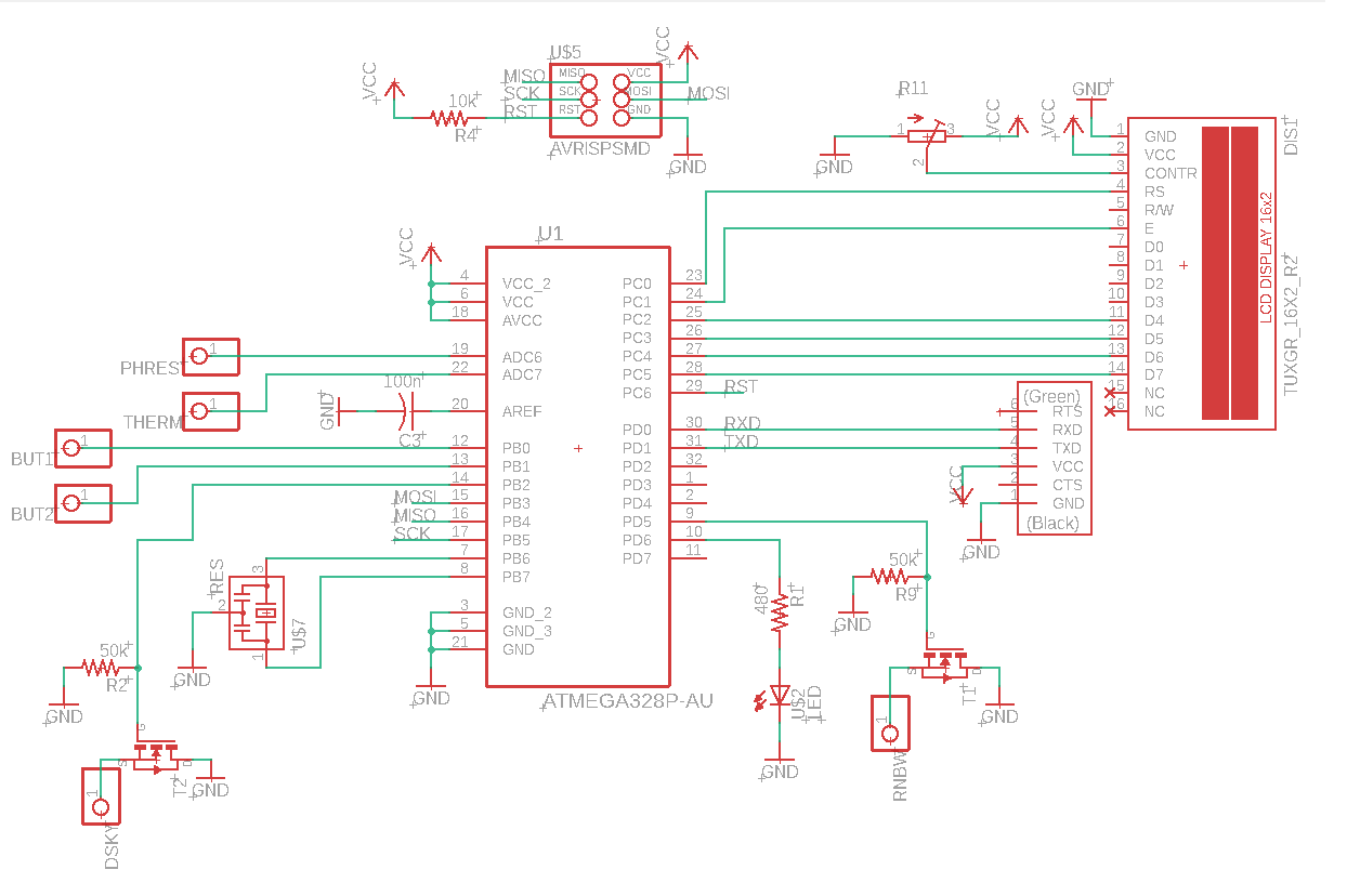
I will explain those features more precisely in Final project parts. For this week the most important is LCD screen, which is obviously an output device. It might be found in display-lcd library. Such displays might work in two modes: 4bit or 8bit. The main reason is amount of connections, but also speed (irrelevant for me) and way of programming them. I followed the only right way - 4 bit mode. It requires 6 connections for data and 3 connections for powering up. In my case I used PORTC of my ATMega328p but any other port would work. It was my own comfort. As I planned PCB on the paper first.
I learned connections and details regarding LCD screen from this website. There is also explanation how to connect the pins and example code given. My schematic in the end looked:
After an hour of thinking of possible issues and fixing mistakes I moved to design of PCB. I decided my board will have size of 7 x 5 [cm]. I could easily make it much smaller but this will fit TARS chassis. I left some space for screws and glue if needed. I spread the Inputs/Outputs in comfortable way. There is also trimmer responsible for LCD contrast on the board.
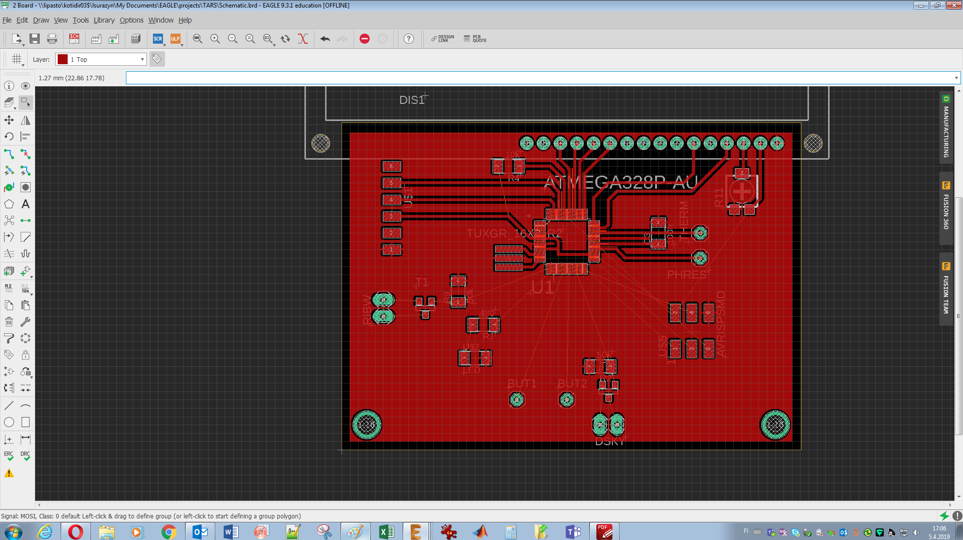
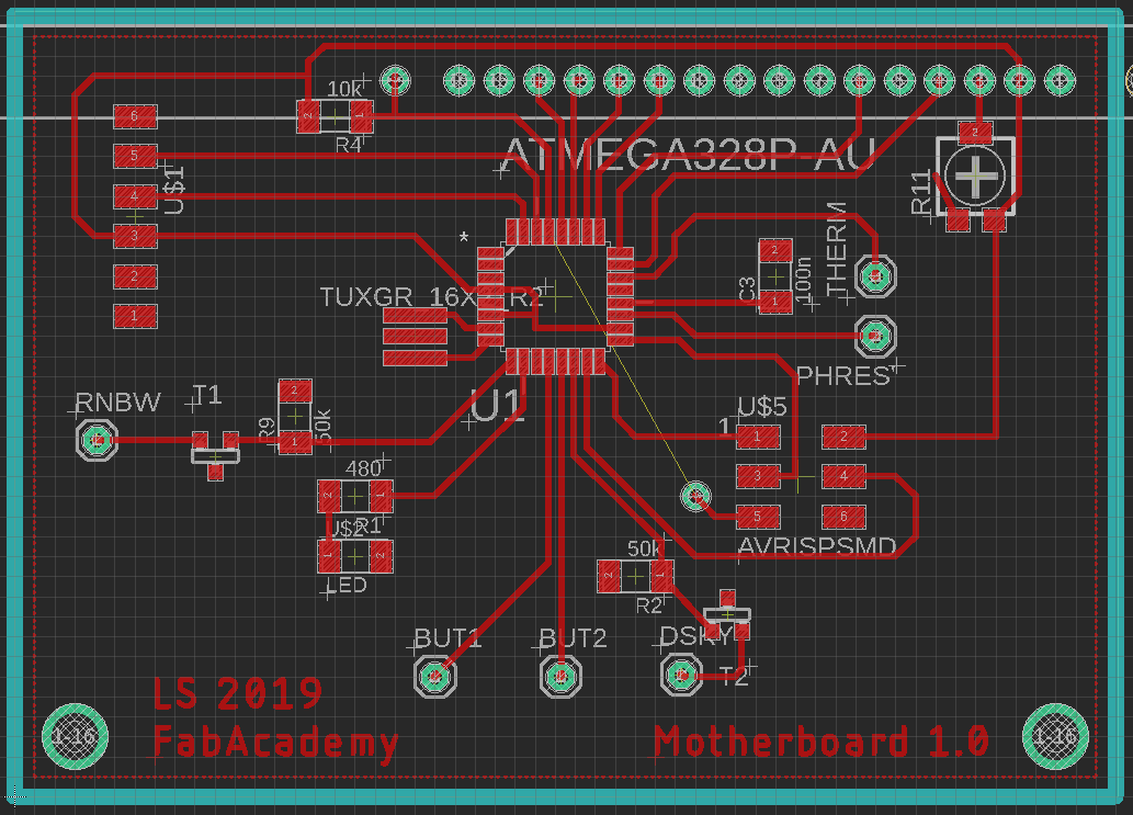
I intentionally left one trace unrouted. It is reset signal for ISP. I couldn't route it around PCB in easy way, even using bridges with 0 Ohm resistors. Since this is a prototype board a wire will connect it. Hopefully I will work it out in next version. Time will show.
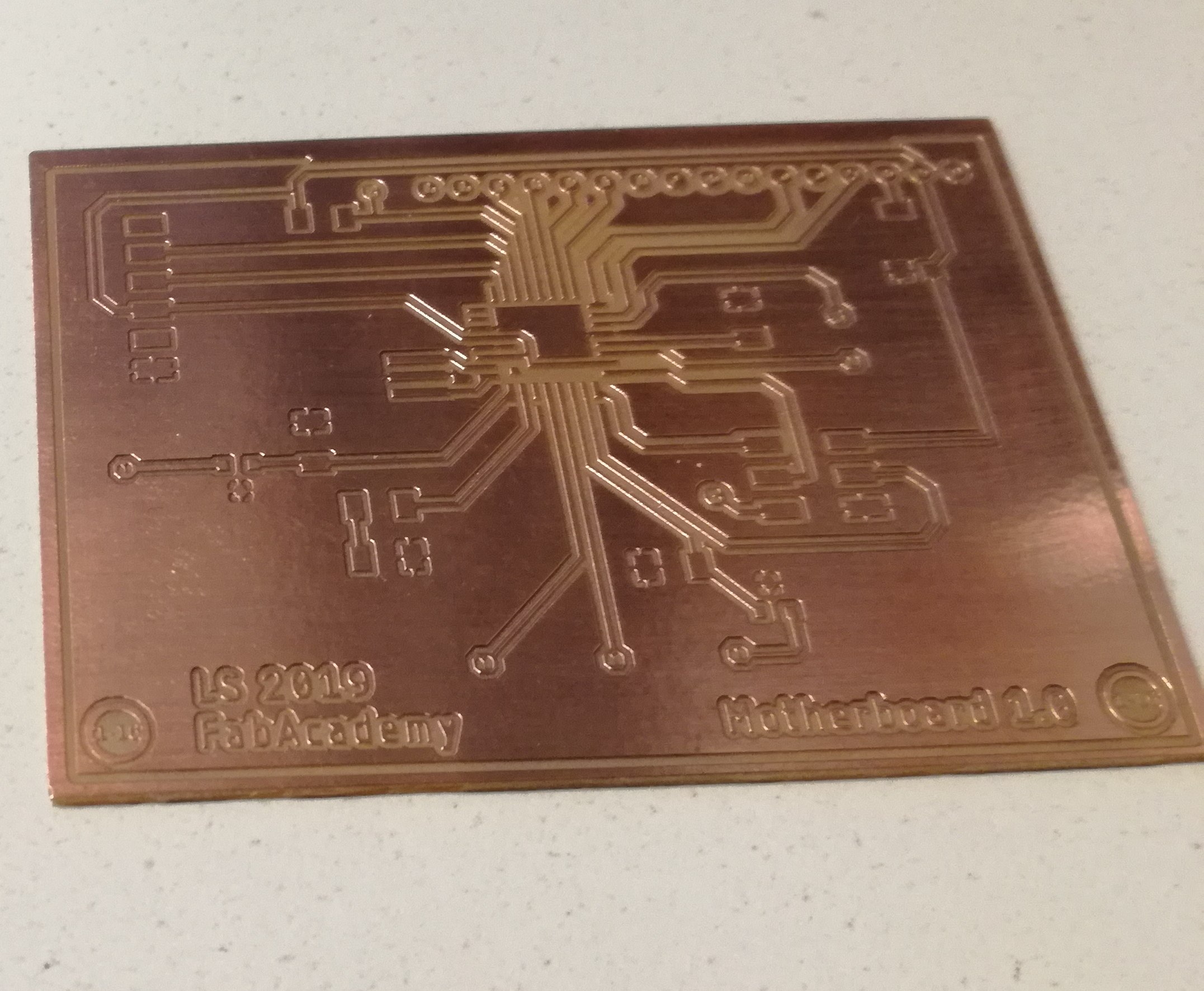
Milling the board was trivial. I already done it several times. Once again knowledge from Electronics production was required. I used standard tools: 1mm milling bit for outline and 02-05 mm milling bit for traces. Everything was clear and easy.
Soldering
Compared to previous part, soldering took just a moment. I used an old trick in order to solder microcontroller. I placed it and aligned perfectly. Then i put a lot of flux around and soldered every line creating big shorts. Then I removed them using copper braid.
As always I didn't take any photos in the middle of the process. I'm focused on choosing right parts but I took a photo of nicely milled boards.
Programming and testing
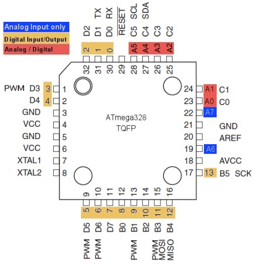
For programming purposes I used Arduino IDE. It required adding my ATMega to the boards. Tutorial how to make it might be found on: this website. Then I needed a pinmap. Fortunately, it just require a bit of goggling, map looks exactly like that:
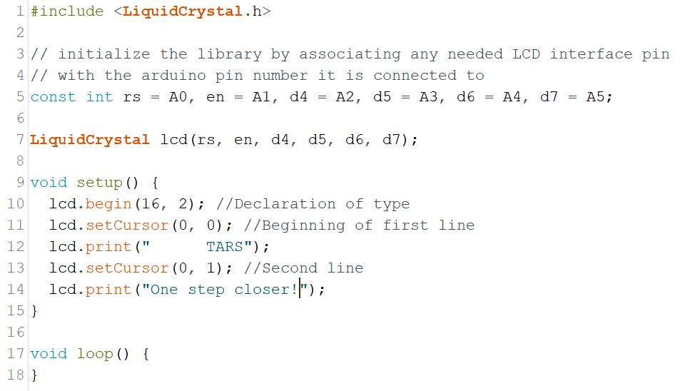
Code is very simple. It is required to include LiquidCrystal.h library. Then six pins has to be define. There are four data pins (d4 - d7 in my code), reset (rs) and enable (en). I decided to define them before LiquidCrystal function. Writing something with LCD screen starts with lcd.begin, where values typical for each LCD screen are set. In my case there were 16 digits in two rows but there are bigger and smaller screens. Then with lcd.SetCursor place, where writing will start is defined. In my case I was always setting it to beginning of the line (0,0) or (0,1). Printing itself is done using lcd.print, where text can be put. It might be also a value of the sensor or hexadecimal number.
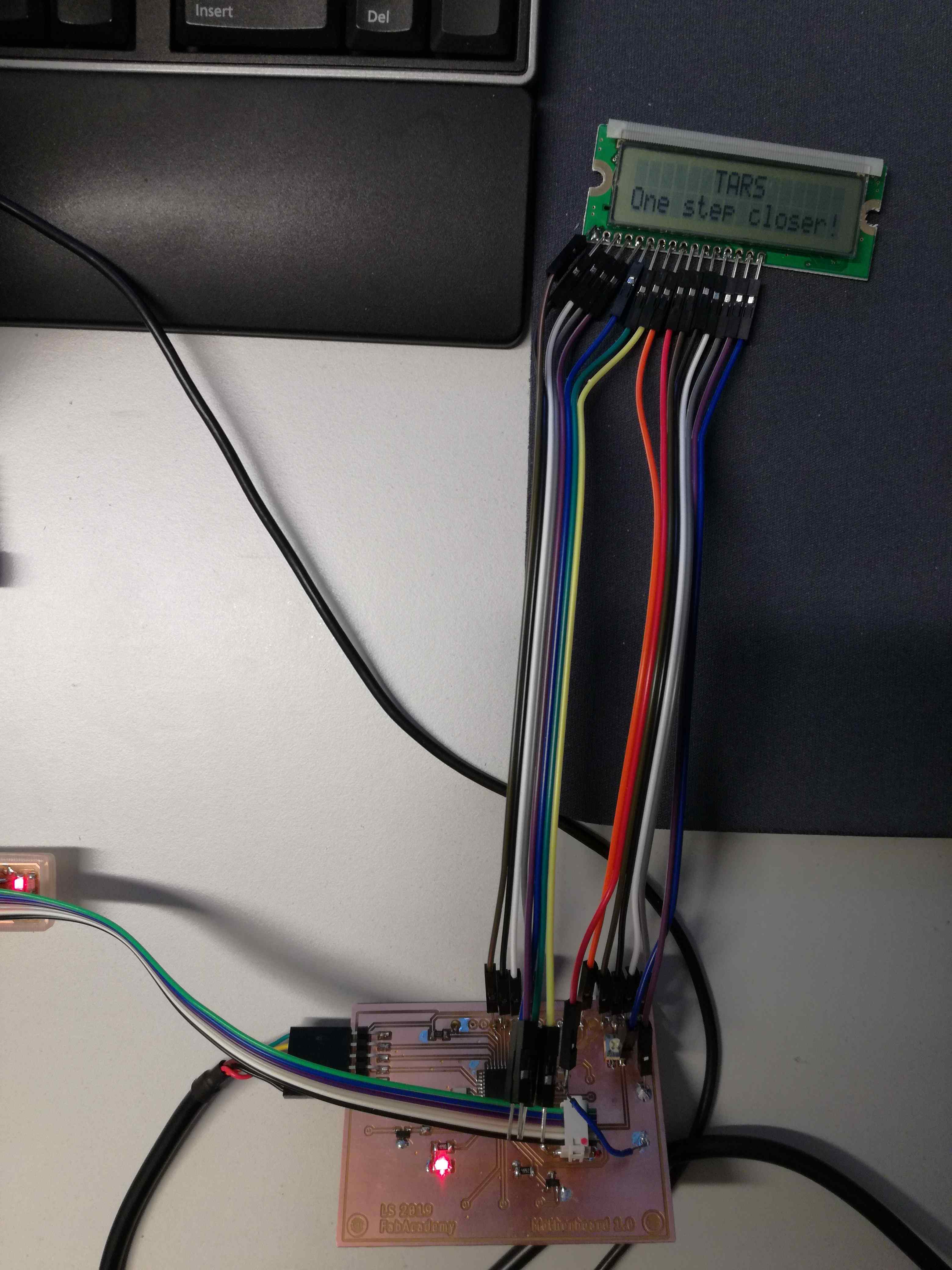
With map and correct board in board manager I was able to blink my test LED. I was really happy that I added it. Simplest way to make sanity check. My board was ready. I soldered wires to the LCD screen and corresponding pins on my board. In future I think I will use SMD pinheads, this will be more elegant and efficient way. After powering everything up LCD screen lighted up. That was a good sign.
However, after programming screen remained unchanged. After several minutes of checking the connections I realized that R/W pin is "hanging", where it should be grounded (only write mode). After fixing this issue my screen woke up and started to work!
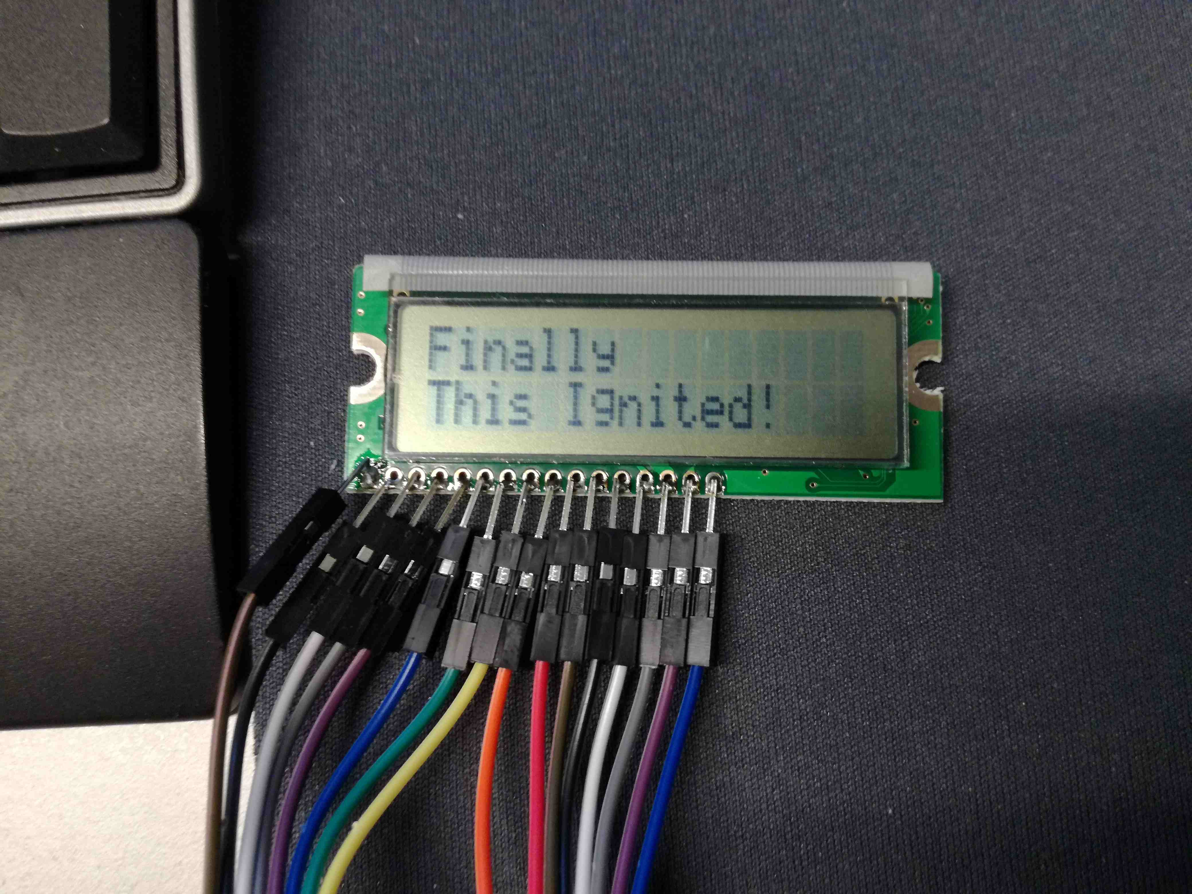
Final result
From now on I could print any sentences, which are shorter than 16 signs. Right now there are numerous ways I could make use of it. Print values of sensors. Interact with user. Annoy someone.
Troubleshooting
There was one accident that happened during the process. It stole a bit of my life. I bricked my AVR. Not intentionally, obviously. During burning bootloader I set something incorrectly and rewrote fuses. Unfortunately, those were changed in a way that ATMega got "bricked". It didn't respond on anything, Avrdude was simply telling me that all fuses are blank (a lot of FFFFFFFFFFF). As I was really not eager to re-solder everything I was goggling for as long as needed. I reprogrammed clock fuses in a way that it required 5V Peak-to-peak voltage with 1 MHz frequency (clock was still divided by 8). It was solved by combining:
In general this code needs to be executed after providing proper clock signal (from signal generator in my case):
avrdude -p m328p -c usbtiny -e -U lfuse:w:0xe2:m -U hfuse:w:0xd9:m
avrdude -p m328p -c usbtiny -e -U lfuse:w:0xff:m -U hfuse:w:0xd9:m
Conclusions
There is couple things, which might be repaired or improved. First of all there is lack of ground for R/W pin. I have to fix connections between LCD screen and Motherboard. I could make the board a bit smaller and provide power for peripheral circuits (based on MOS transistors) or add powering points. I should fix this Reset line, couple vias are unnecessary. I should keep as low amount of drills as possible. Maybe add one more coupling capacitor. Amen.
Files:
Download: LCDDownload: Eagle schematic Download: Eagle board