Week 8: Computer-controlled machining
Make it big! A credo for this week assignment. Things are starting to be serious. I was just wondering if all my previous work was small? Well, electronics was pretty small but I didn't have complexes. I goggled the credo and surprisingly first result is : Make it Big from Wham!. Please don't make me do it to the sound of "Careless whisper". Neither, I would like to make it to "Wake Me Up Before You Go-Go". Alright, this time machine is big so let's adjust the music to the machine: Rage against the machine!
Group Assignment
Team: every single student of FA2019
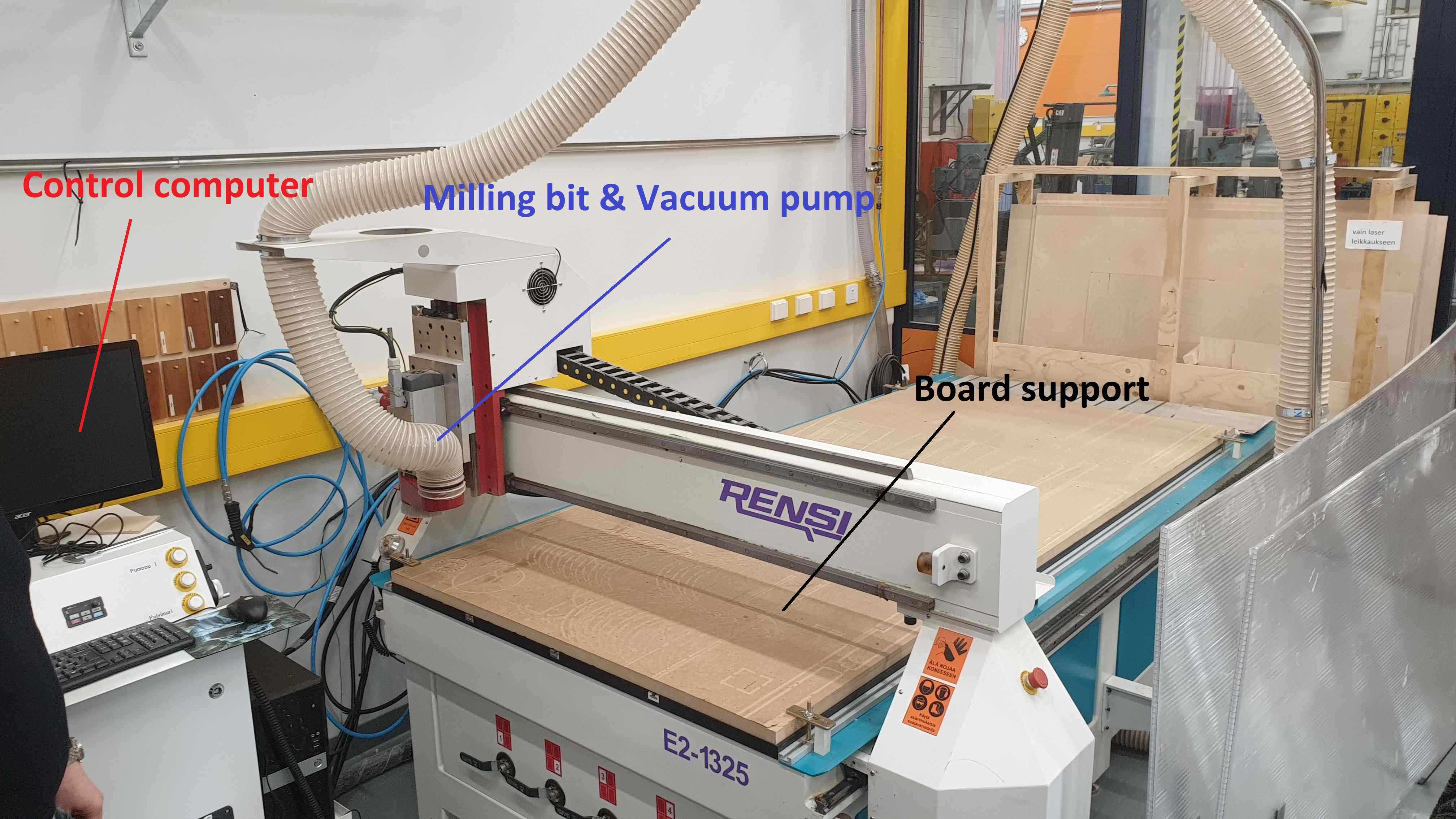
There were couple things on the menu, we should familiarize with speeds, feeds, toolpath and test run-out on our machine, which for this week was Rensi E2-1325.
Our work started with some theory about CNC milling, limitations and advantages of our machine and material. Next part was safety instructions, as this time things are starting to be serious. We would like to omit situations such as cut fingers, fire, flying drills. Safety glasses are obvious choice, when CNC milling machine is working. Hearing protection is beneficial. In general we decided to use Fusion 360 for our designs, so far this software proven to be very flexible. Just a side note and "holla!" for the Autodesk, I will send my bank account number later.
In general, topics in chronological order were:
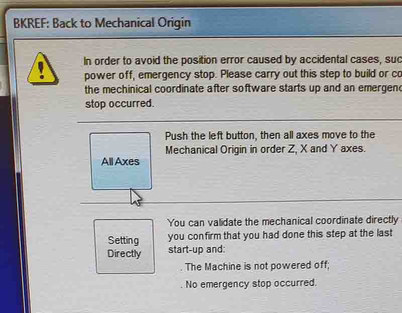
- Starting(Powering up) - checking machine status and preparing to work
- Software - dedicated software, which is using .NC files
- Setting feeds and speeds
- Moving spindle (X,Y,Z) - moving around milling bit in safe and accurate way
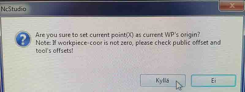
- Resetting(zeroing) axels - setting (X,Y,Z) points of our design on the substrate
- Changing tool - using different milling bits
- Running simulation -
- Begin milling
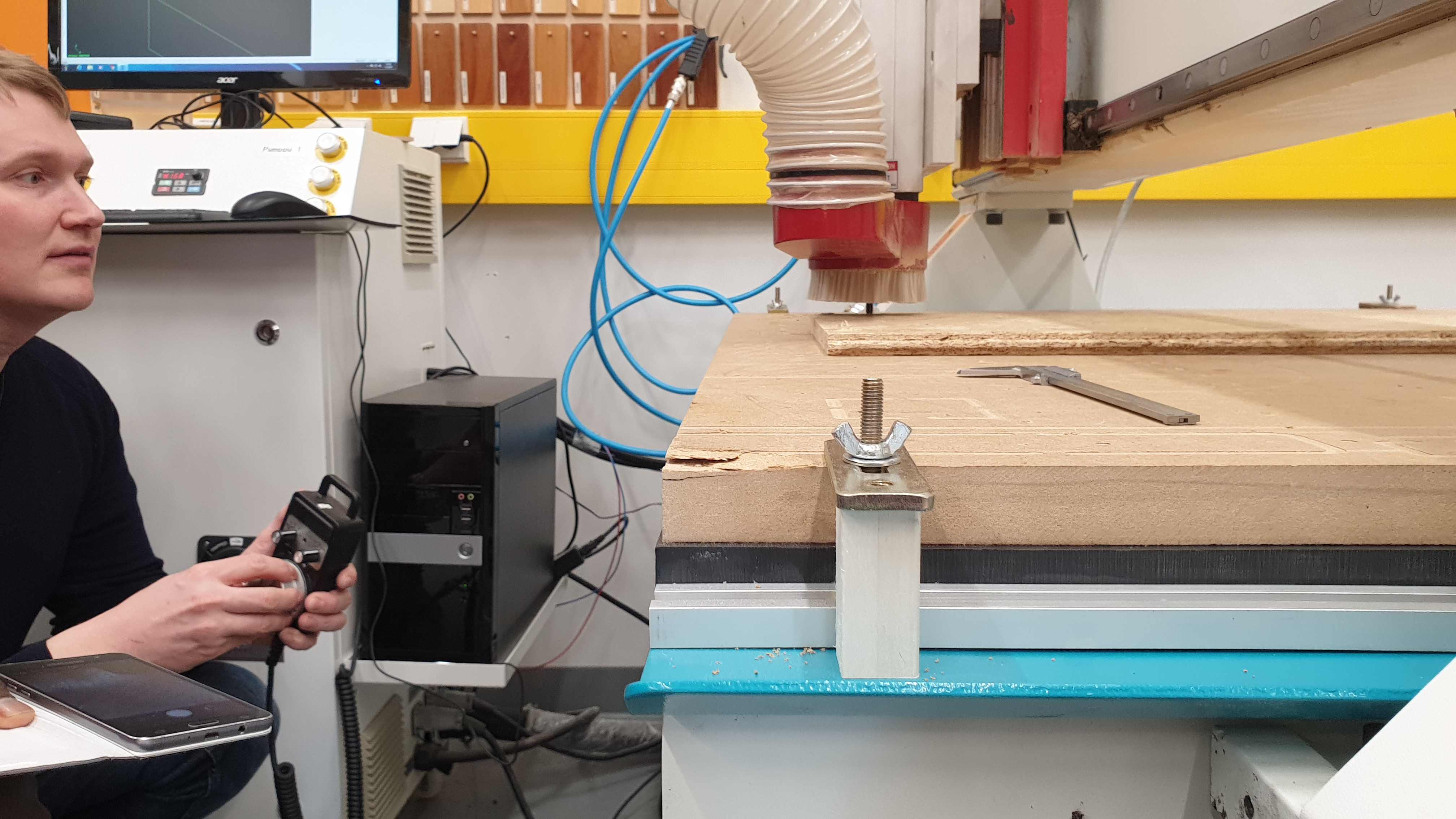
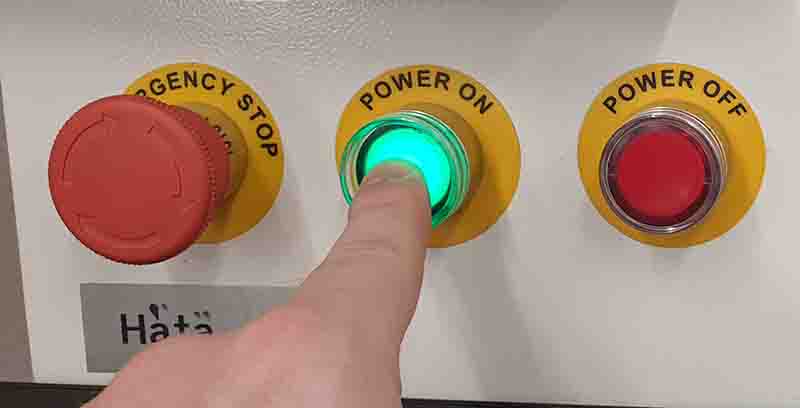
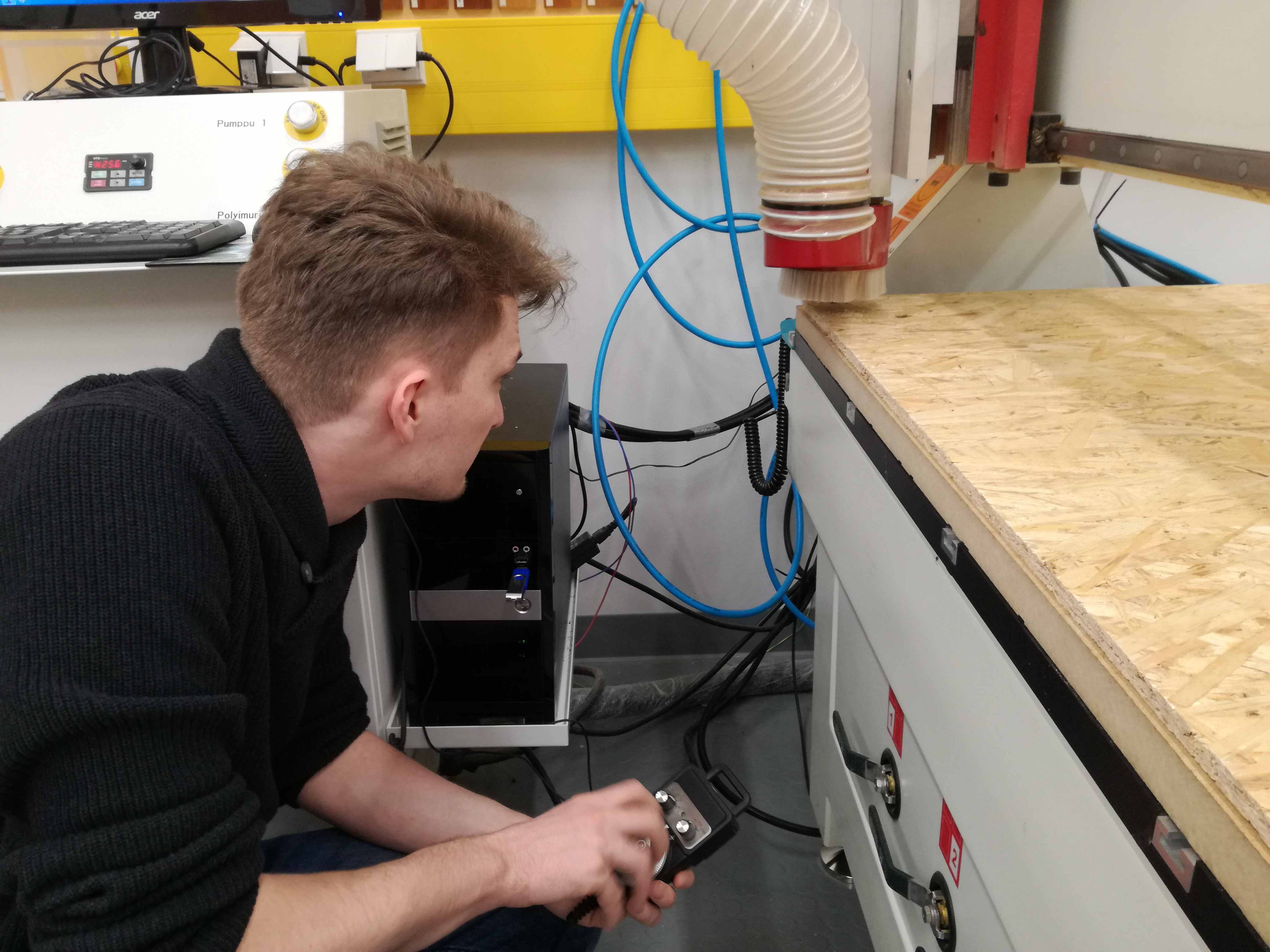
First of all, it is important to check if fuses on the wall are set properly. This part can be made by supervisor. Next, there are couple big buttons on Milling machine driver. Green is obvious choice . Third thing to turn on is vacuum pump, big switch.
Software is called NCStudio. In its options there are all following steps adjustable. It is an interface, where user can set all variables and adjust machine to mill properly. Most of the adjustable values are on the main screen. If not they should be found in Menu tab on the top.
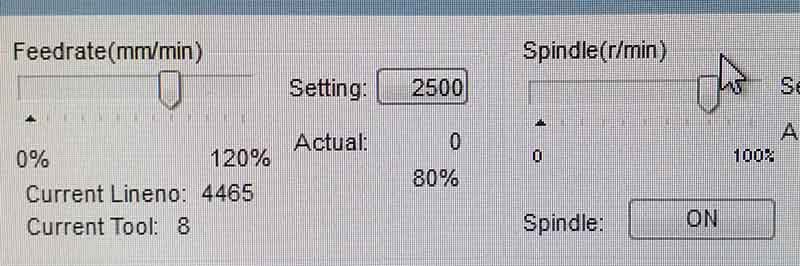
It is important to set right speed of rotation of the milling bit. NCStudio is superior over Fusion. Speed and feeds may be still changed even after setting them in Fusion.
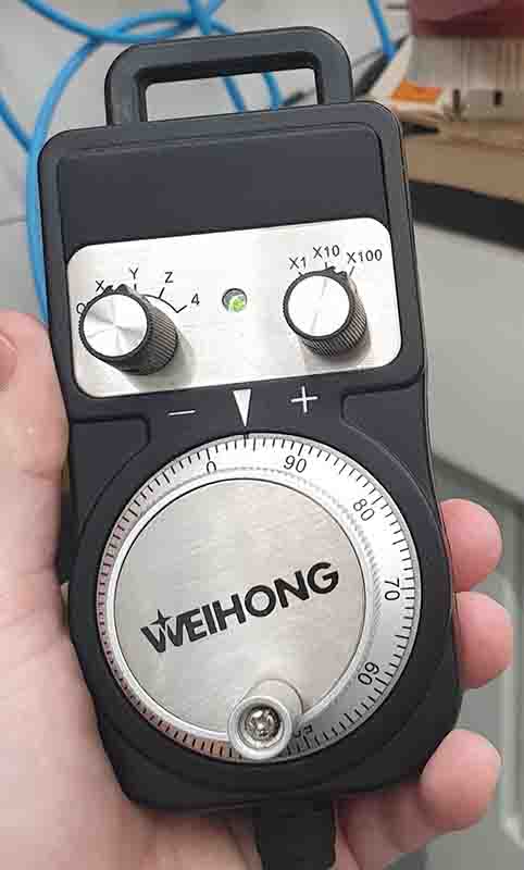
Spindle is moved using remote pilot. There are bigger and smaller steps available. Choose depends on the distance, which spindle has to travel. It is also possible to return to previously set (zeroed) points.
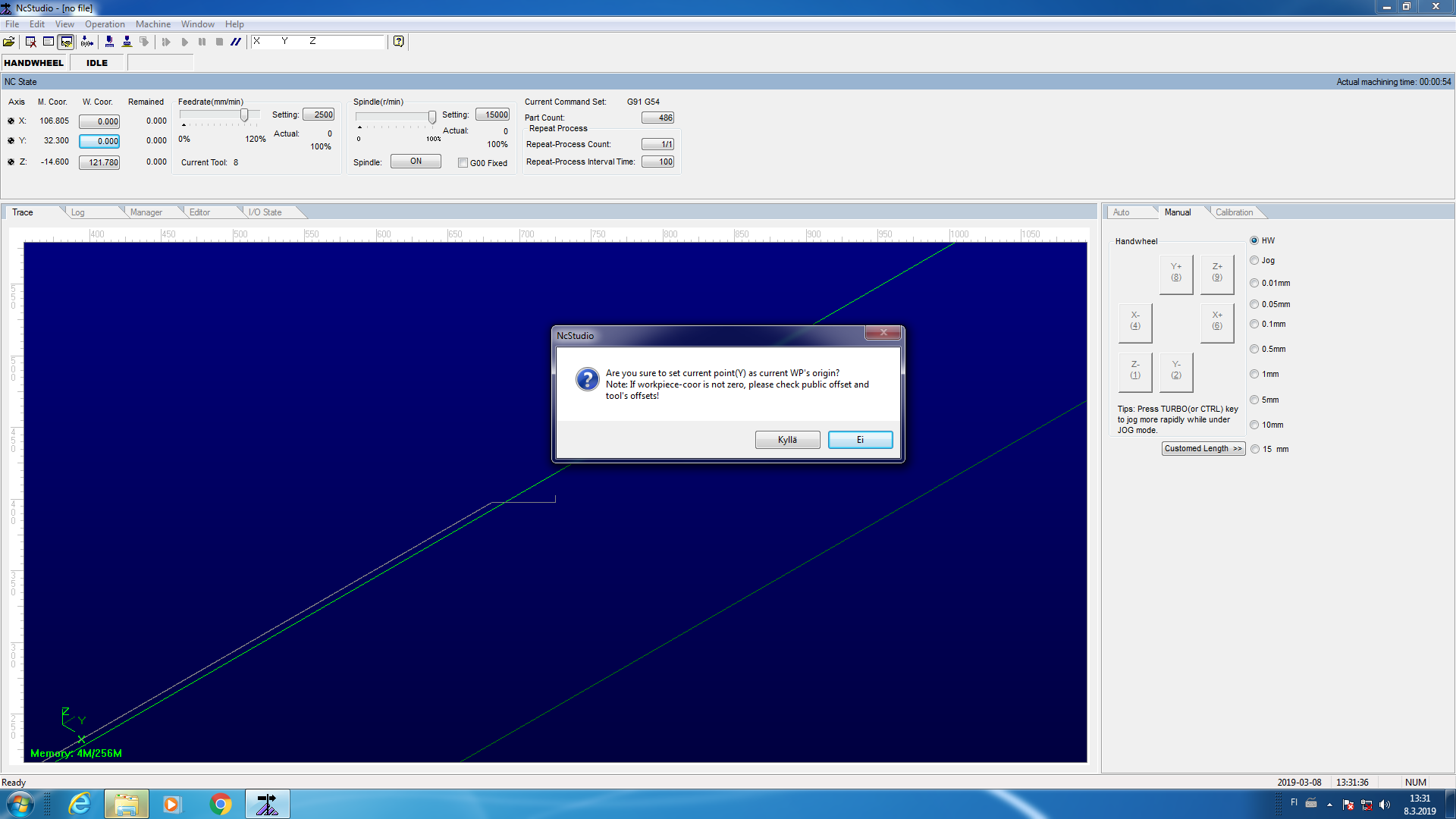
After beginning place is set using spindle it is time to zero it's location. Milling will begin with this point. It is quite important in terms of saving material and fitting designs.
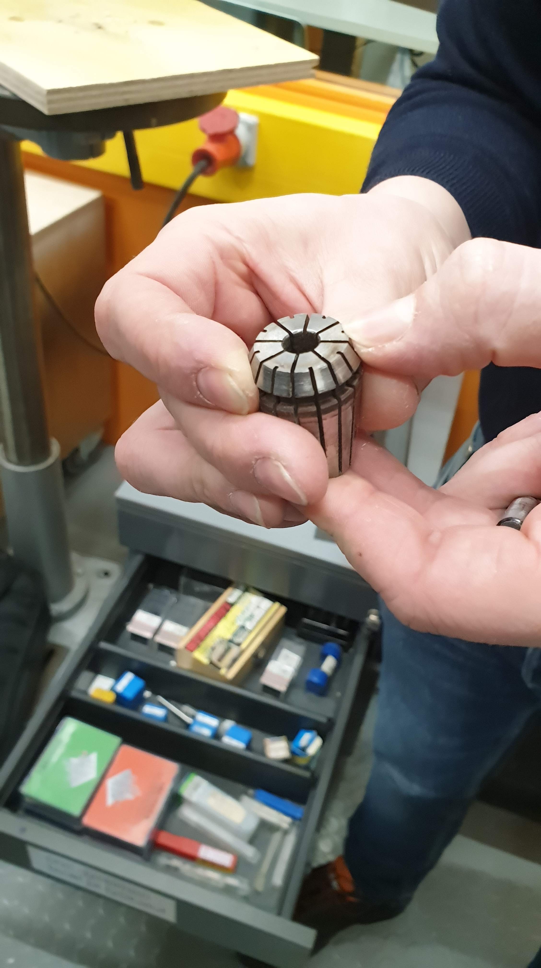
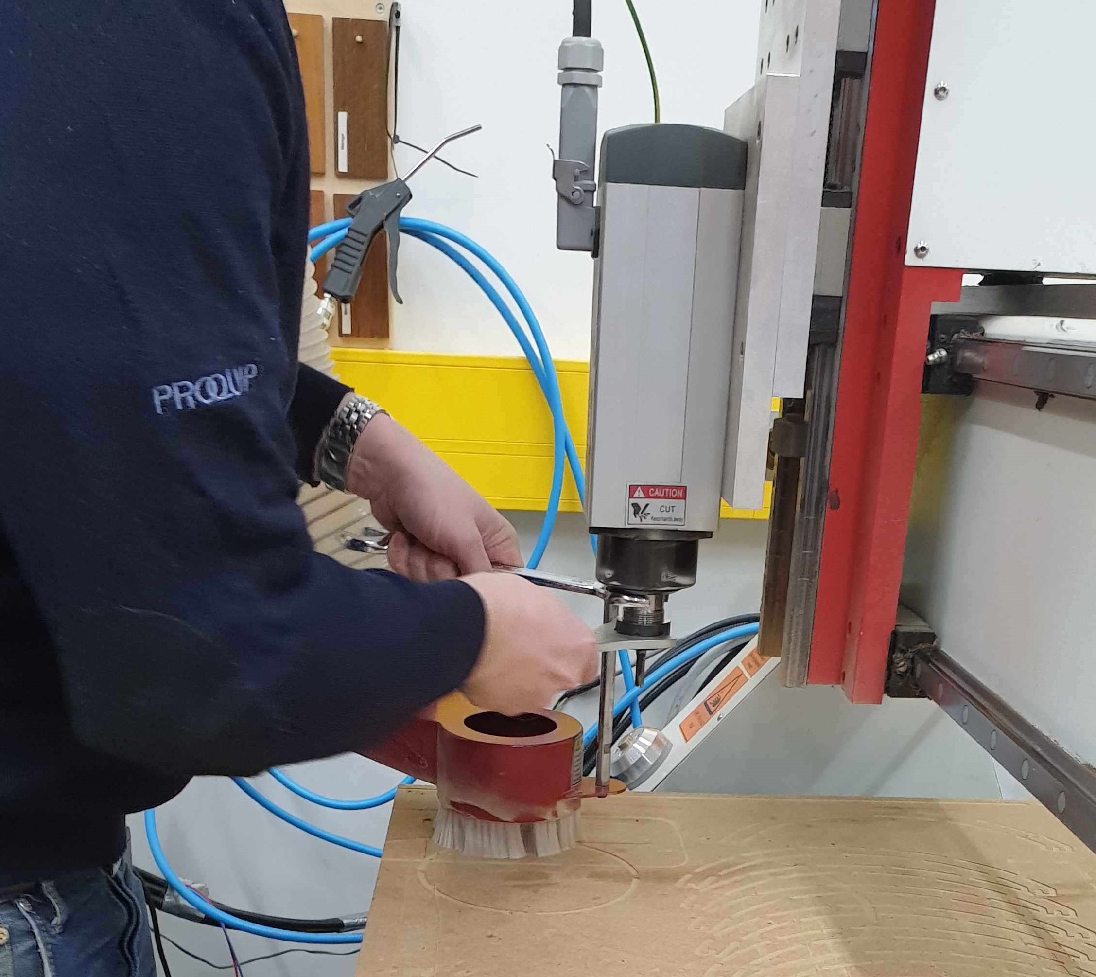
There are plenty of milling bits to be used. One screw has to be unscrewed in order to change milling bit. It is important to attach it tight. It is same easy, when using small-size milling machines such as ones used with electronics.
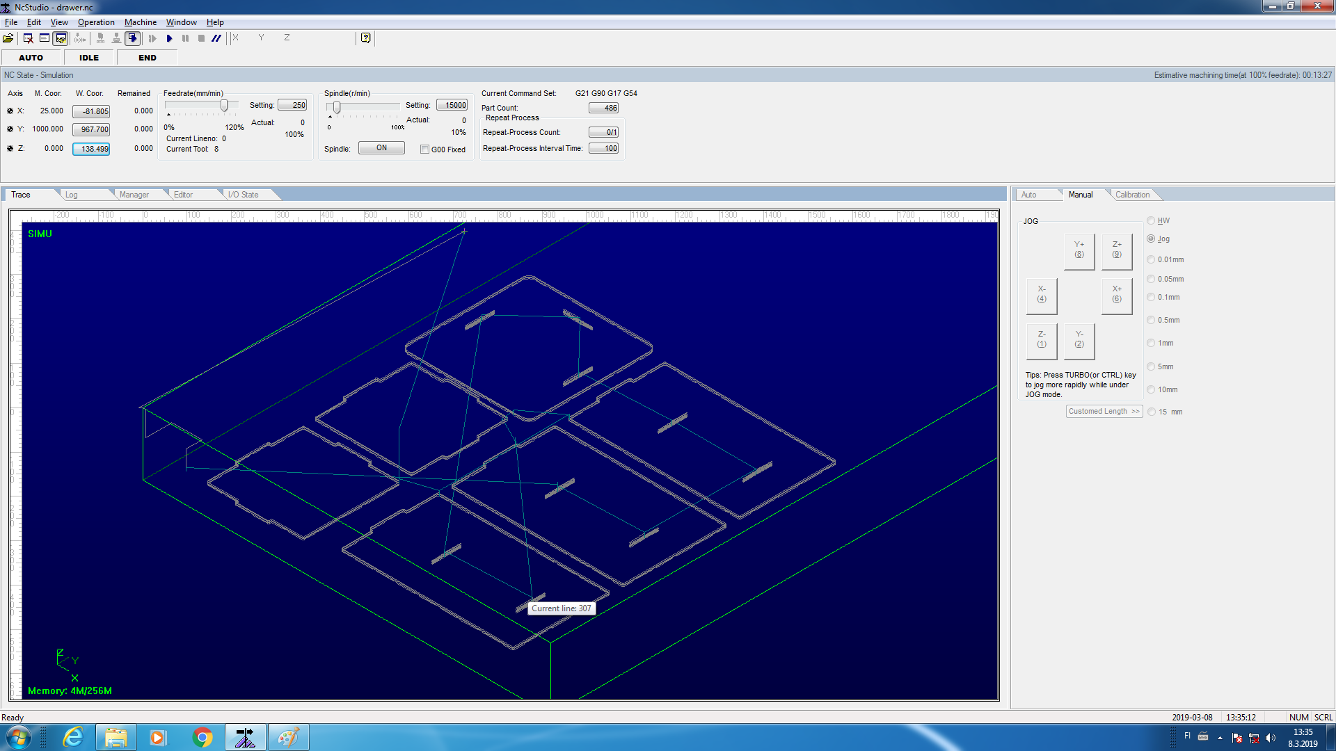
Despite of possible simulations in Fusion 360, there is once again possibility to simulate the process. In order to do it Simulation has to be chosen from the tab menu (NCStudio). Simulation is a good idea, it don't take much time and troubleshoot possible issues.
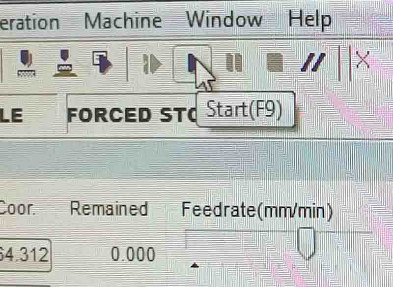
After everything was set correctly Grande Finale is just clicking on one button
 |
 |
 |
 |
 |
 |
 |
 |
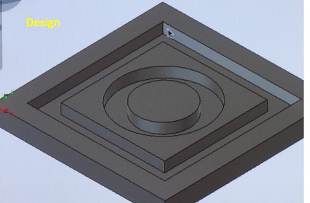
After designing our milling test object it was time ti mill it. Way to design was very standard. However, it was necessary to use another feature of Fusion 360 - Manufacture tab. Manufacturing process will be explained in personal assignment part.
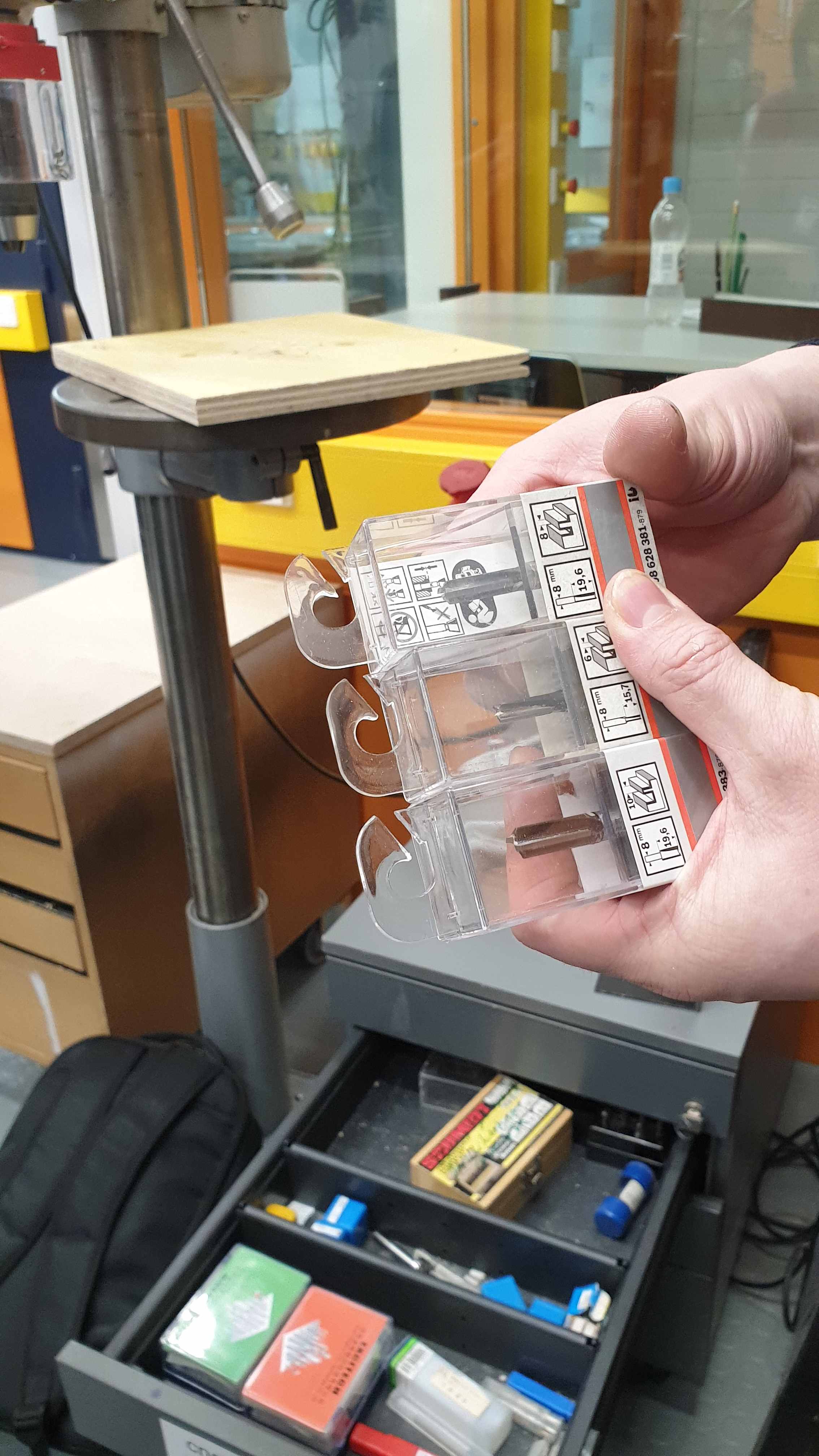
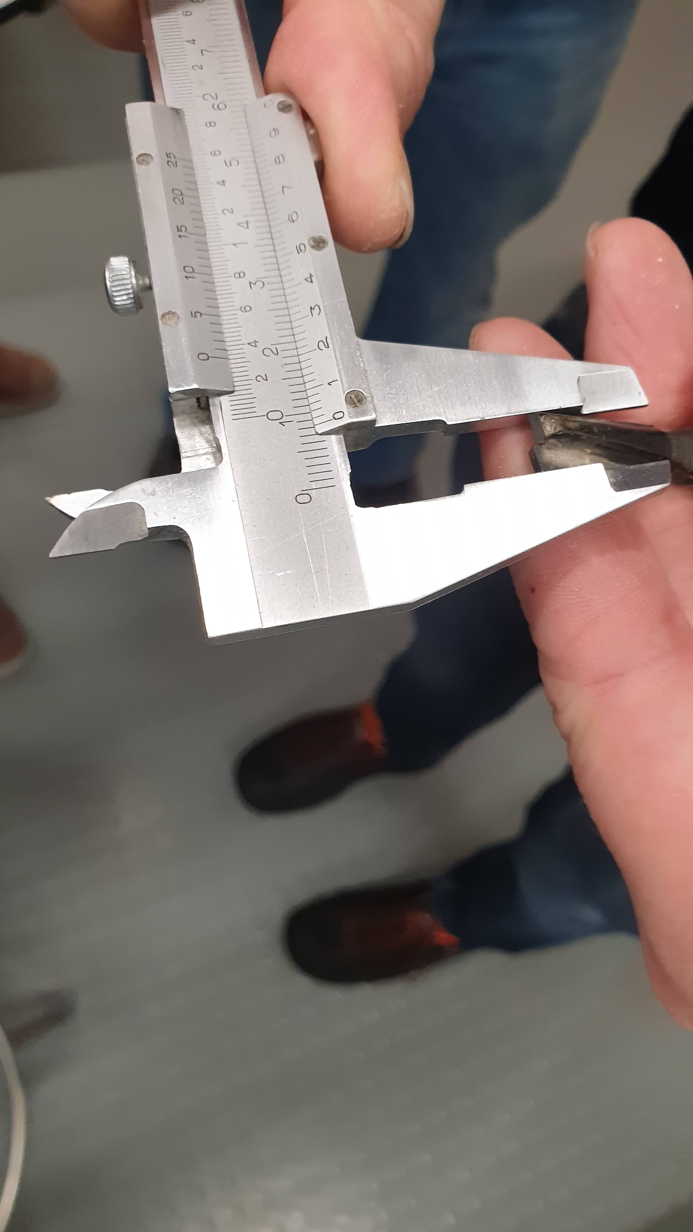
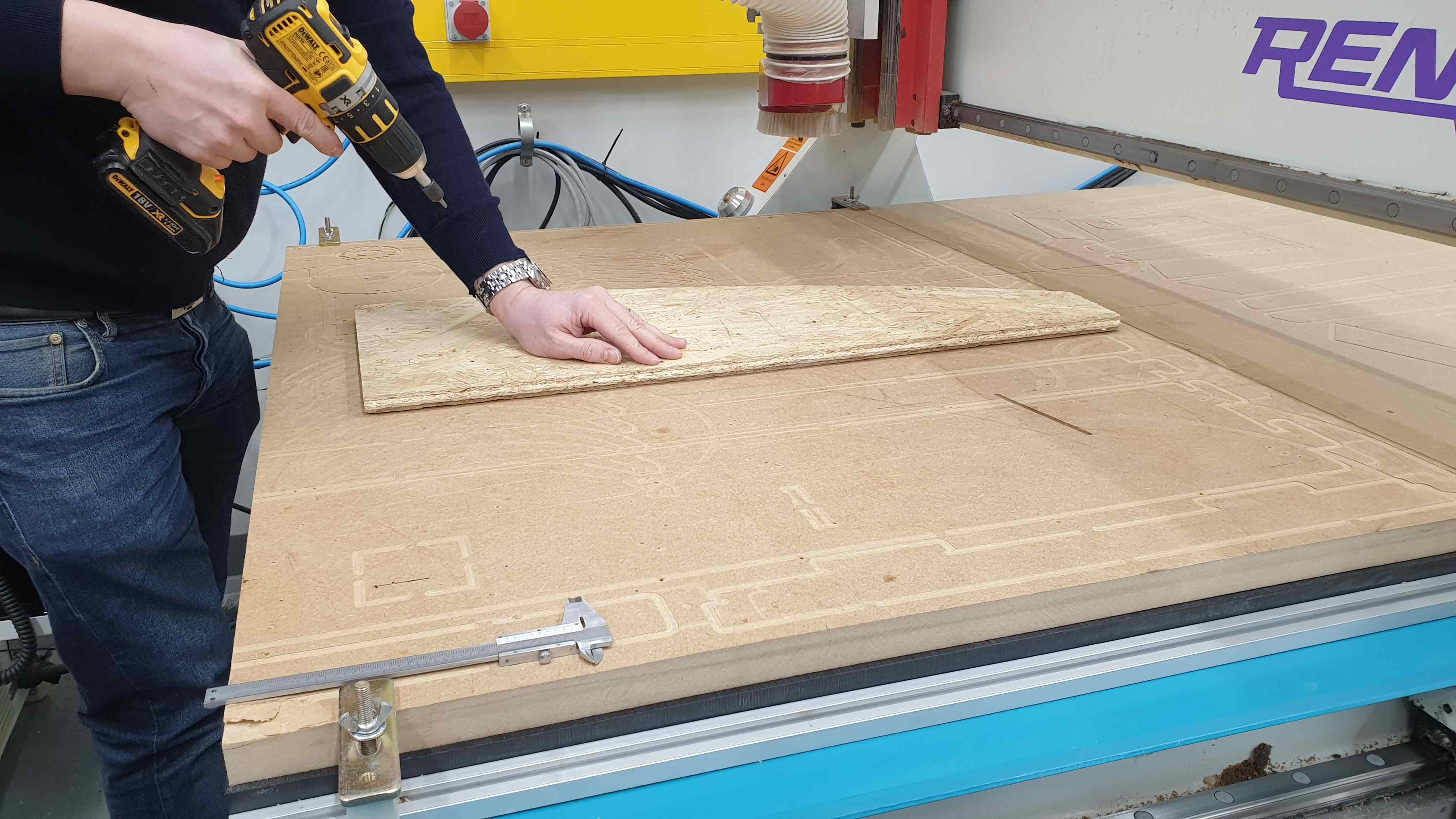
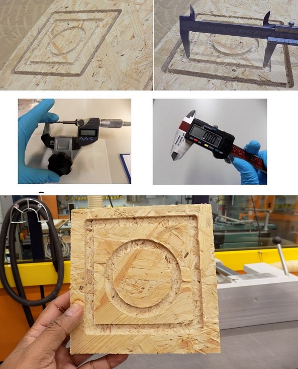
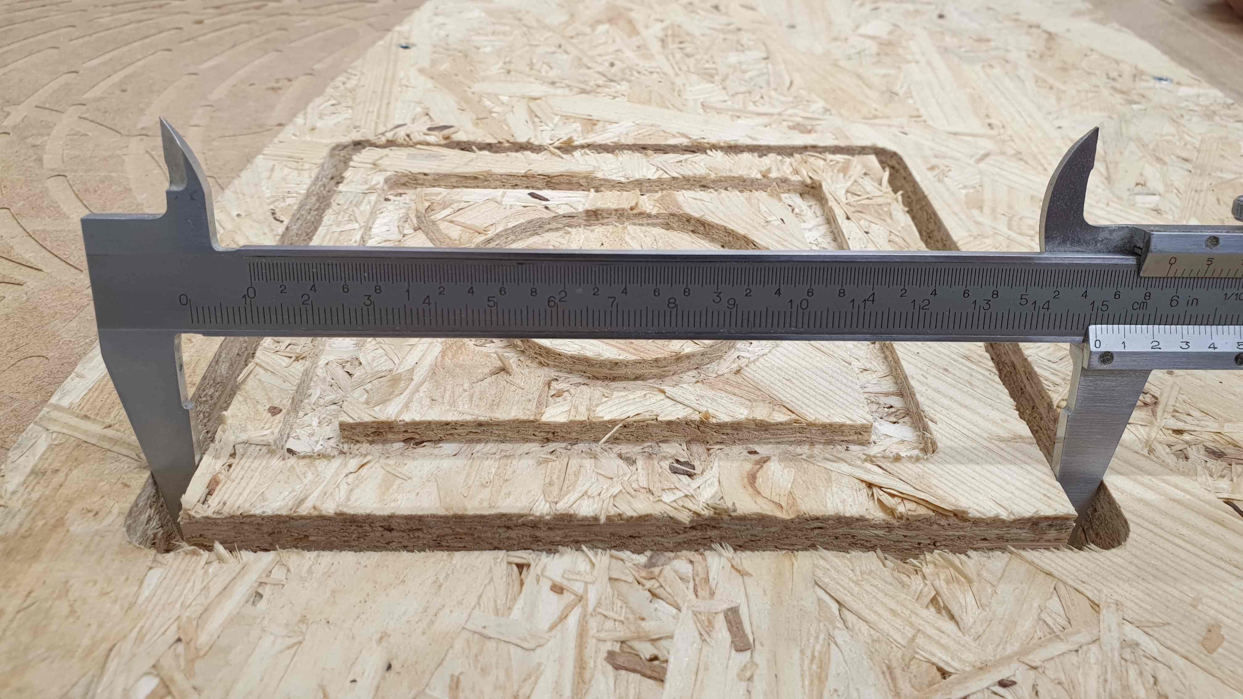
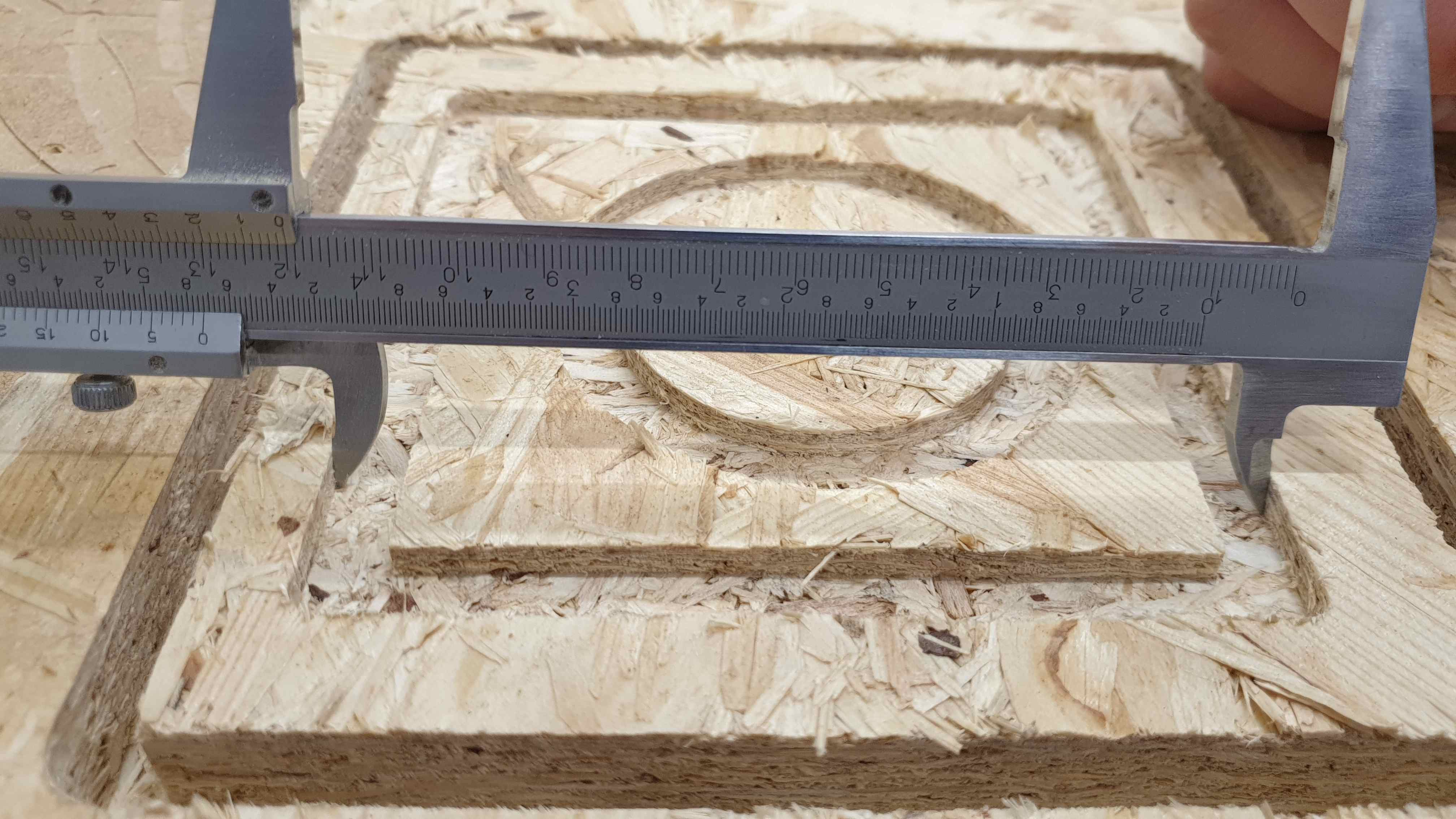
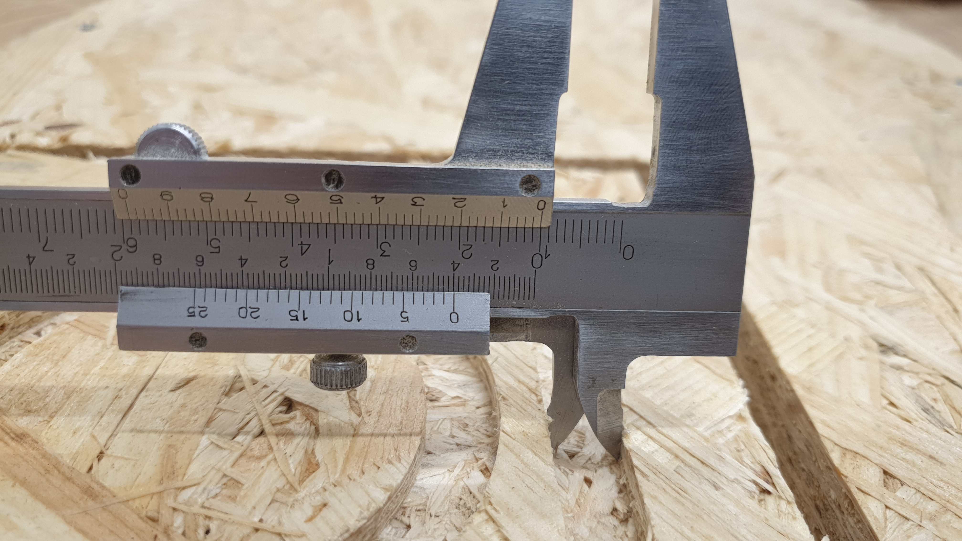
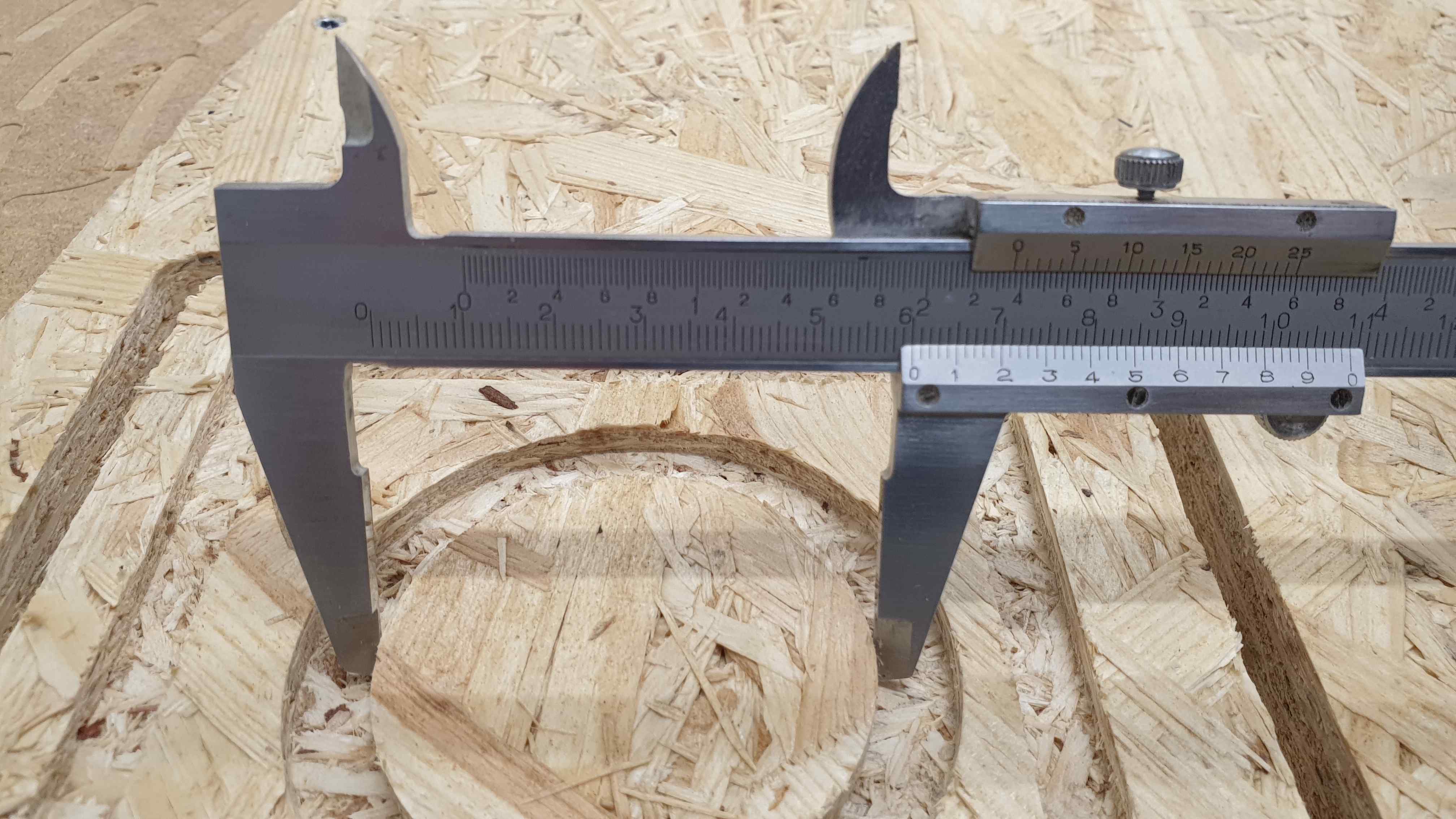
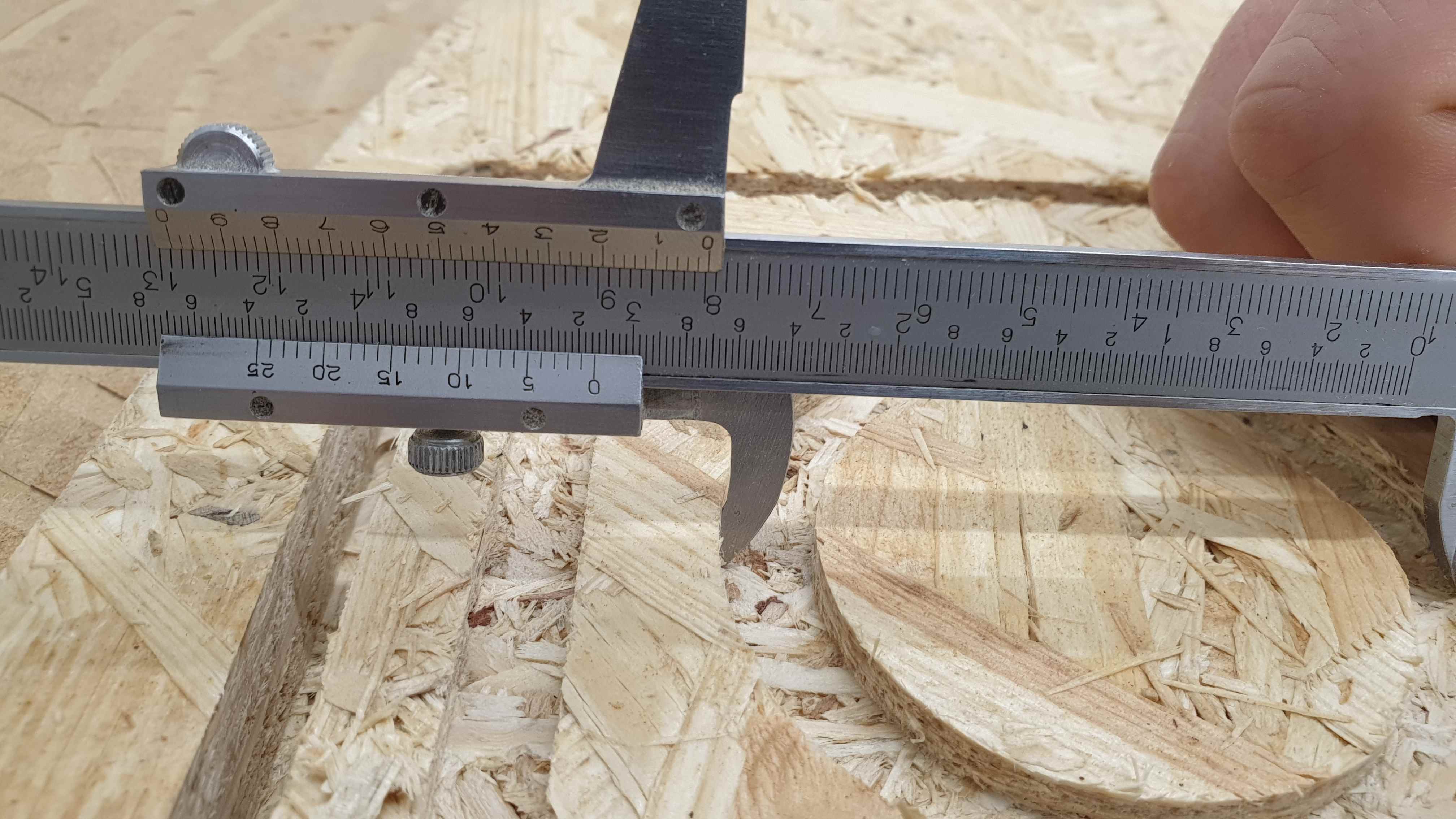
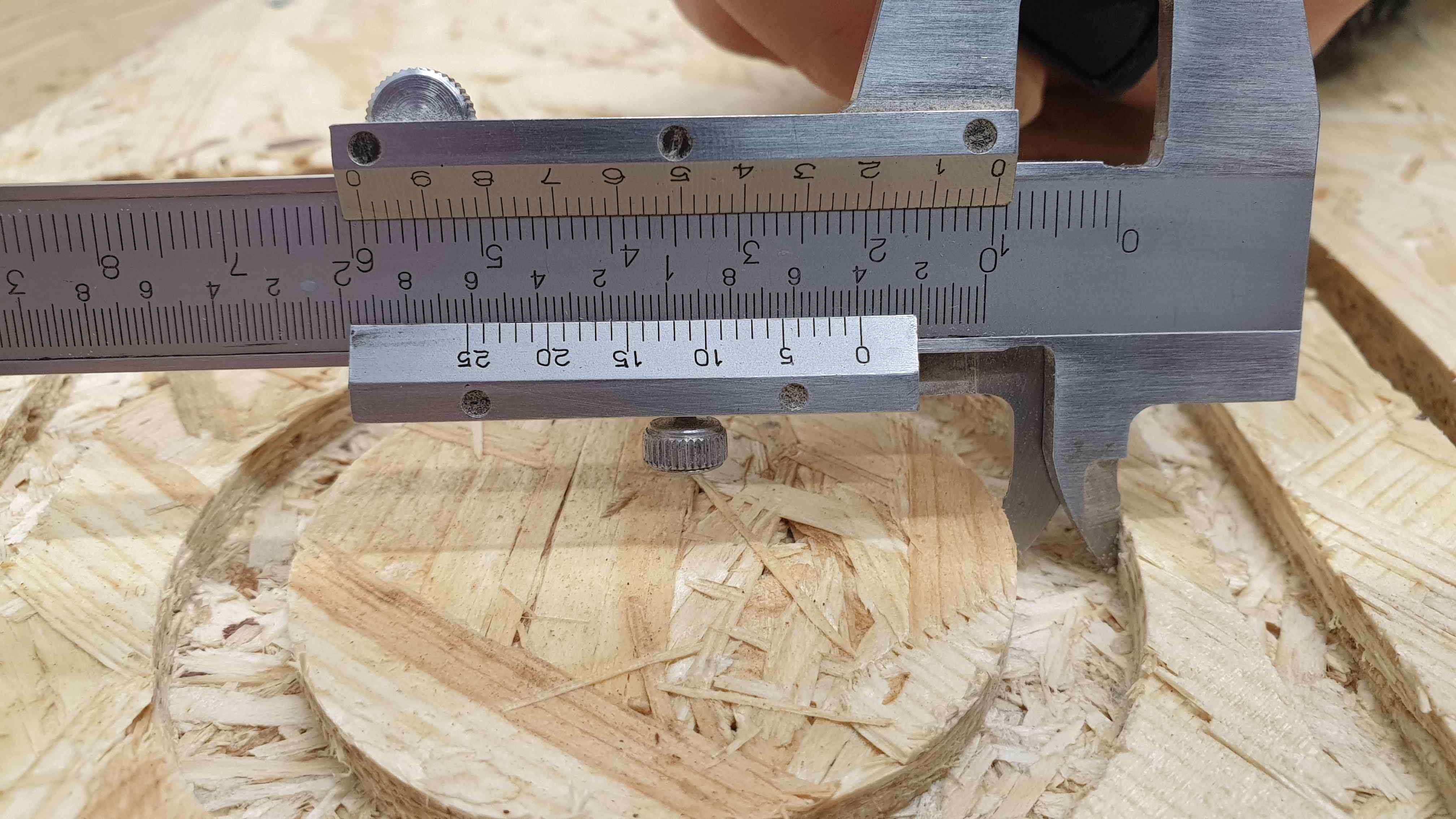
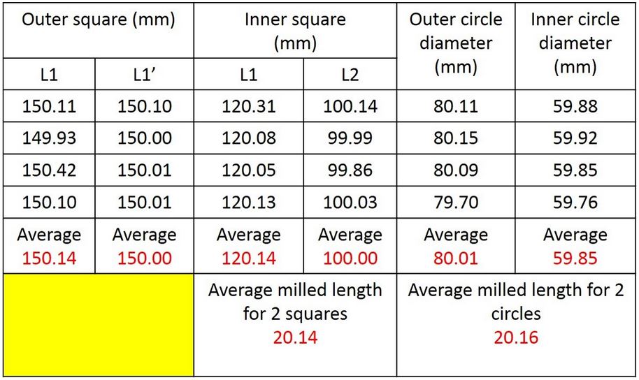
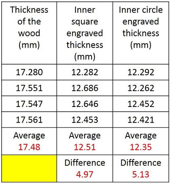
For manufacturing purposes we used: flat milling bit of 8 [mm] width, feed rate of 80% (from 6000 mm/min to 4800 mm/min). Spindle speed was set to 80% (from 15 000 RPM to 12 000 RPM). We choose 18 mm thick OSB board. In case of origins we set them both manually and them automatically, XY - position was chosen in a way not to overlap with screws holding the piece. We cut it and measured it.
  |
  |
  |
Individual Assignment
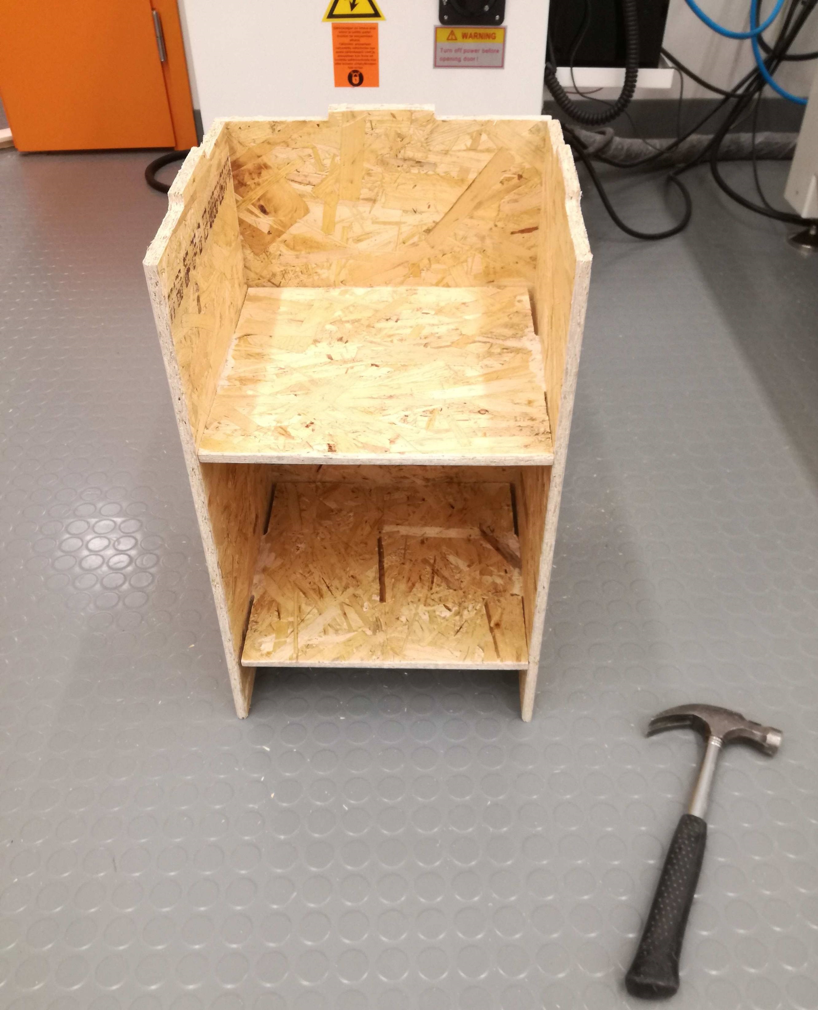
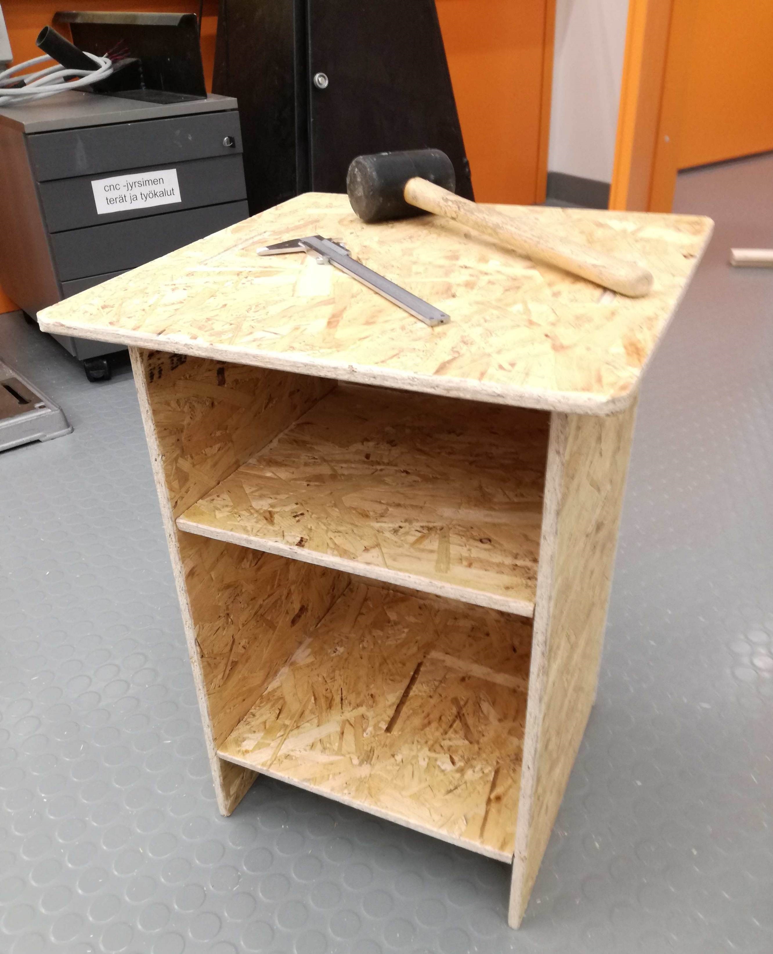
I had this idea to make a night drawer. I even had the shape in my mind before even starting designing it with Fusion 360. Spoiler alert: In the end it turned out that OSB is rather annoying material and its usage as real furniture is really limited. There are thorns everywhere, you cannot really polish the surface to be safe. To describe OSB benefits I will use ancient-common knowledge about cheap wine. "Cheap wine is good because it is cheap and it exist". OSB is a bit similar, it is cheap and it exist - so it can be used for testing purposes.
Designing
As I mentioned previously - Fusion 360 was my choice. I will not focus much on creating sketches and dimensioning as it is well-described in previous assignments such as Computer-aided design, Computer-controlled cutting and 3D scanning and printing. Nevertheless, this time I found one function extremely handy. I will explain it shortly.
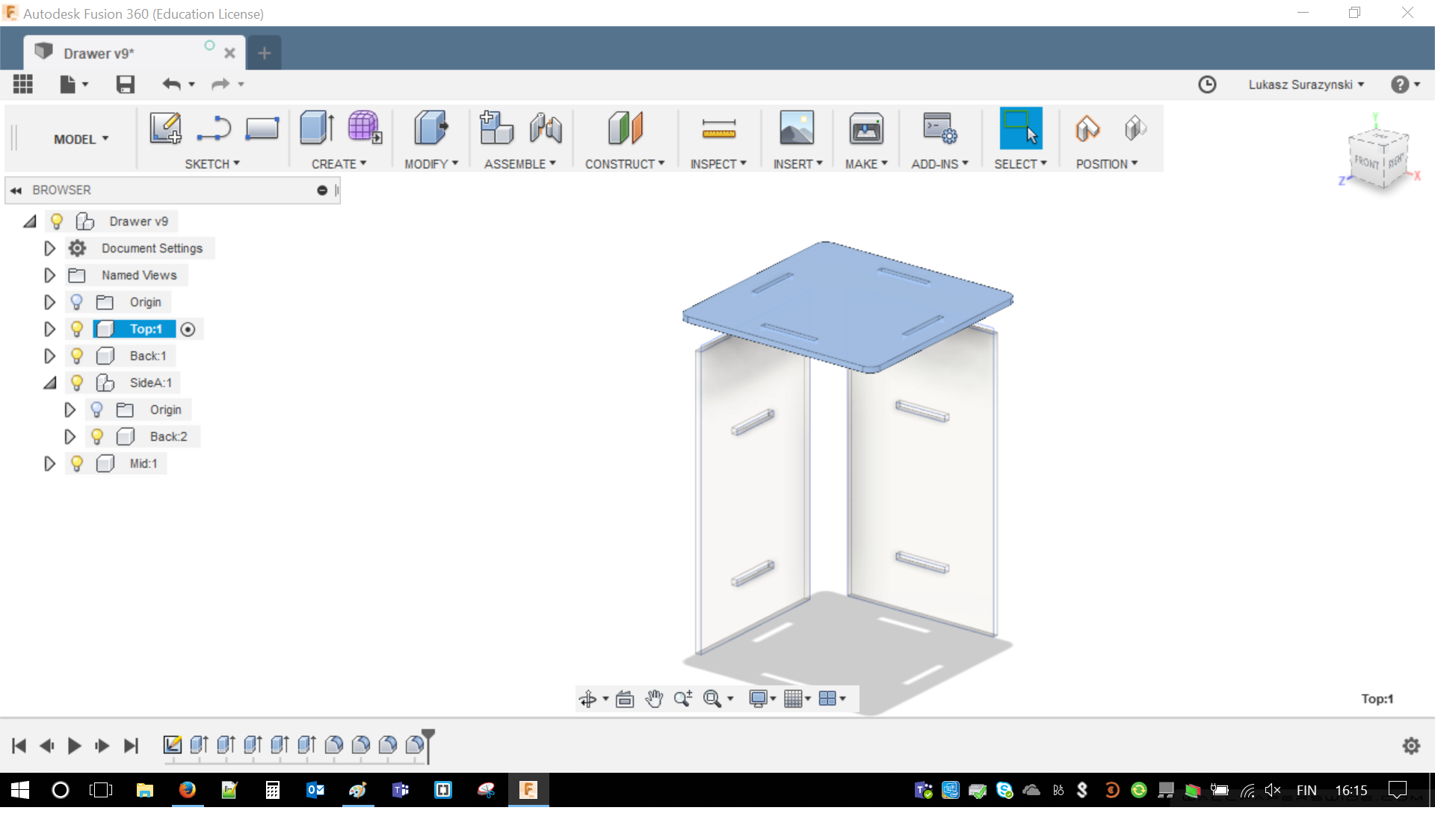
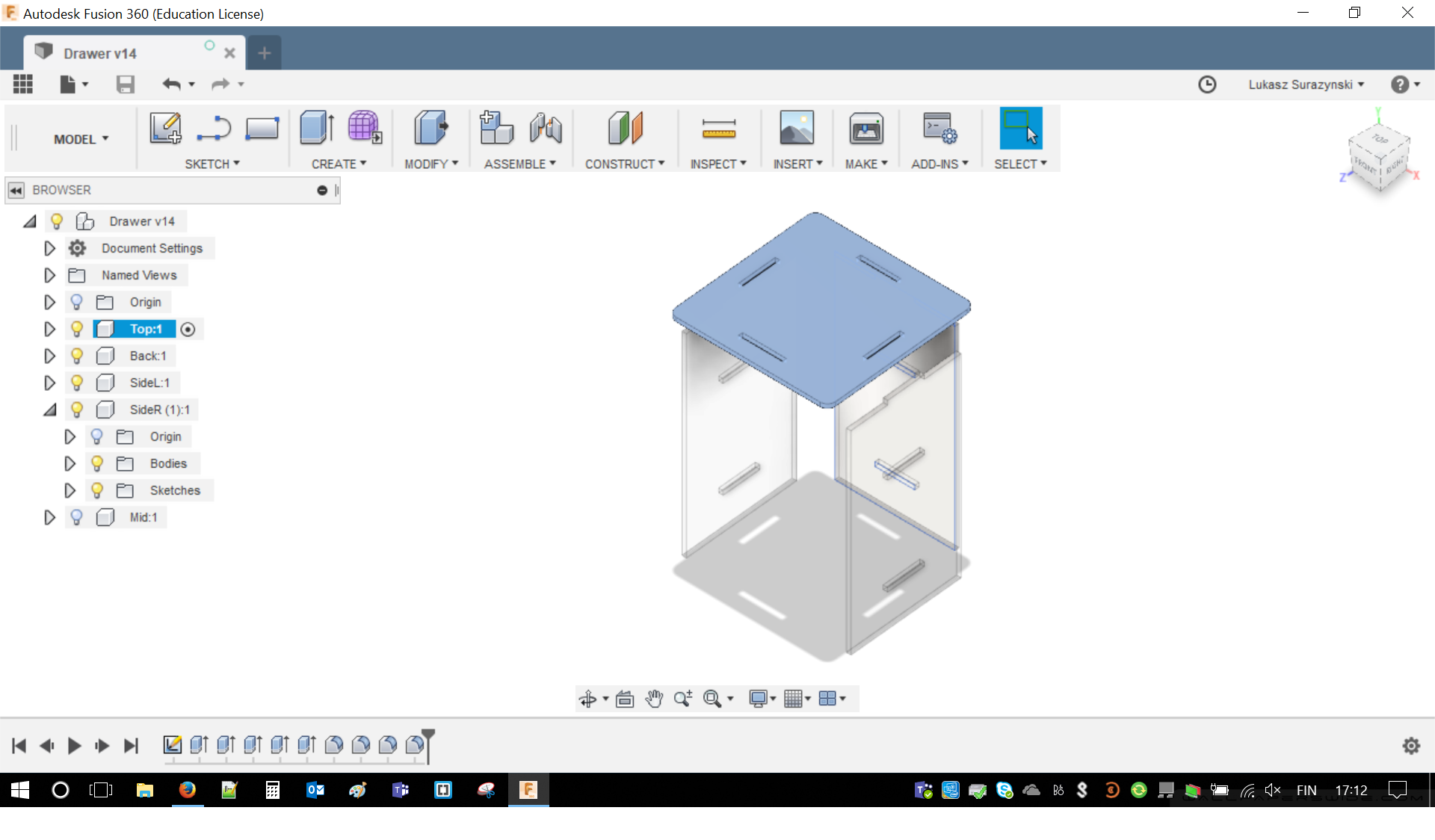
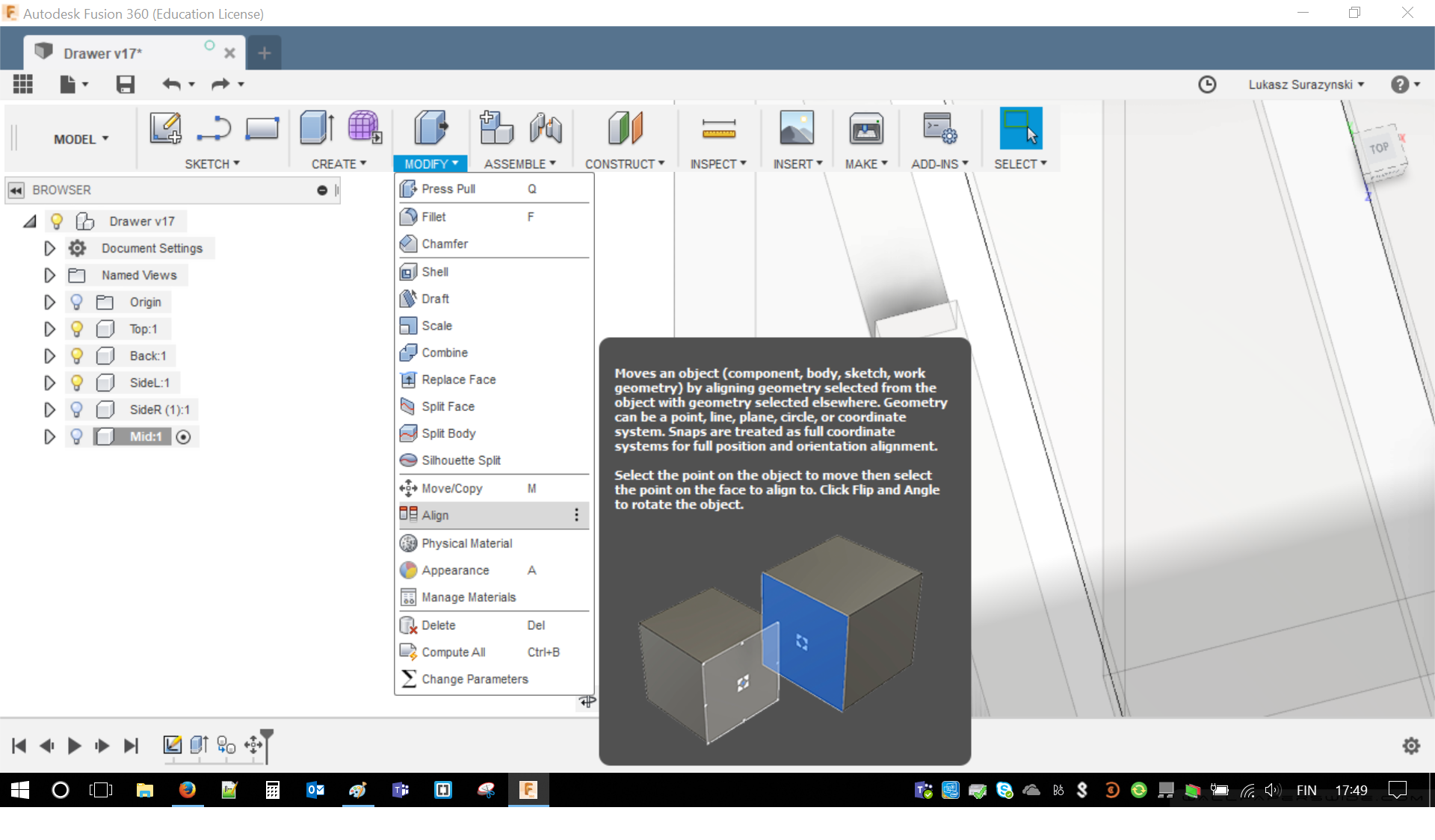
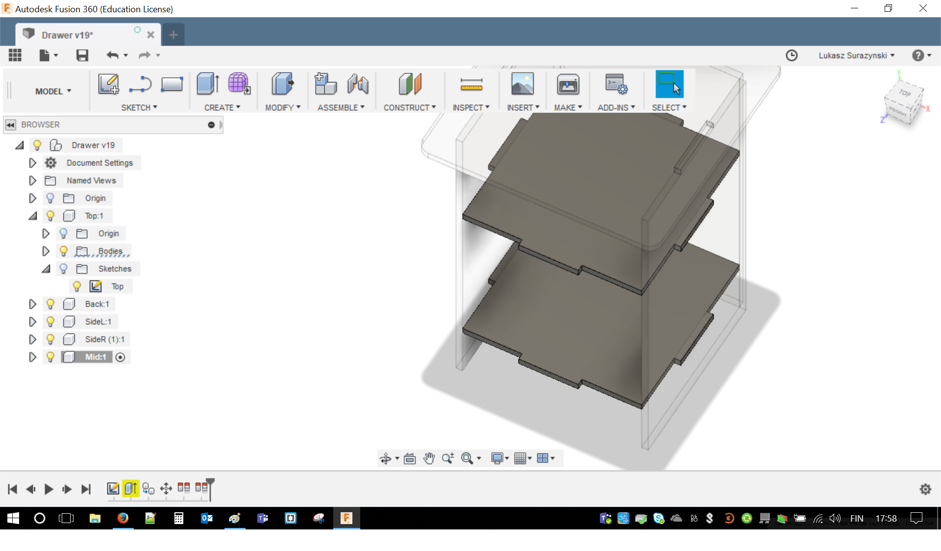
After having 4 out of 6 pieces: Top, Left Side, Right Side and Back it was time to create two shelves. It was fairly easy as all of those are used with similar tools. The questions was how to troubleshoot it and check if dimensions are right. This is, when Align tool is being crucial. In order to reach it MODIFY/ALIGN has to be opened. With two simple mouse clicks I was able to align, rotate, position, move, and squeeze pieces inside of each other.
It helped me to check if my dimensions are right and correct sketches almost instantaneous. Below photo of alignment of the shelves. Tolerance of milling is less than 1 mm. This means I don't really need to leave any free spacing (comparing to cutting with laser and kerf)
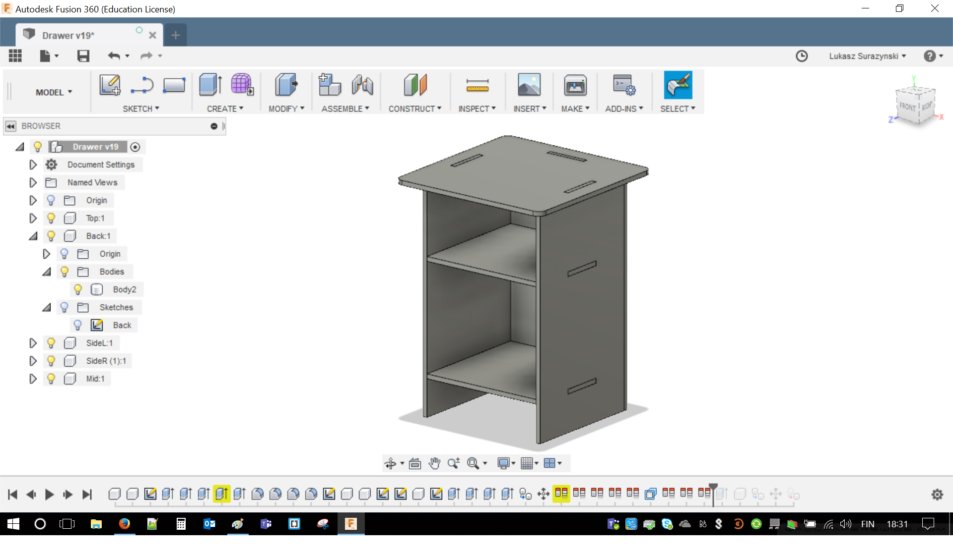
With a bit of hide and seek. I was able to put together all of my drawer. The only thing difficulty is to be precise. There must be at least a bit of imagination. If part was misaligned it was my fault rather than software. I condemn. In general it was logical and I really enjoyed the results. I guess playing chess might help if you are having troubles using Align.
Manufacturing - with Fusion
Time for some real things to happen. For Computer-controlled machining it is crucial part. Fusion 360 has special Tab for this purpose. With a bit of fortune I managed to document everything with screen shots. Just for my own entertainment I rendered my parts. Right now its is cherry tree but I was considering mahogany. Credo for today was "make it big". For this chapter images, simply click on them to open enlarged versions.
Let's start with disassembling the drawer and putting pieces next to each other on XY axes. Nice color of cherry tree may be noticed. I tried to put them reasonably close to each other so I do not create a lot of waste material. In the meantime FabLab Library should be imported to the Fusion. Simply go to MANAGE/Tool Library and find the file.
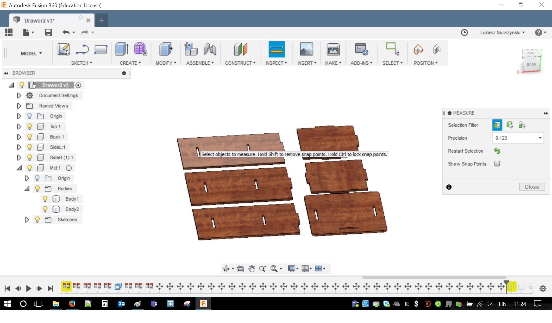
Time to choose Manufacture Workspace from the first tab. This is just beginning. After that new options are available. I think I mentioned that I already started to like Fusion, developers kept it clear and simple.
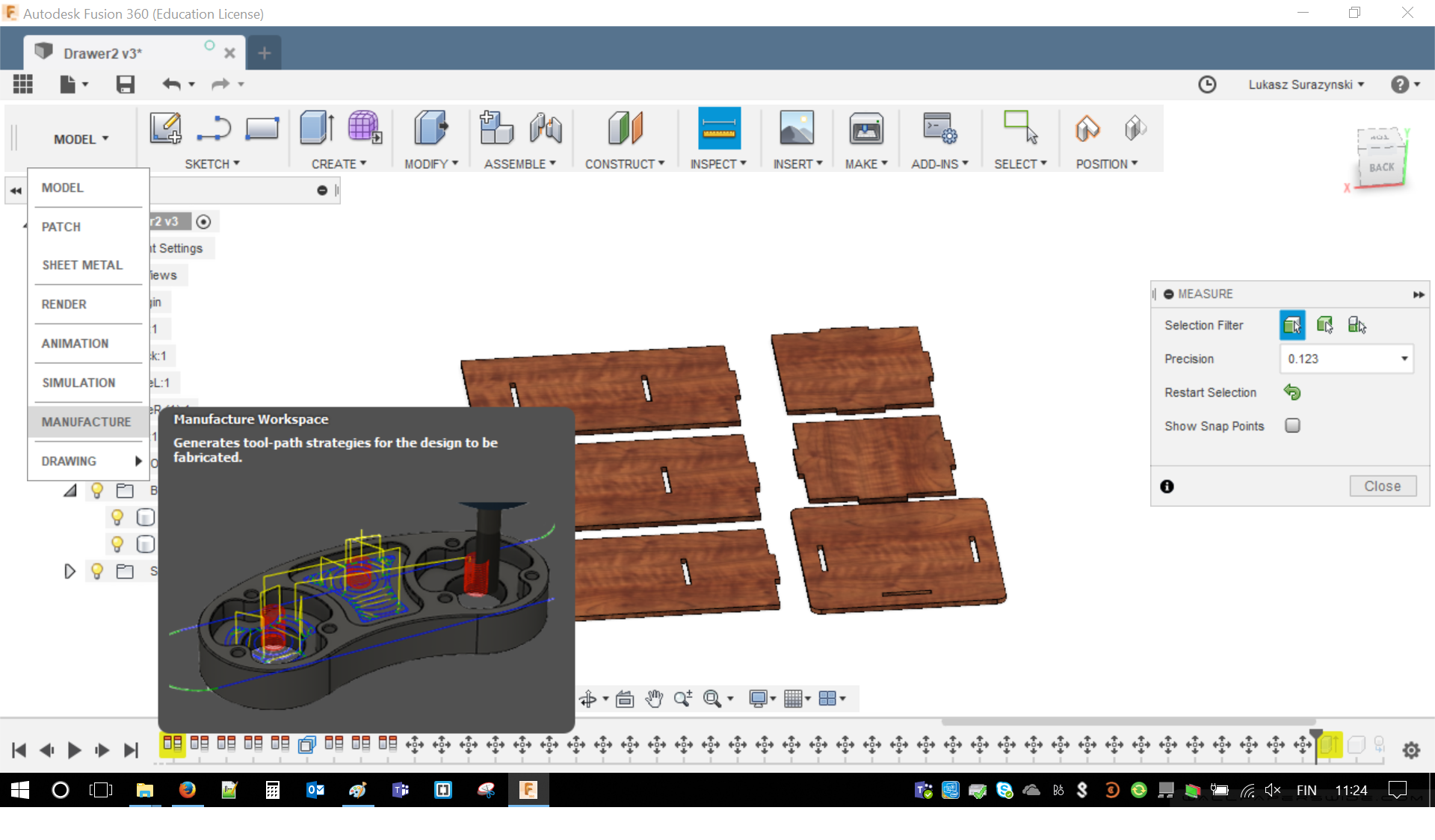
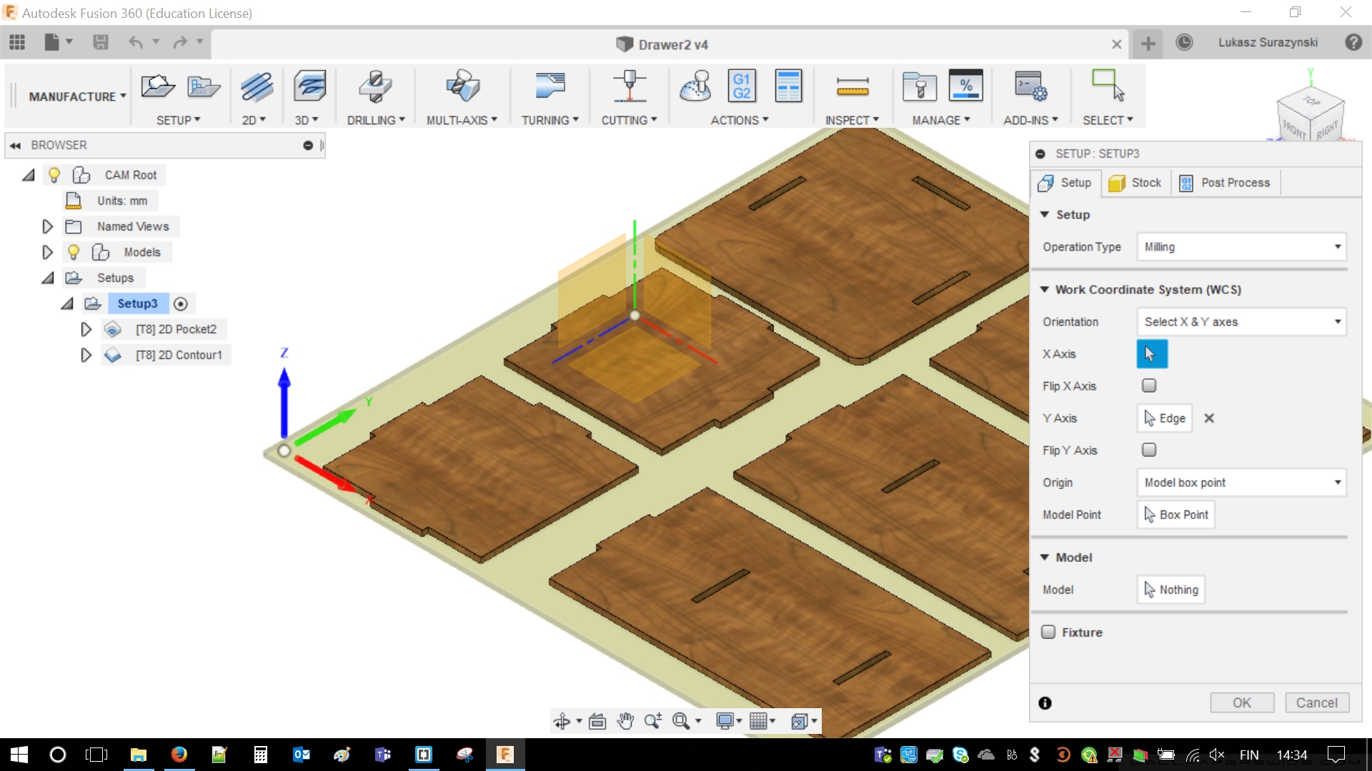
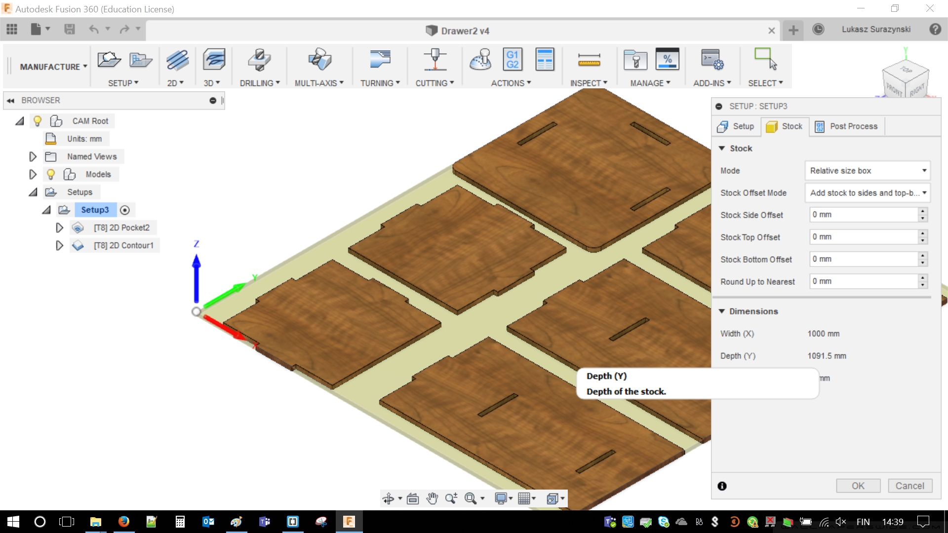
Next step is to enter Setup/New Setup. This will open new window with additional options with three tabs: Setup, Stock and Post Process The last tab is not relevant. Below two remaining tabs.
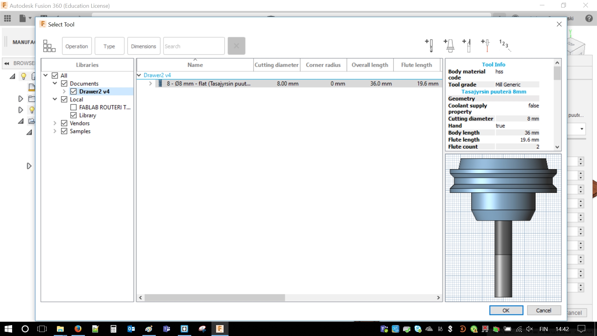
In the meantime it is time to choose milling bit. In this case 8 [mm] was the choice, it was available after importing FabLibrary.
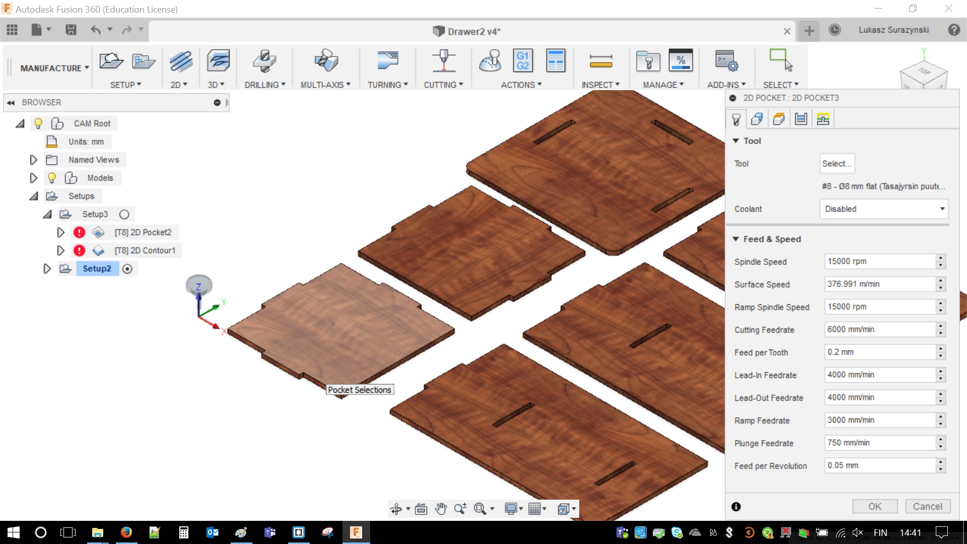
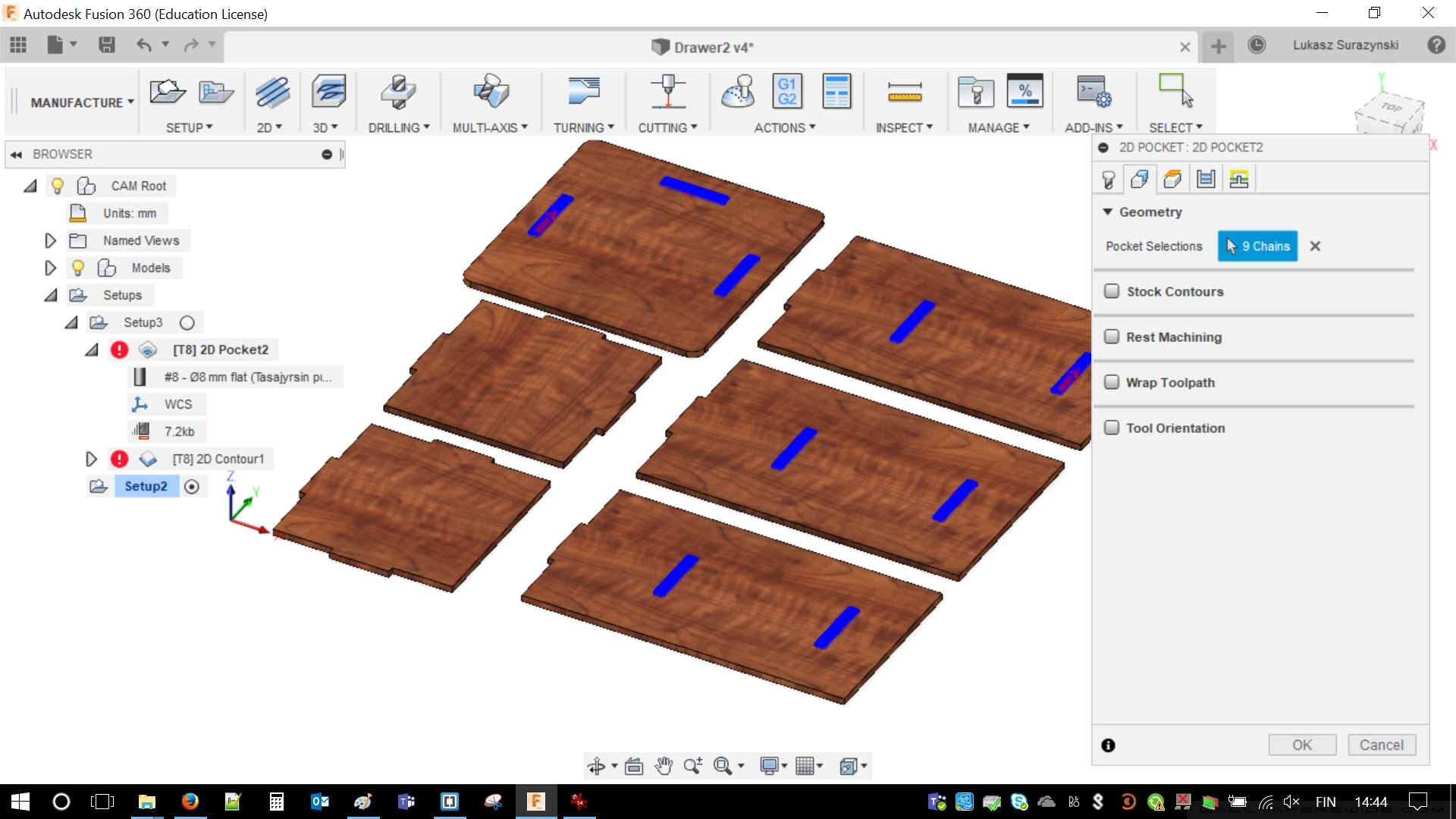
It is time to create 2D Pockets, those are available from 2D/2D Pocket. It will create holes inside of material. Window has 5 tabs: Tools/Geometry/Height/Passes/Linking. Screenshots are available below. Most of the options are available from the library. It is necessary to highlight places, which should be cut out. Clearance hight is 10 mm, where Retract high is 5 mm (measuring from stock top). In passes it is important to use even step downs. Next following images are related:
As I previously mentioned the right tool has to be selected. 8 mm milling bit was my choice. This is questionable as smaller milling bit would probably be more precise and I had to remove less material from the holes. In the end I decided to use quicker milling.
Time for Geometry tab. In here I localized all the nine holes and highlighted them holding SHIFT. Results are visible below.
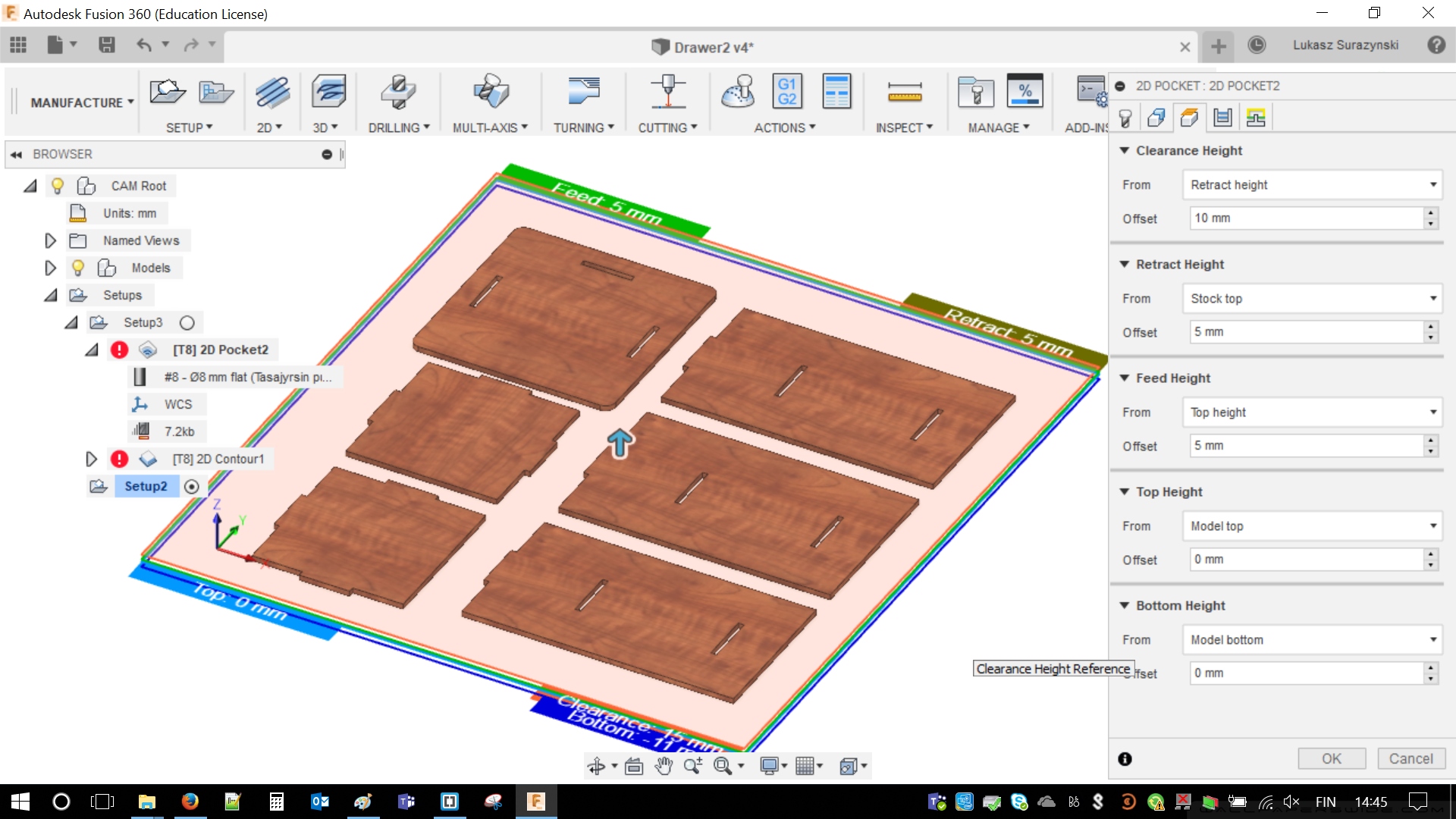
Next tab, which is Height should be set in following way: 10 mm / 5 mm / 5 mm / 0 mm / 0 mm. There is a screenshot for better understanding.
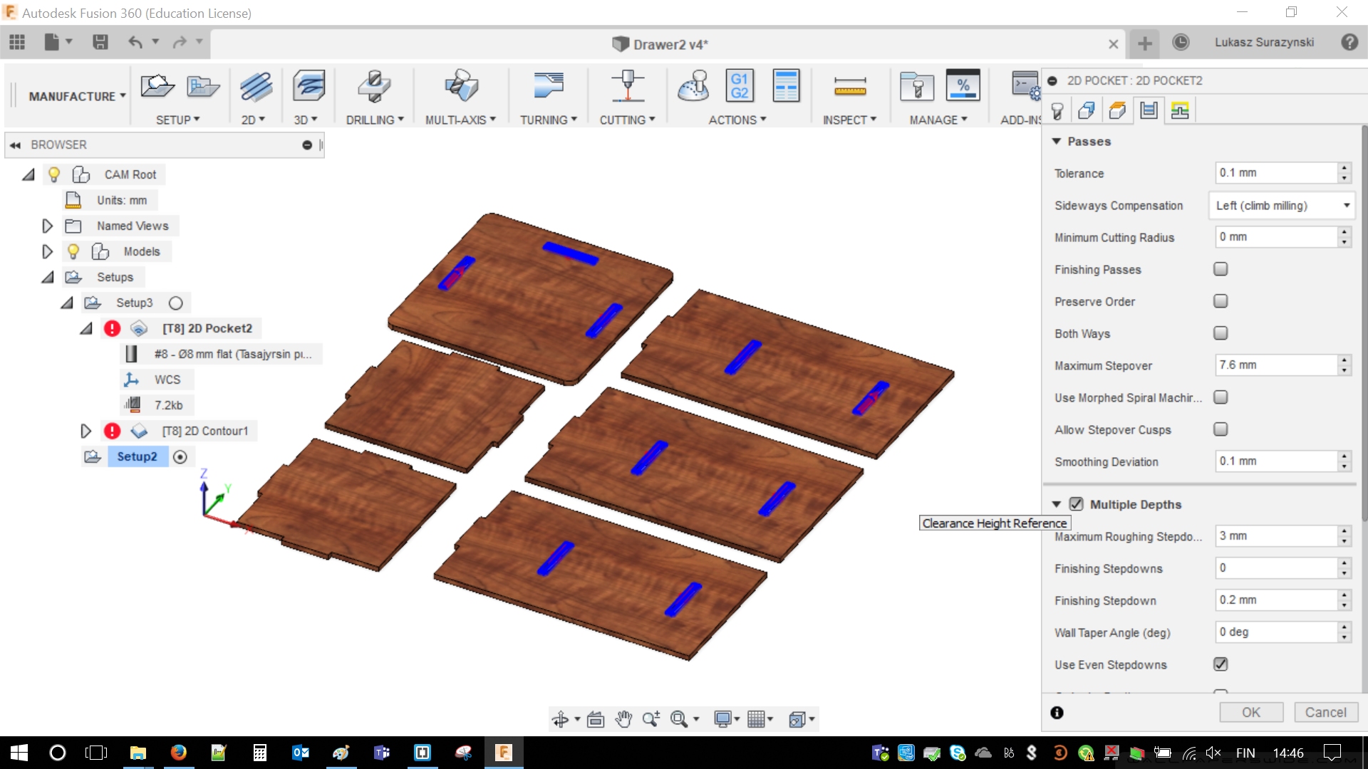
Next tab, passes. In general the most important value is in Multiple Depths. Even step-downs has to be used with some maximum roughing step-down (I simply used 3 mm). It means that step-downs will be adjusted as close to 3 millimeters.
In the last tab: Plunge has to be chosen as Ramp Type and that is about it. The only thing remaining is just confirmation with
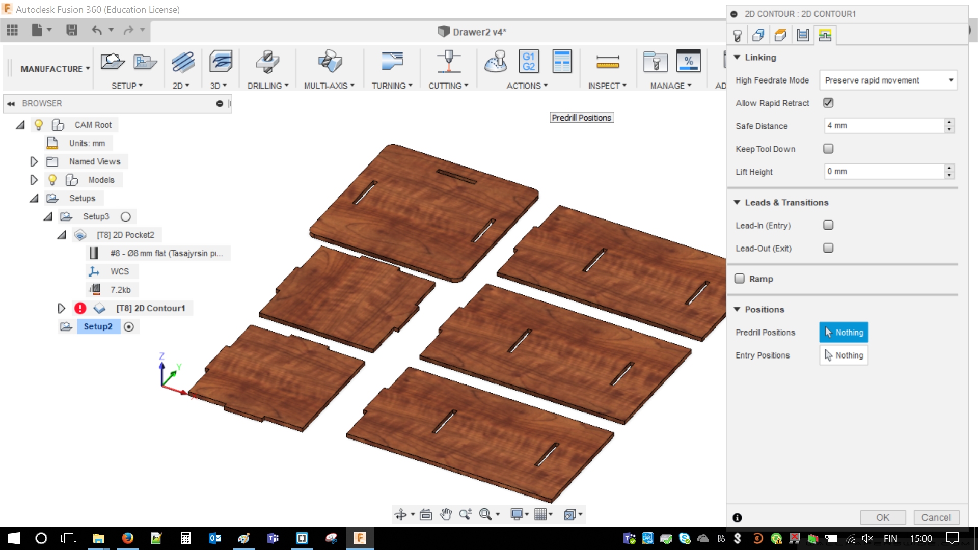
Now it is time to cut Contour from 2D/2D Contour Steps are very similar in previous part (Pockets). The tabs are totally the same. Let's start by choosing proper toolbox. As options are very similar I will focus on the only on things, that has to be changed.
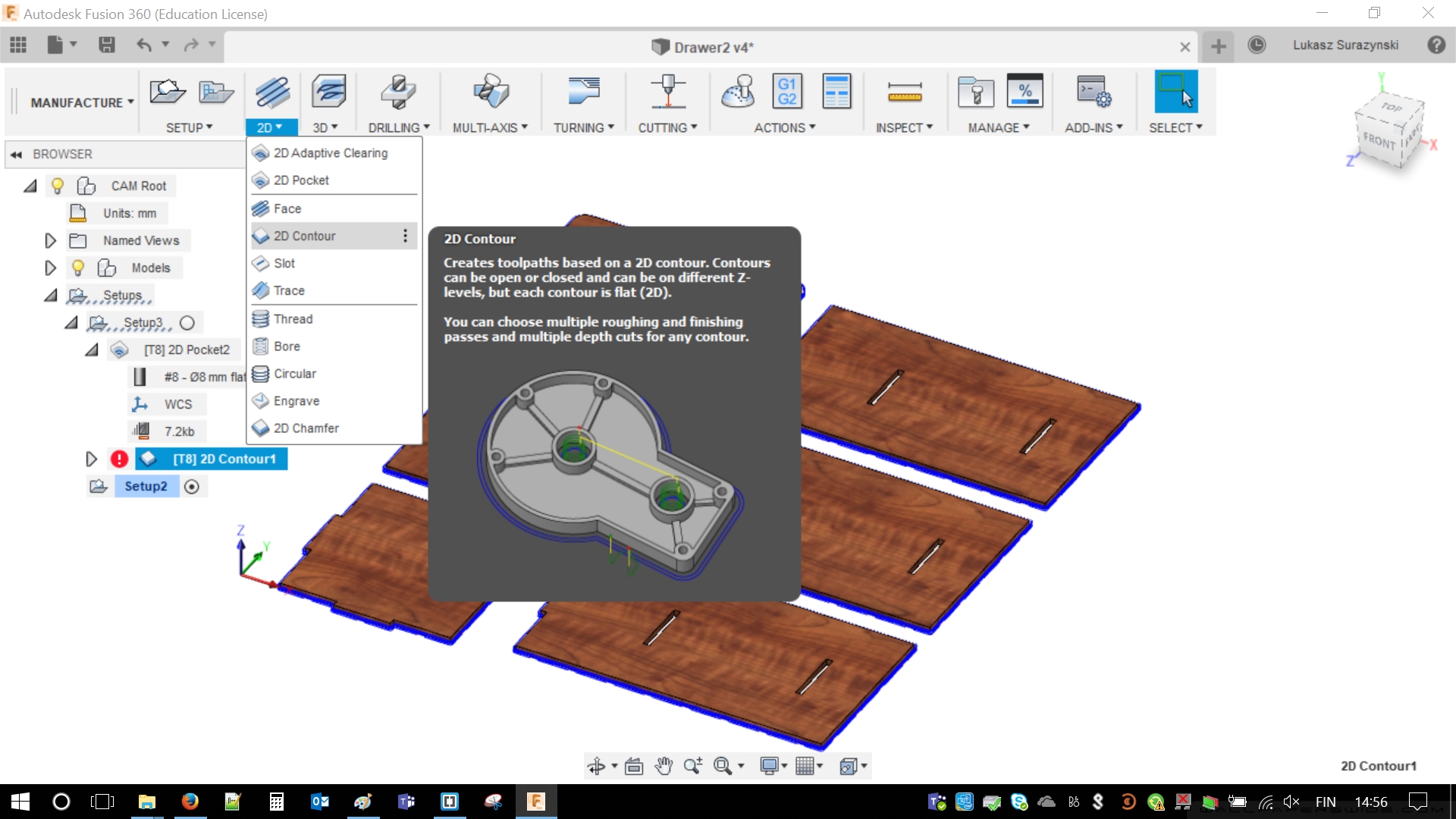
Milling bit was chosen before. It remain the same. Once again in Geometry there is a bit of work. Contours has to be marked. Six pieces, six contours. Simple math.
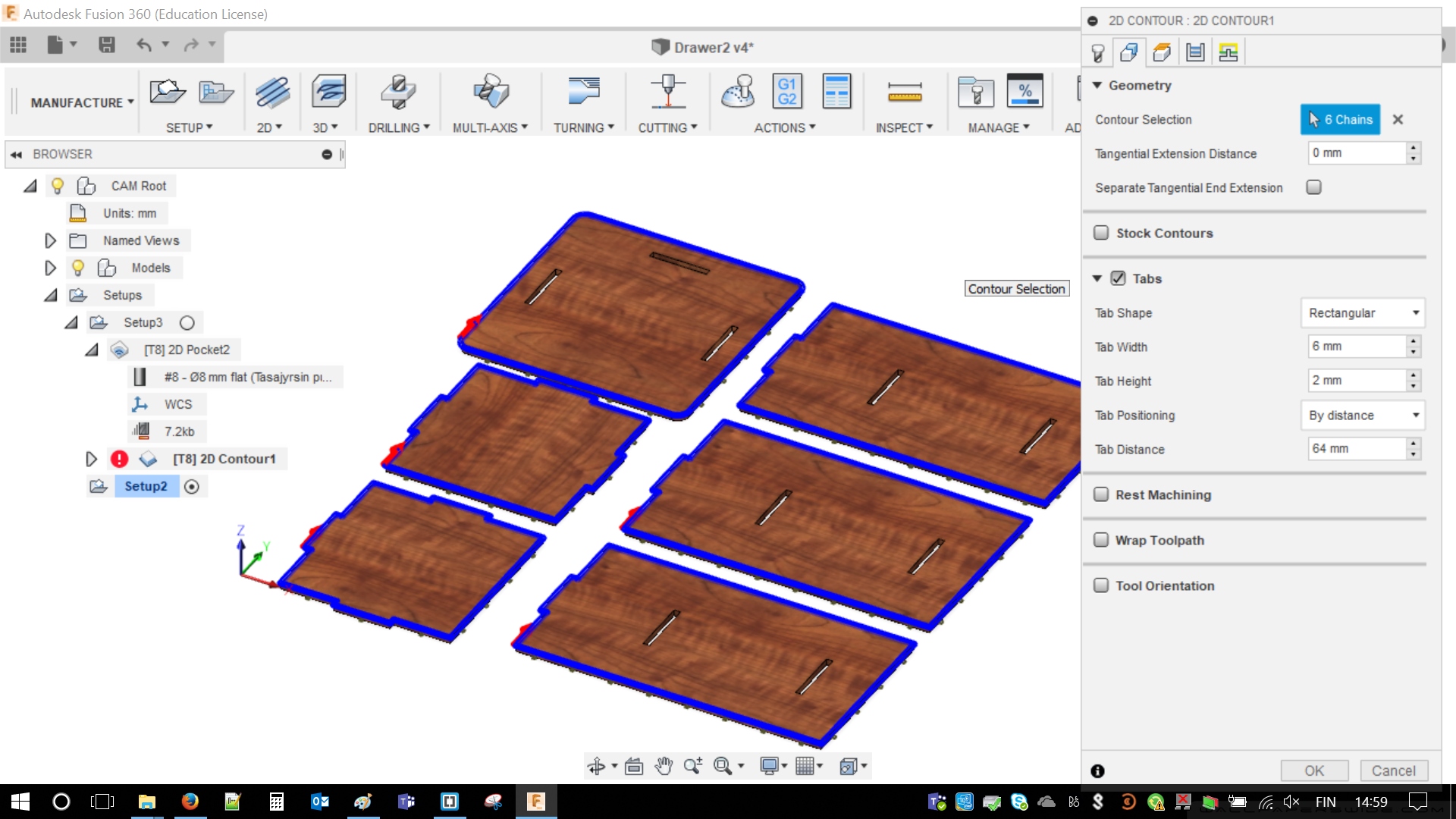
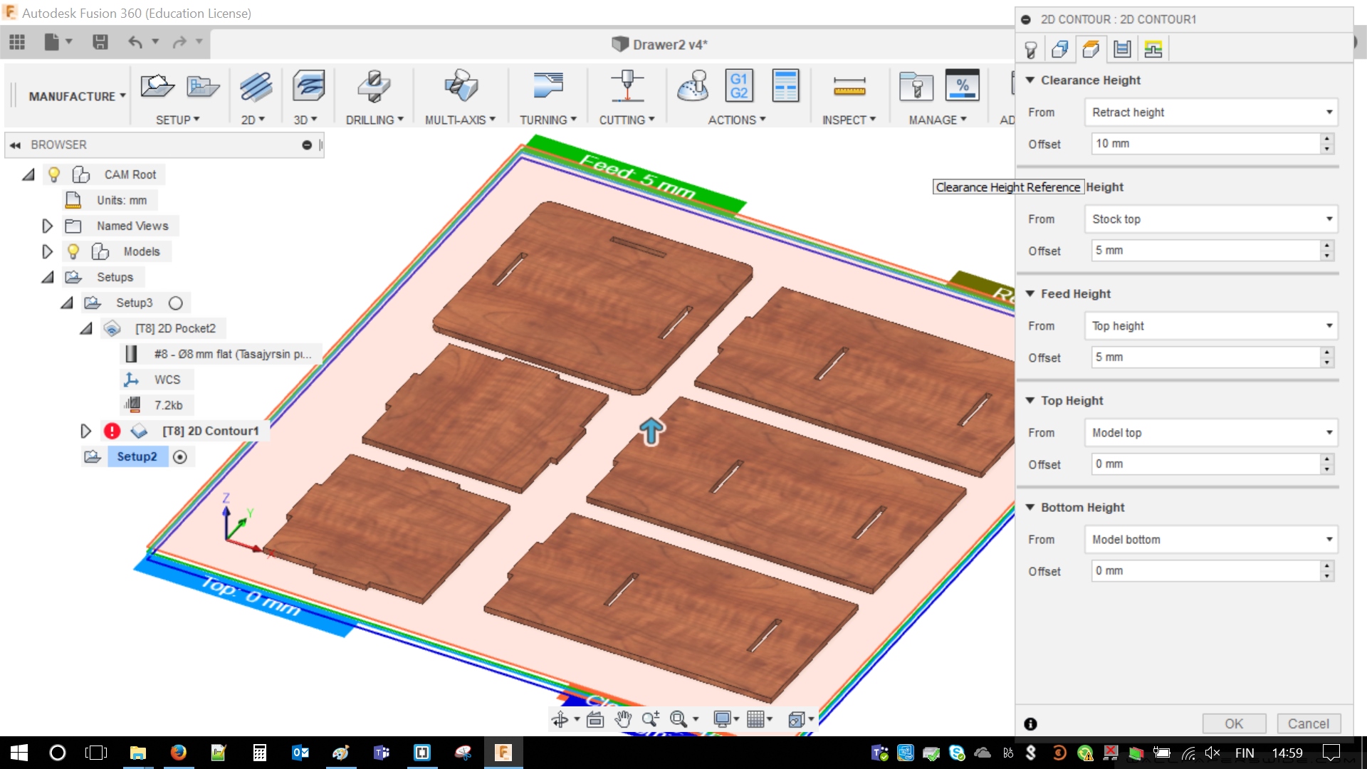
Heights, this time a bit less options. Values are: 10 mm / 5 mm / 5 mm / 0 mm / 0 mm. Names of the values are on the below image.
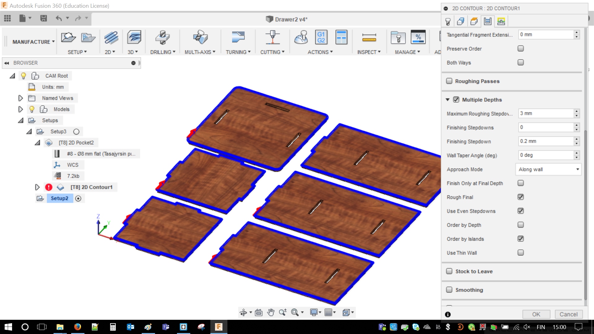
In passes I also used 3 mm step-down with even values. Order by islands.
There is not much to do in Linking. After double checking everything it is just necessary to confirm everything with OK.
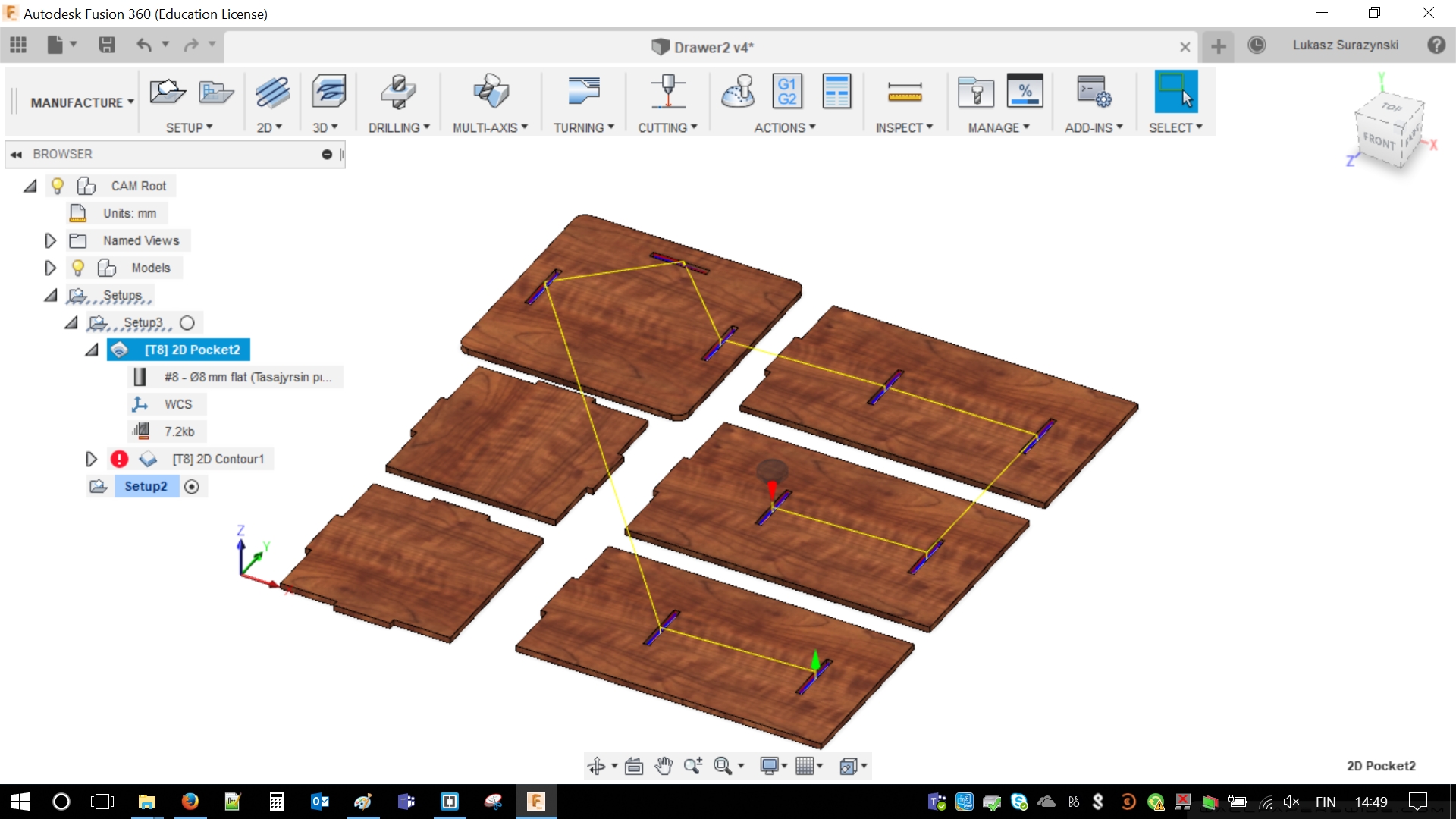
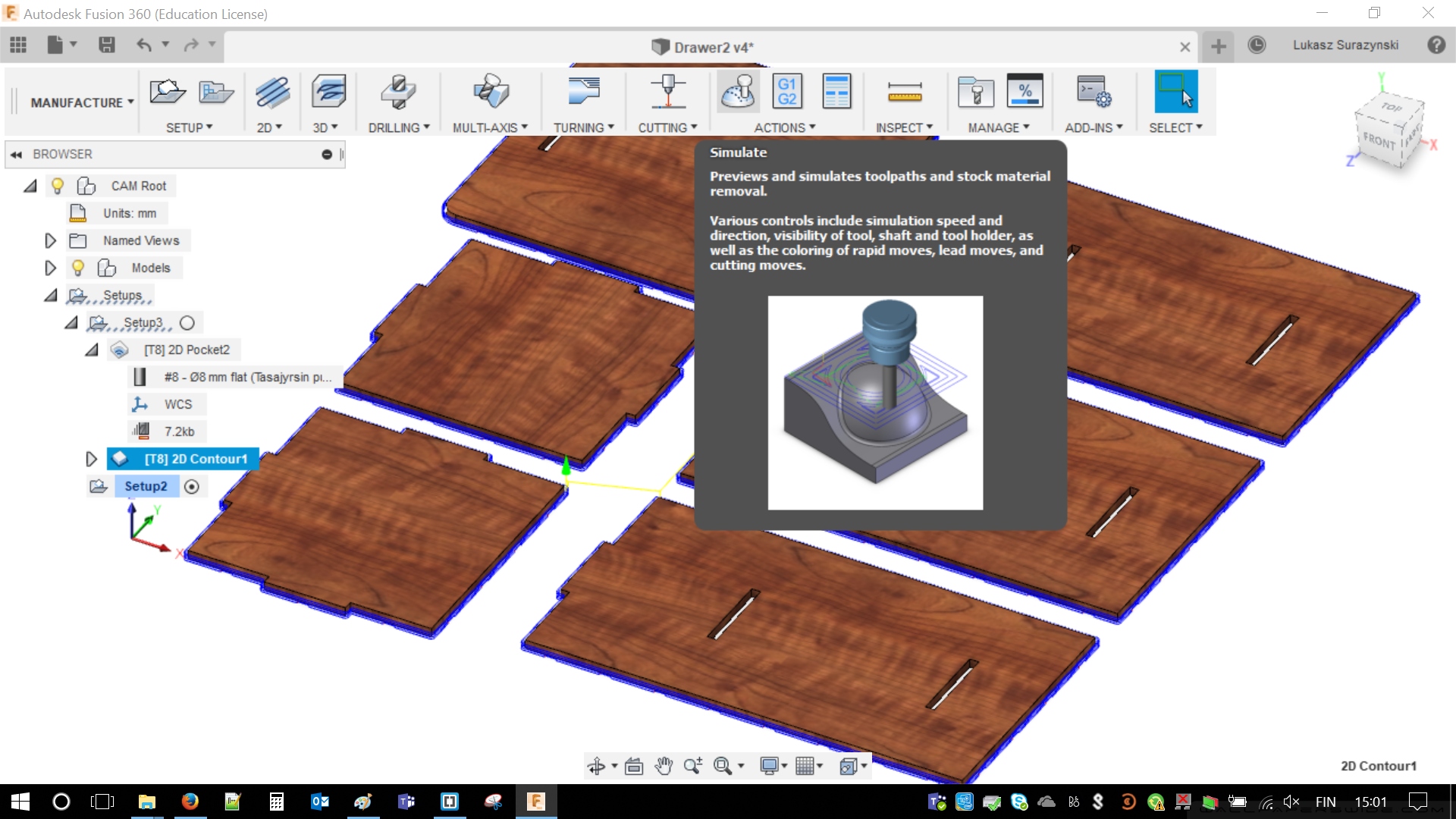
Some basic visualization of milling bit movement order will be shown. It is simple and informative. Nevertheless, some more interesting things are coming soon.
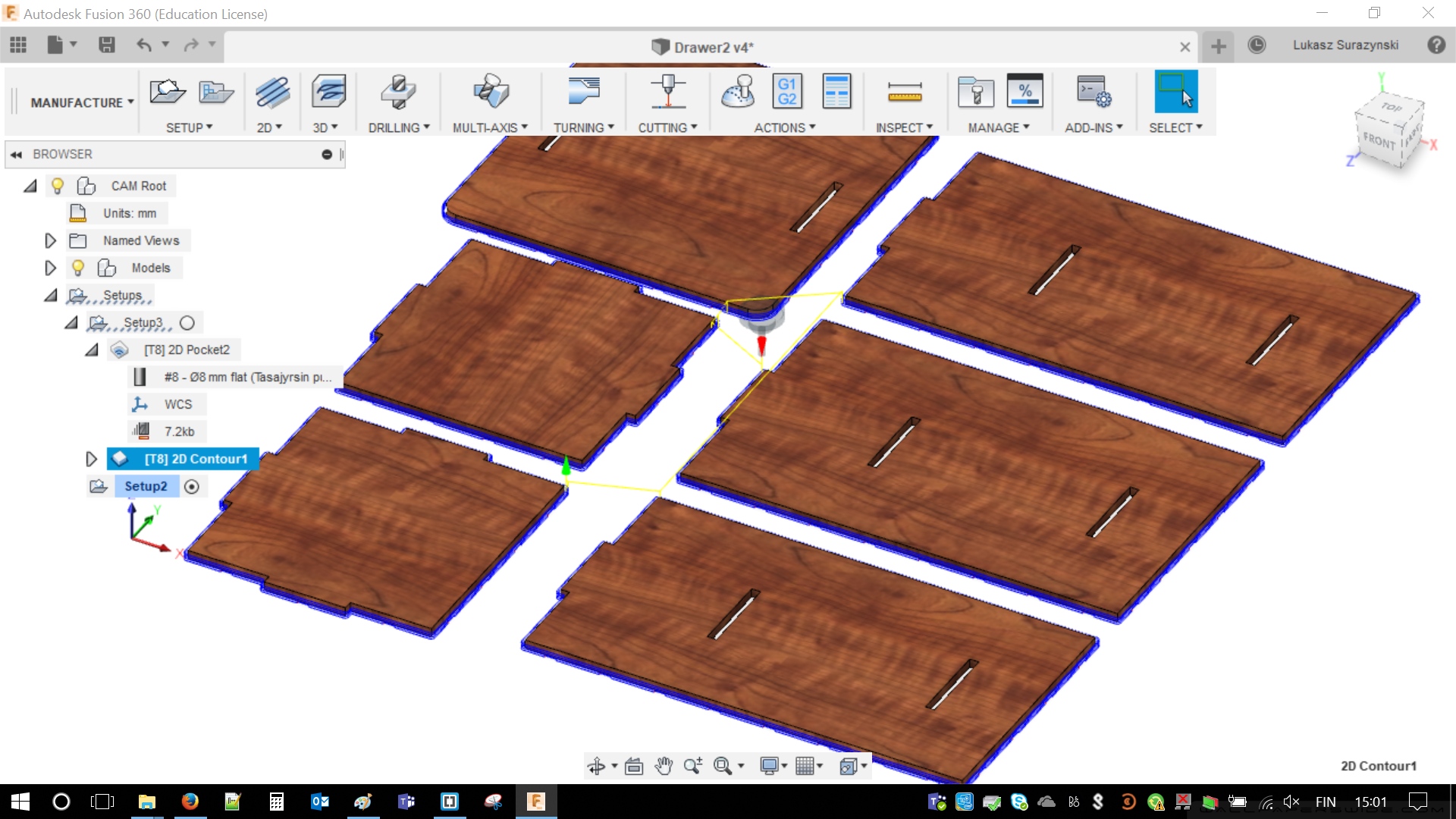
After adjusting pockets and contours it is possible to simulate milling. For that purpose I used build in function of Fusion - Actions/Simulate, afterwards it is possible to simulate milling on real milling machine. There is never enough of simulations.
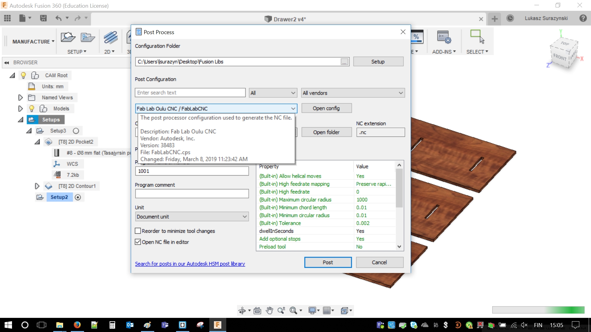
I liked results of my simulation. I decided to create .NC milling file for my drawer. This was final step in designing software. The rest was almost purely practical.
Milling
I successfully uploaded my files onto CNC miller. I even made a simulation in order to check if milling bit did not skipped any part. Everything was correct. Then I simply followed instructions given during team assignment. Below I archived the process with photos and screenshots.
 |
 |
Everything stared with power buttons. I turned on vacuum pump and pushed main power button. Main fuse was already on as some people worked in the room already. If machine does not turn on, usually it is cause by turned off main fuse.
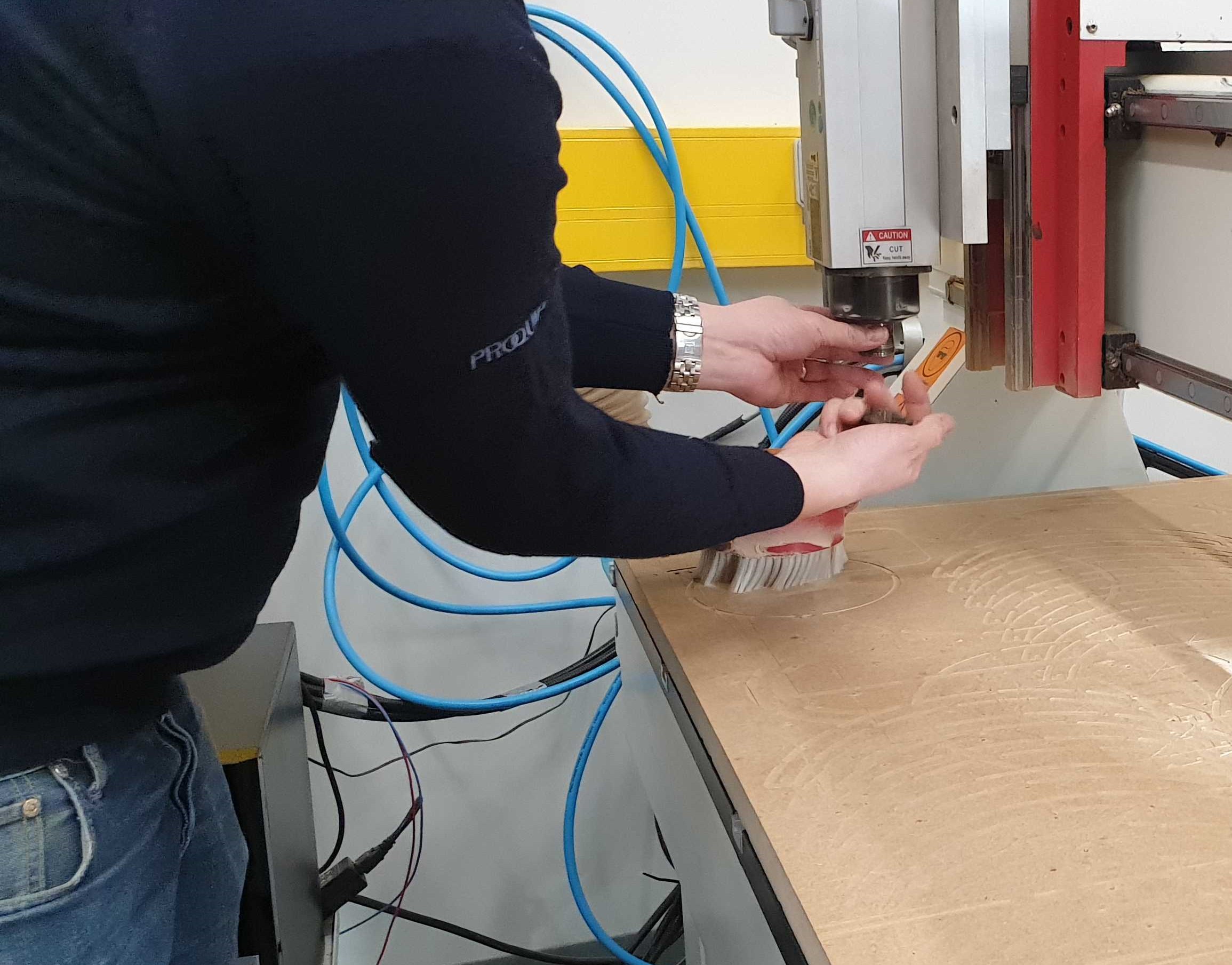
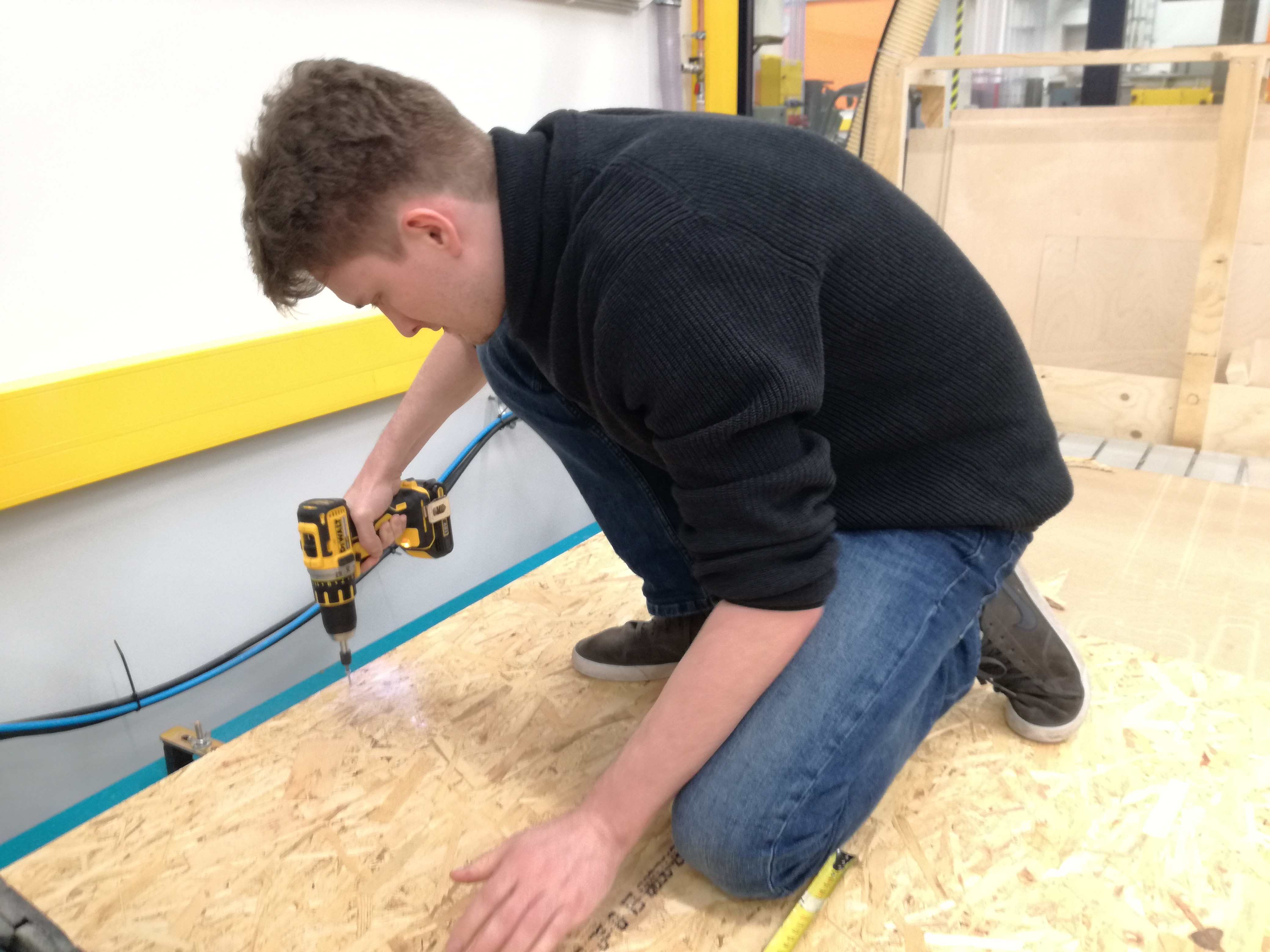
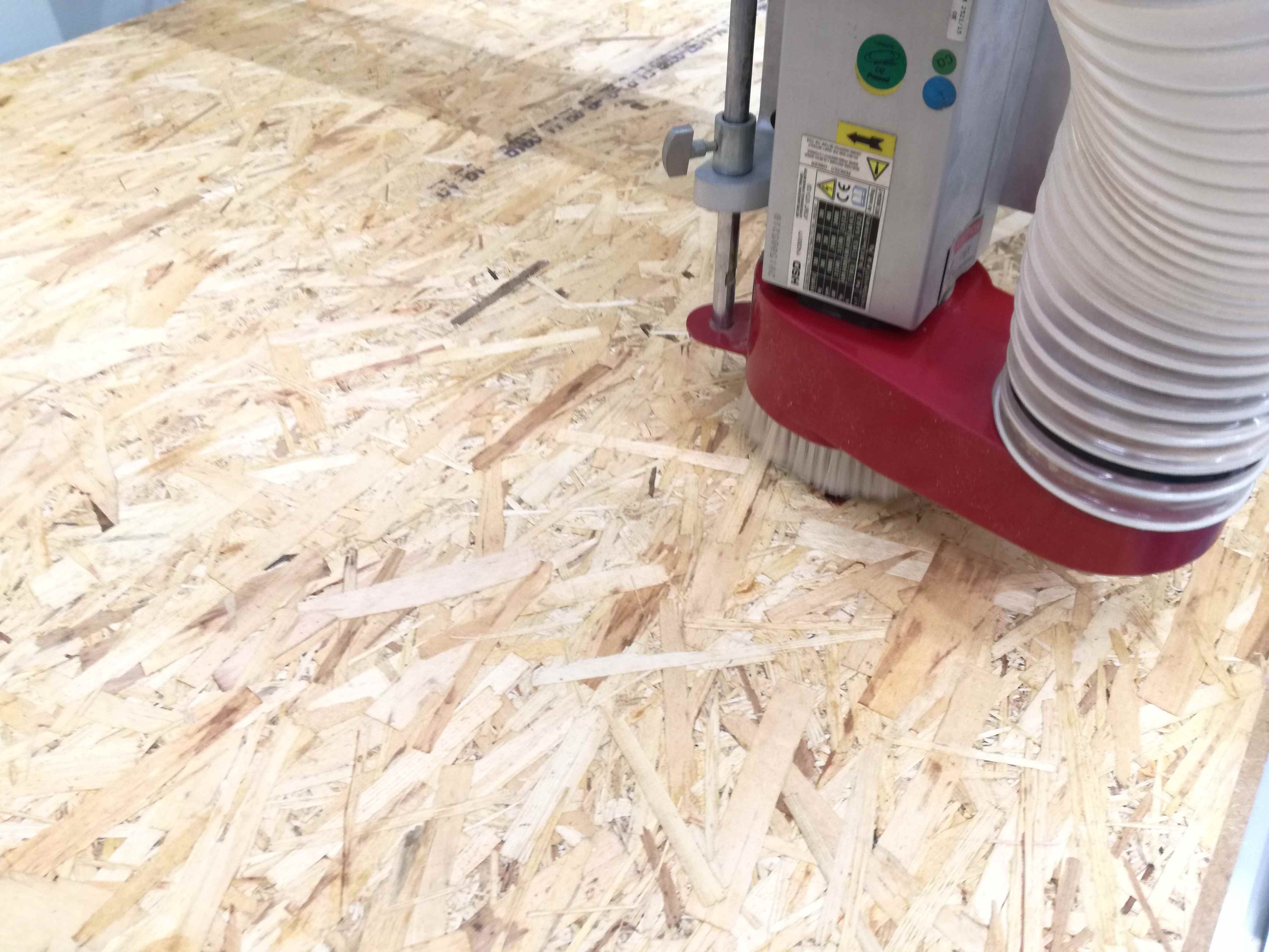
I followed instructions from group work (those can be find at the top of this page). First of all I zeroed axes using pilot and dedicated button on the software menu. I decided I will manage without automated zeroing of Z axis. Future shown that I did it correctly. It was a smart way (I guess every other student's approach). I turned on the rotation of the milling bit and moved spindle as close as possible until I heard scratching on the surface. I set my beginning point to fit all elements, which was top left corner of my material (It depends on alignment of parts, done in Fusion).
As I used standard, flat 8 mm milling bit so I decided to use all standard values of feeds as well. Those were already set in Fusion, simply didn't touch them in NC Studio. However, I played with rotation speed, it was set to 80% as I've heard this material does not require full speed of rotation. With full speed sometimes it is not milling but rather burning the material (squeaky sounds). As the simulation went right I wasn't expecting any errors. I just pressed "START" button and observed.
 |
 |
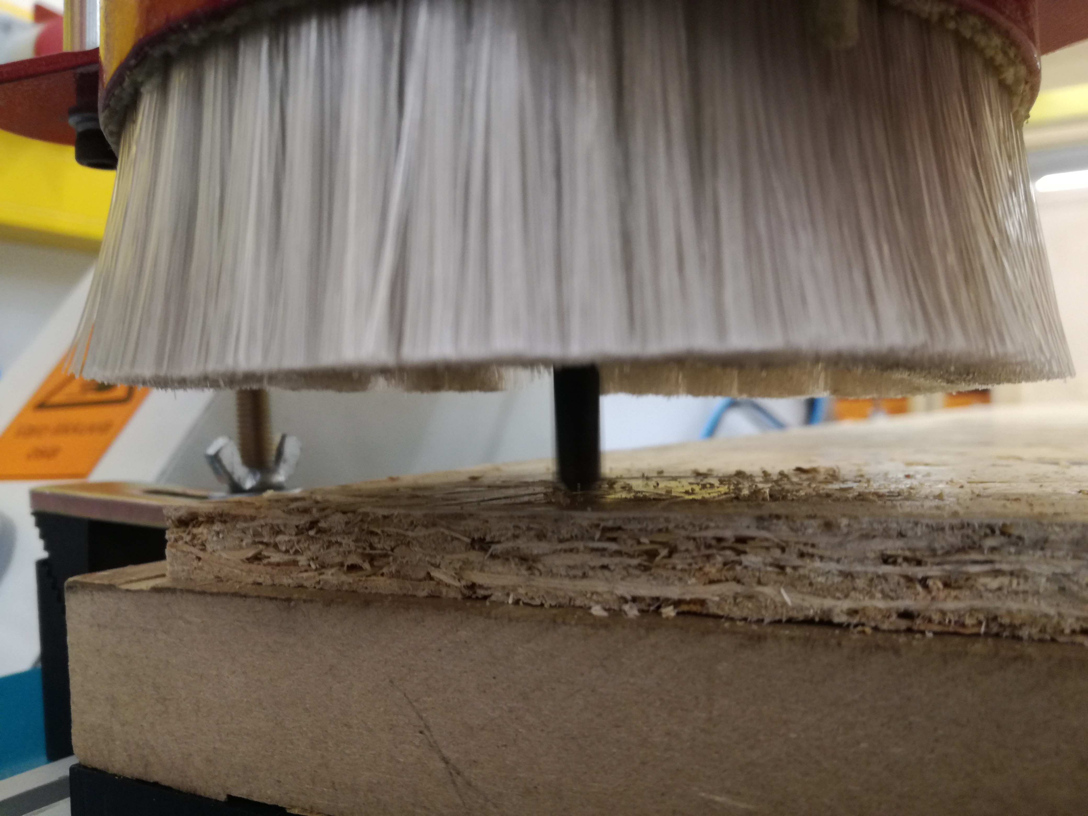 |
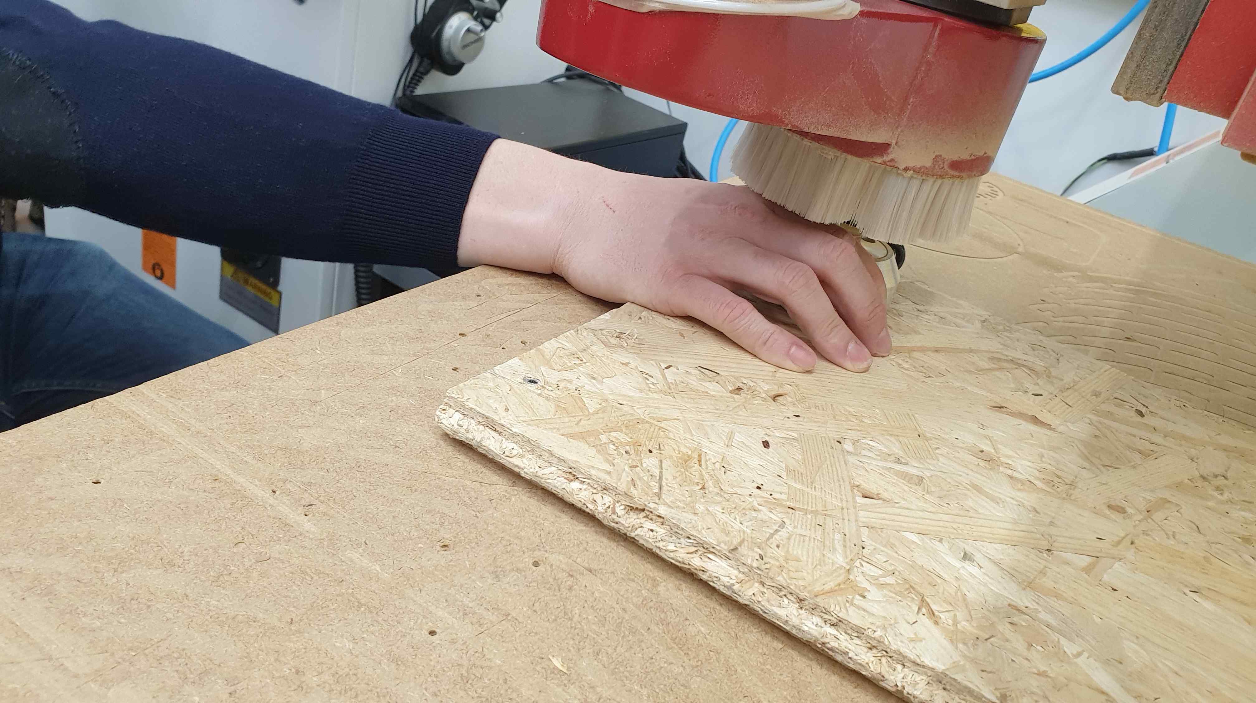
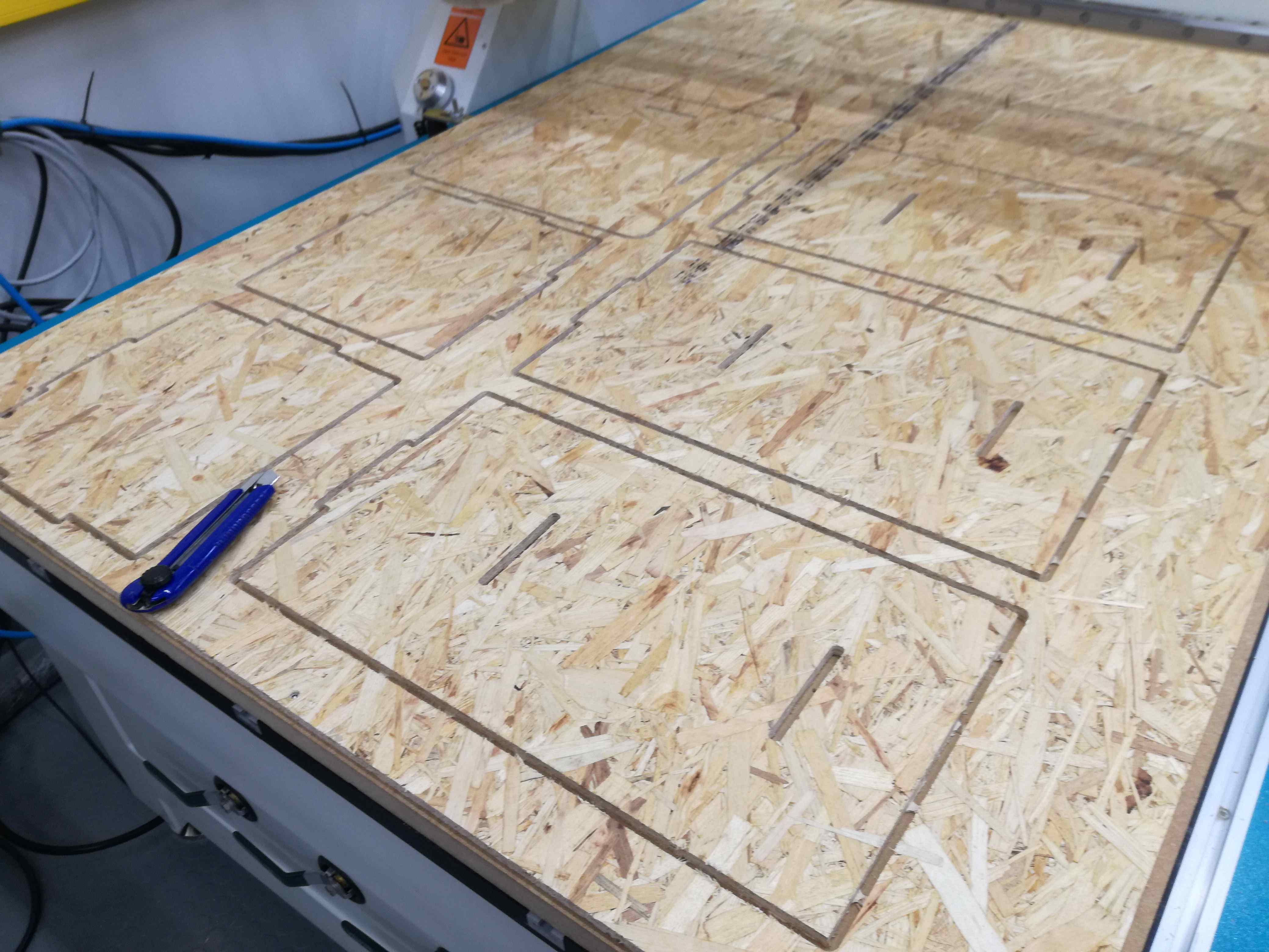
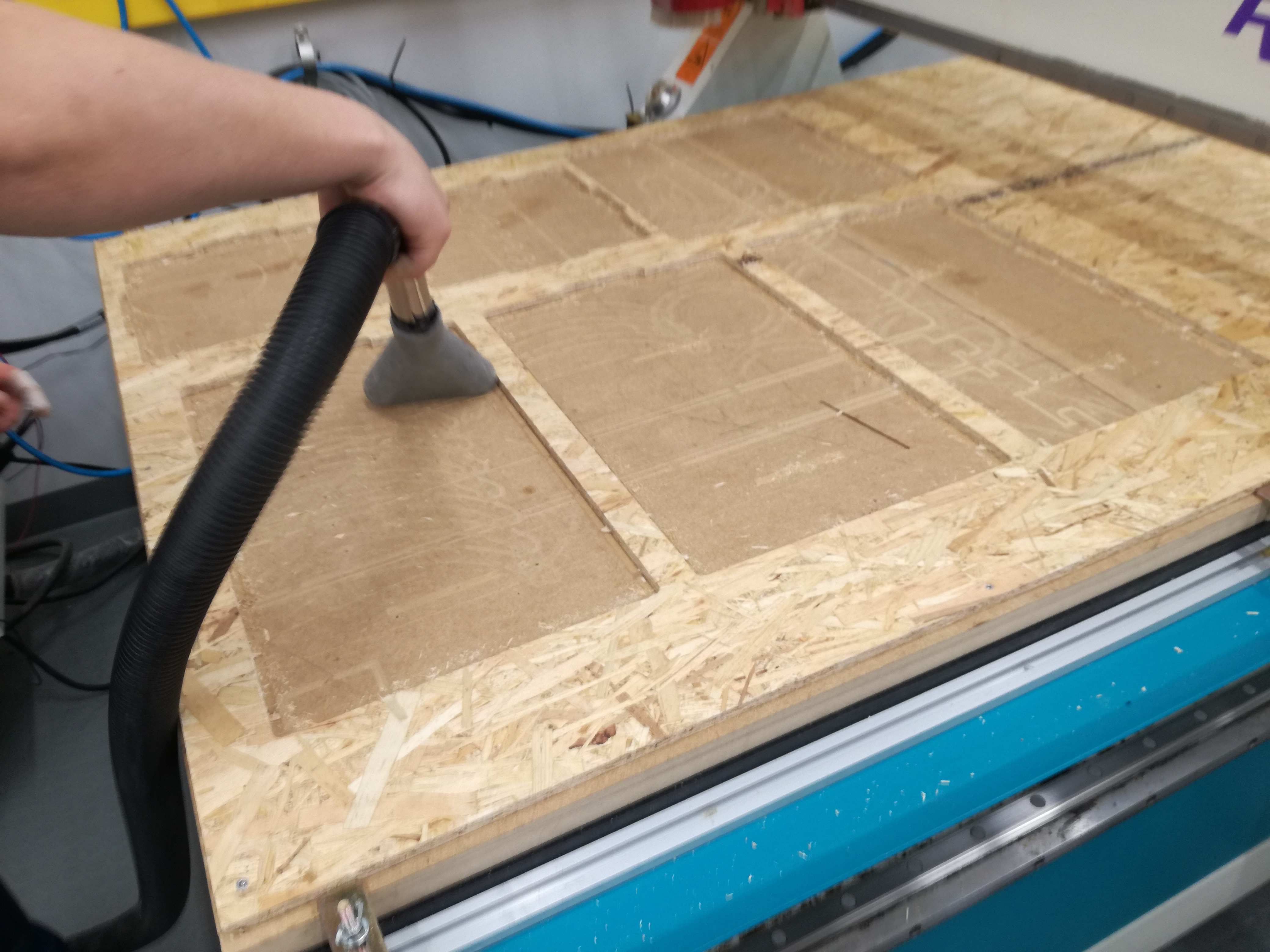
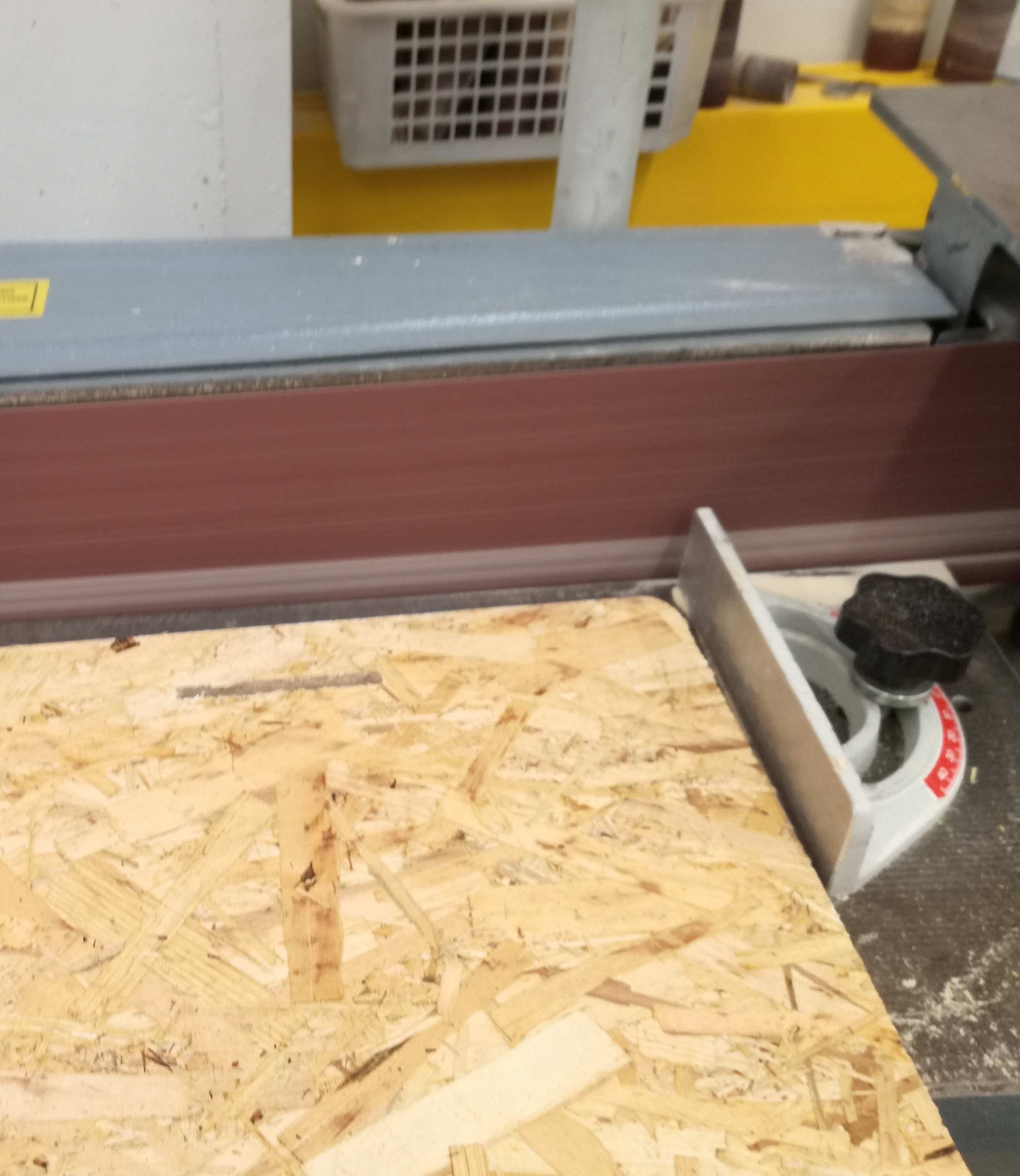
Material was full of thorns, it pushed me to make some polishing. Moreover, it is not even in therms of thickness (with some reasonable tolerance) so I had to work a bit on the side holes using file and paper knife. Nothing difficult or requiring a lot of strength. In the end a bit of hammering to squeeze the parts together was required and drawer was finally ready.
 |
 |
 |
 |
 |
 |
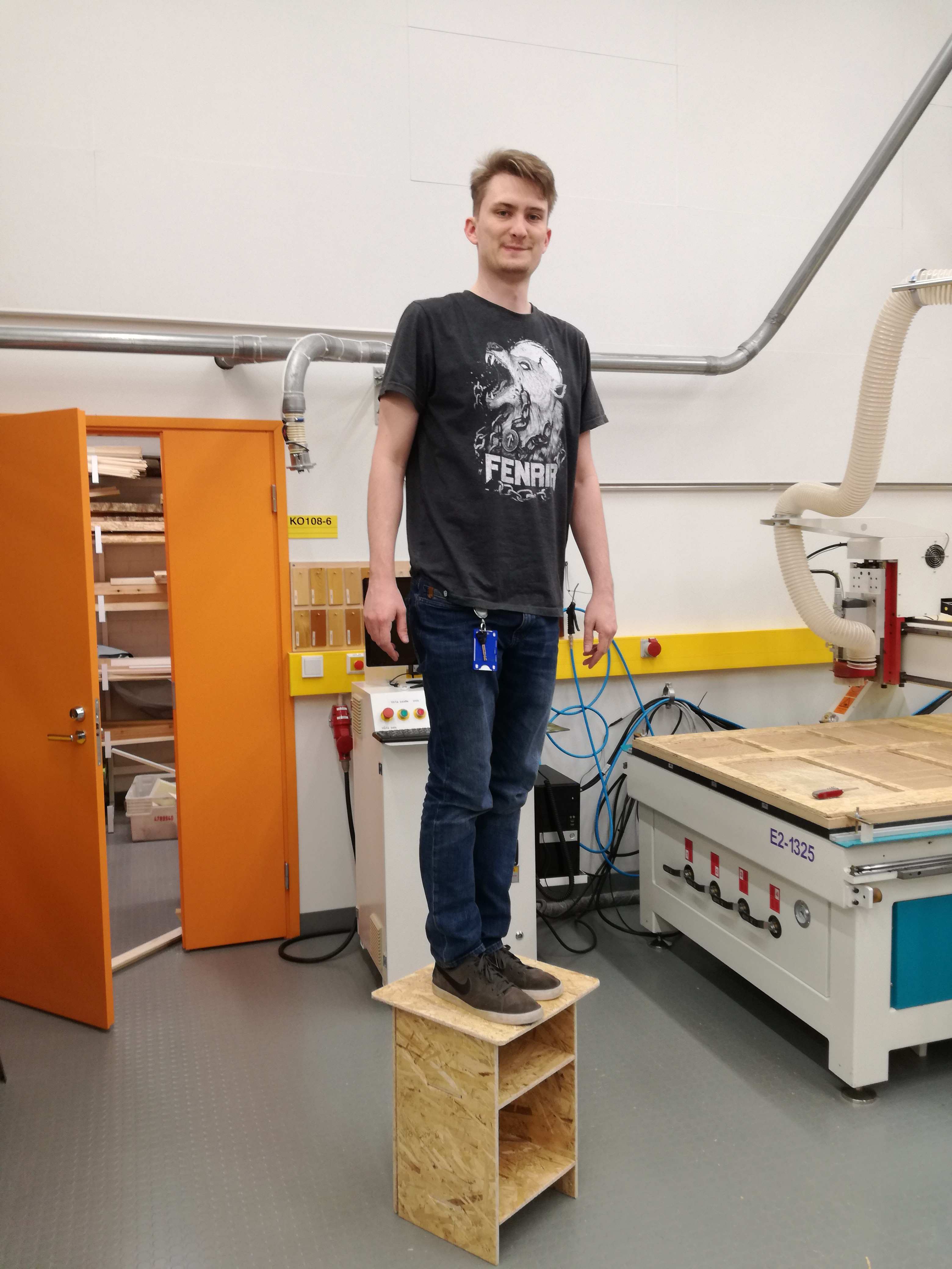
According to my knowledge about engineering history I decided for some special testing. If engineer designed a bridge, he shall stay under it during tests. This is me on my drawer. No animals or humans get harmed.