Week 11: Input devices
Input devices are opposite to output devices. Still most likely you need both because if there is no reaction on given stimulus most likely system doesn't make any sense. This is quite short introduction this week.
Group Assignment
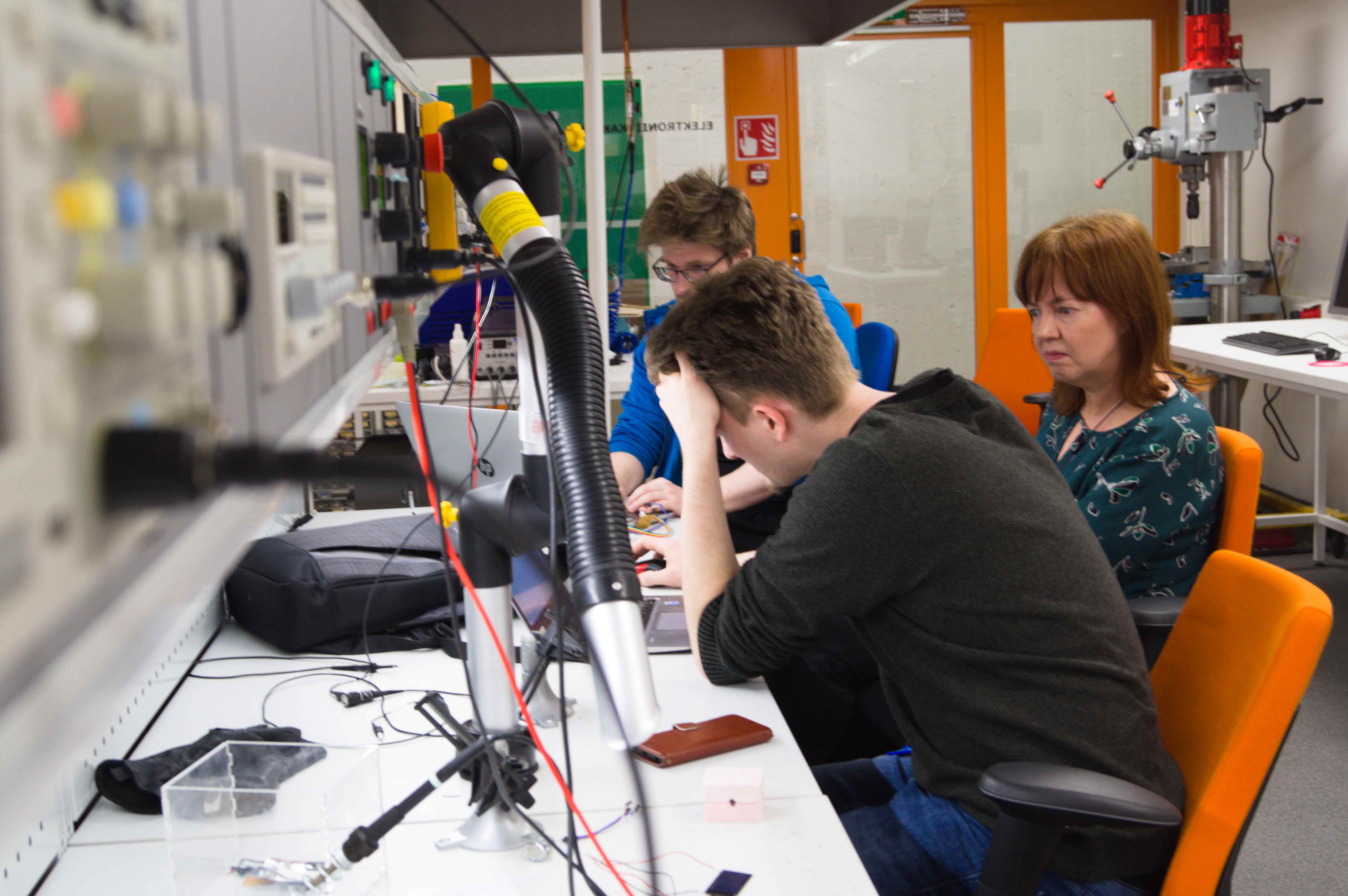
Members: Gleb, Marjo, Perttu and me
Probe an input device's analog levels and digital signals.
Photovoltaics
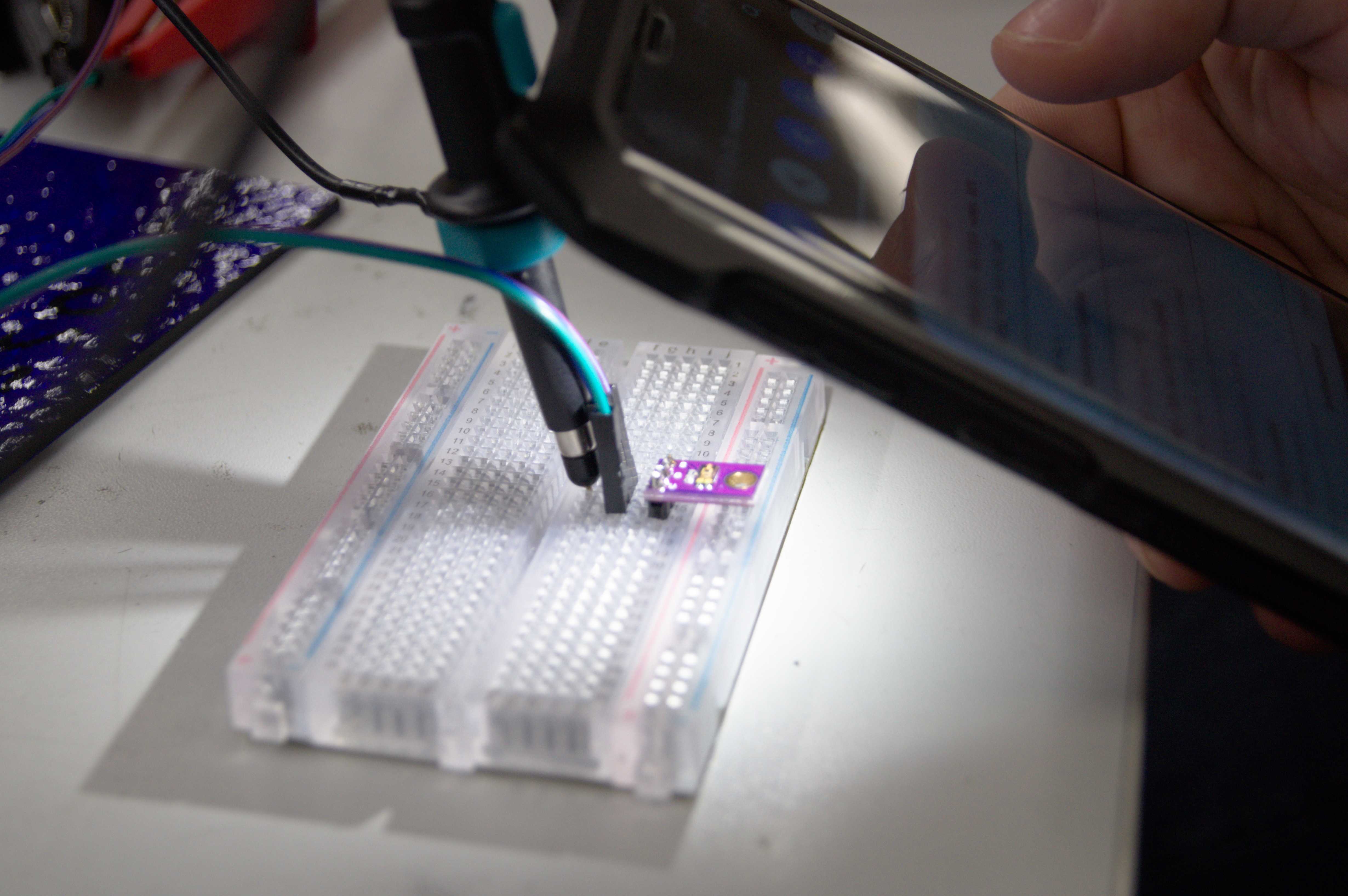
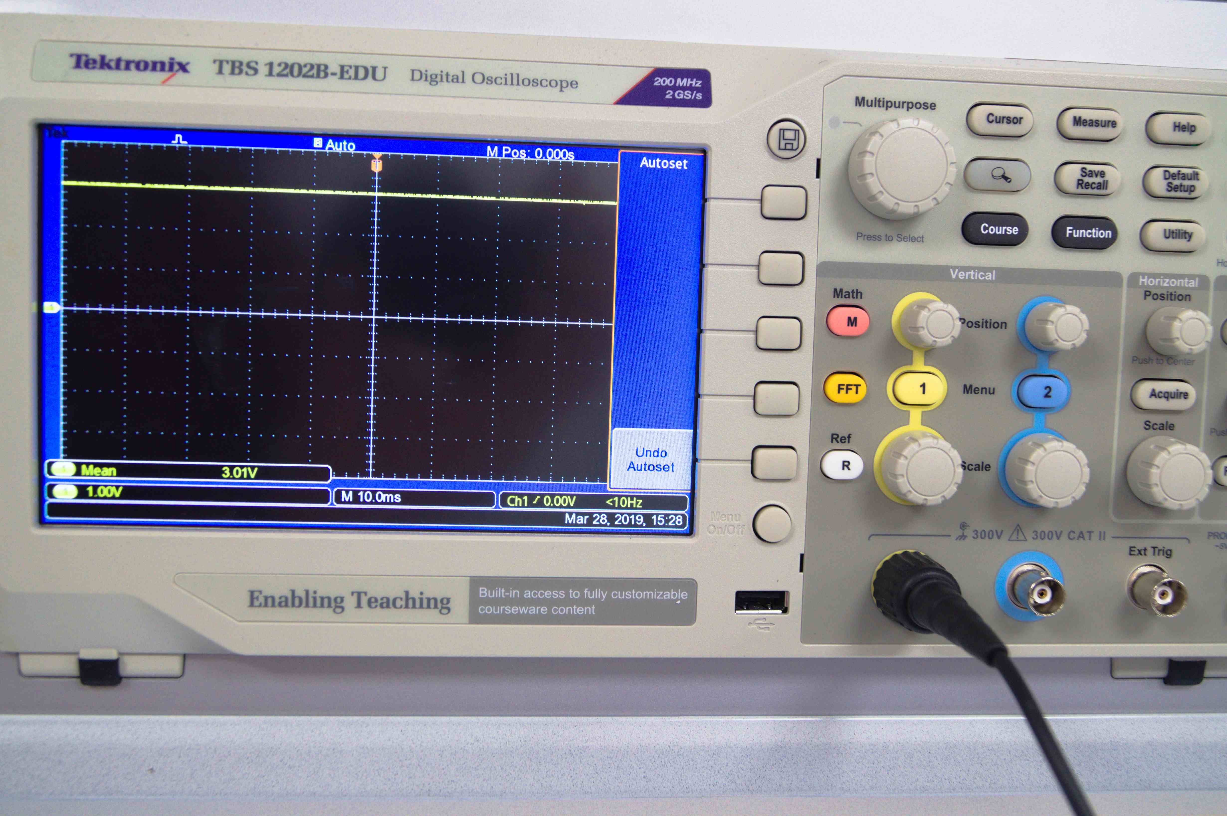
We decided to start with measuring signals from analog input devices. We have found couple photovoltaic modules. Those were rather small size compared to solar panels, which might be found on the roof. Nevertheless, we managed to obtain some decent voltage levels. We tried the differences between fluorescent lamp and Smartphone LED.
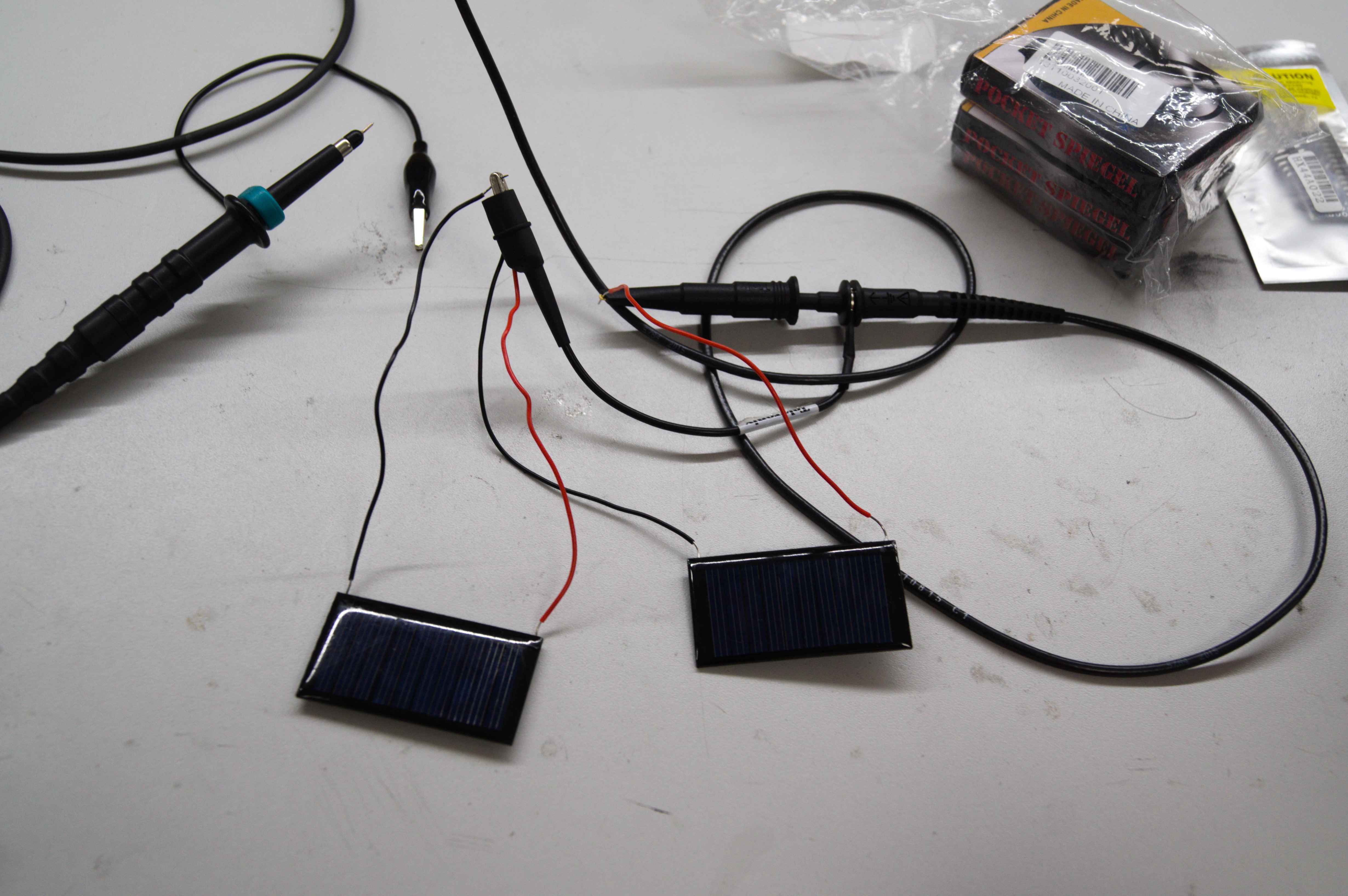
Our test units were connected in series in order to obtain higher voltage values. We were using oscilloscope to measure output. We could have used multimeter with the same success.
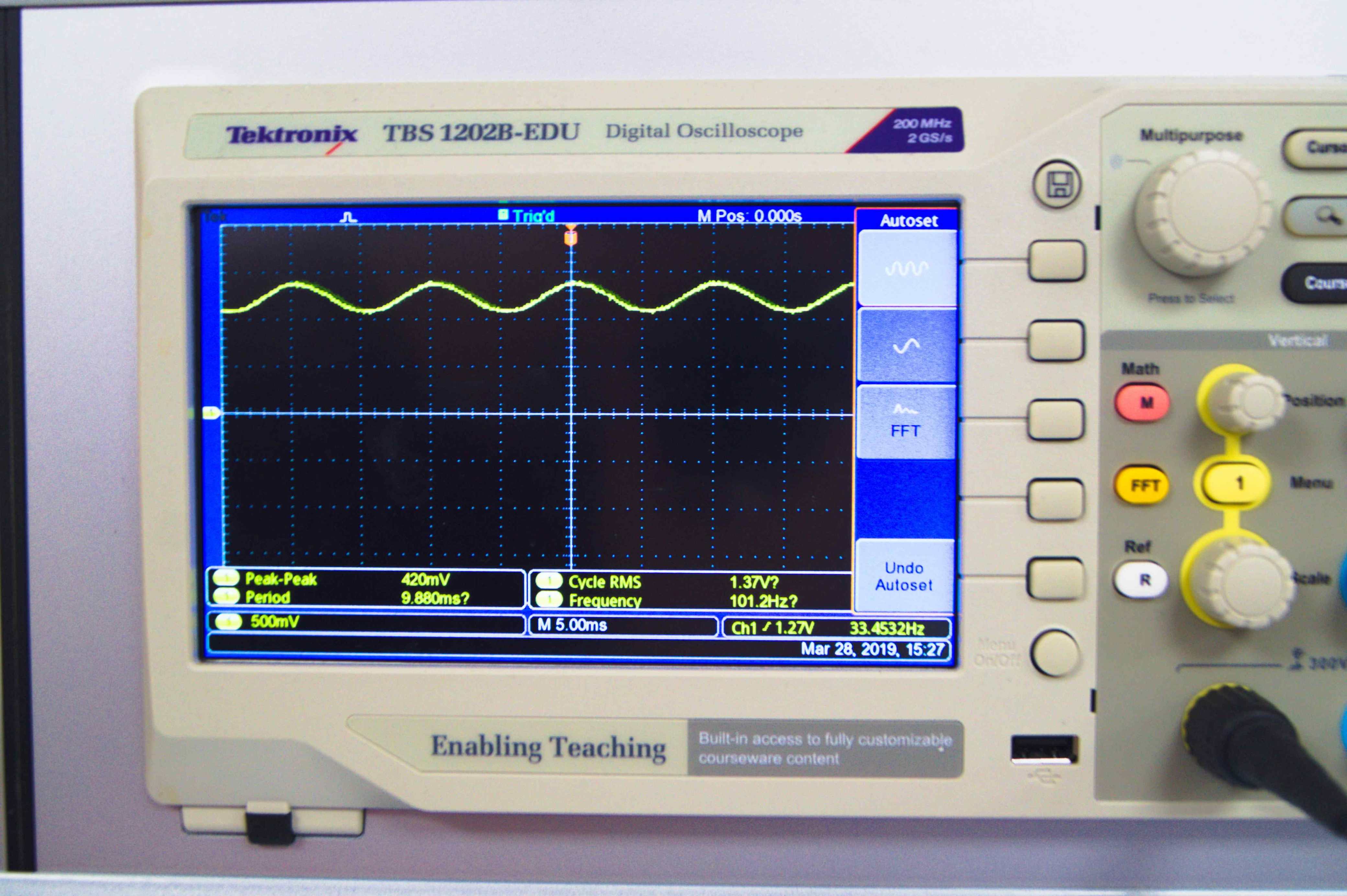
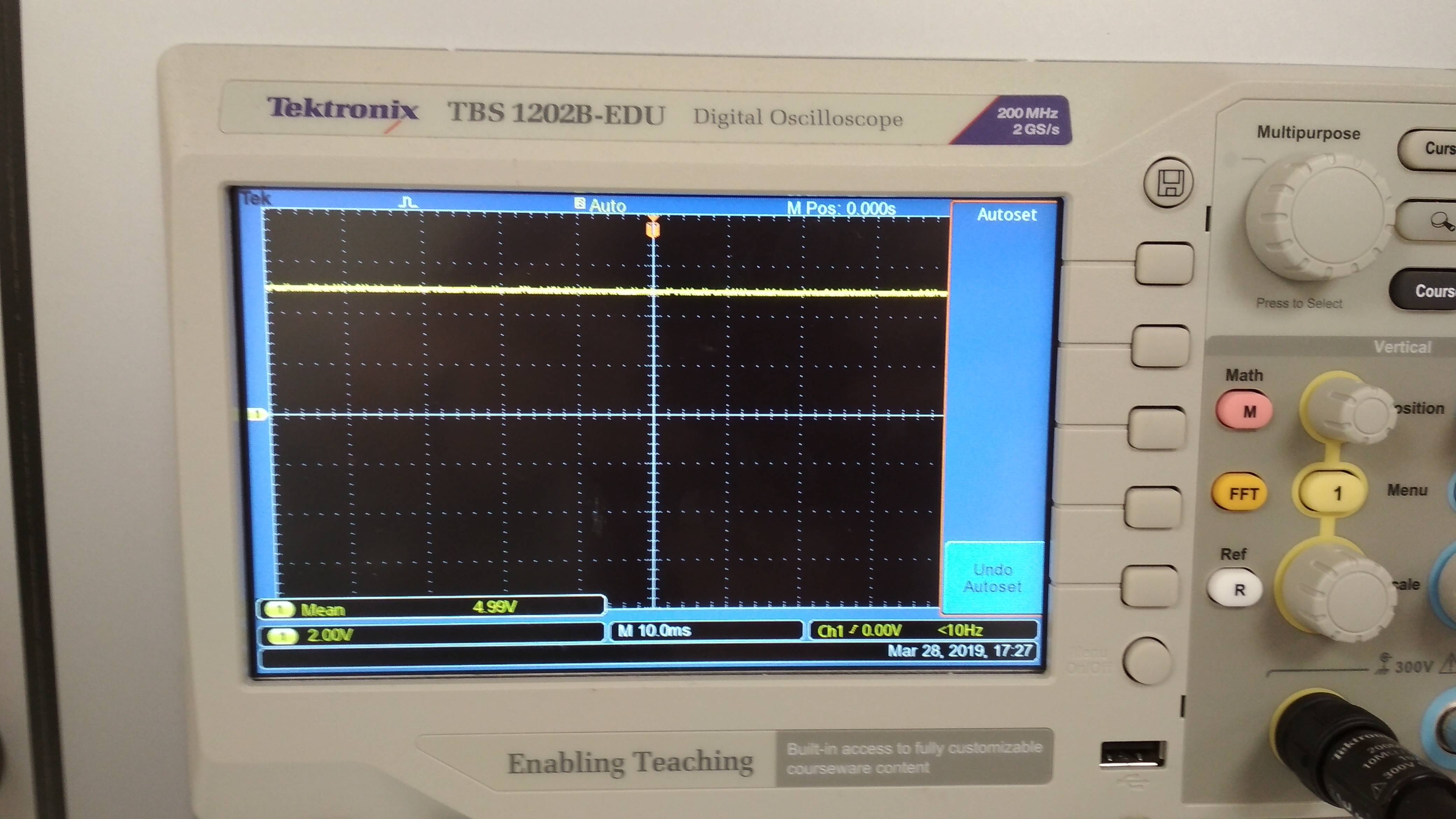
Differences are easily visible. LED provided stable voltage level, where lamp was fluctuating with 50 Hz frequency.
Photoresistor and LED
We managed this part quite well. We decided to work with ATTiny from now on. We have found photoresistor, element, which changes its resistance in presence of light. Our unit was nice, already embedded on the PCB. Circuit was simple - voltage divider. Value of first resistor is fixed, where photoresistor resistance varies. Voltage across photoresistor will change depending on light strength. There are three pins, which needs to be connected. Power line (TTL logic values), ground and signal pin - output value.
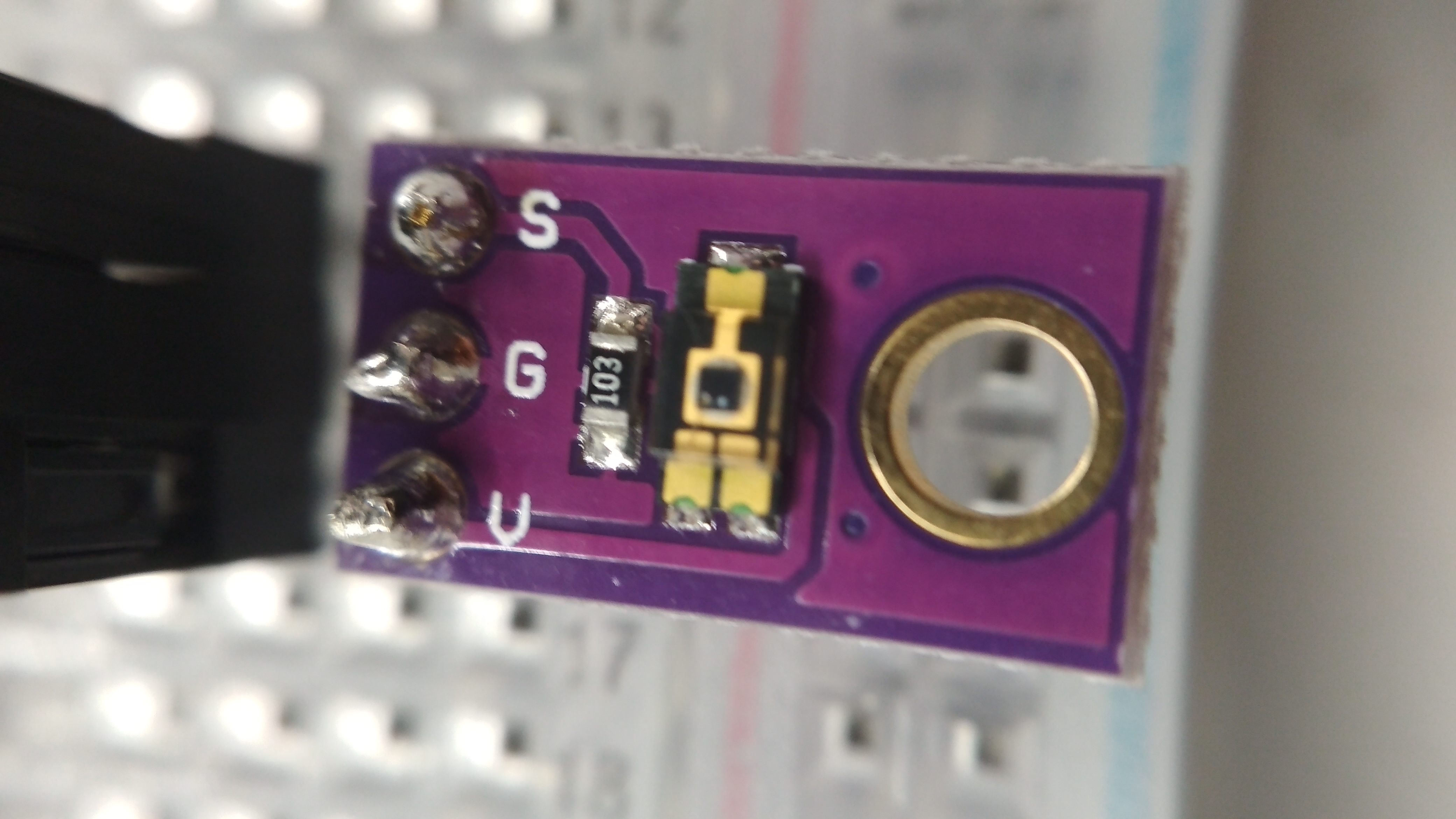
Just to be sure that our device is working properly, we have checked values using oscilloscope. Circuit was powered from USB port. Everything worked as expected.
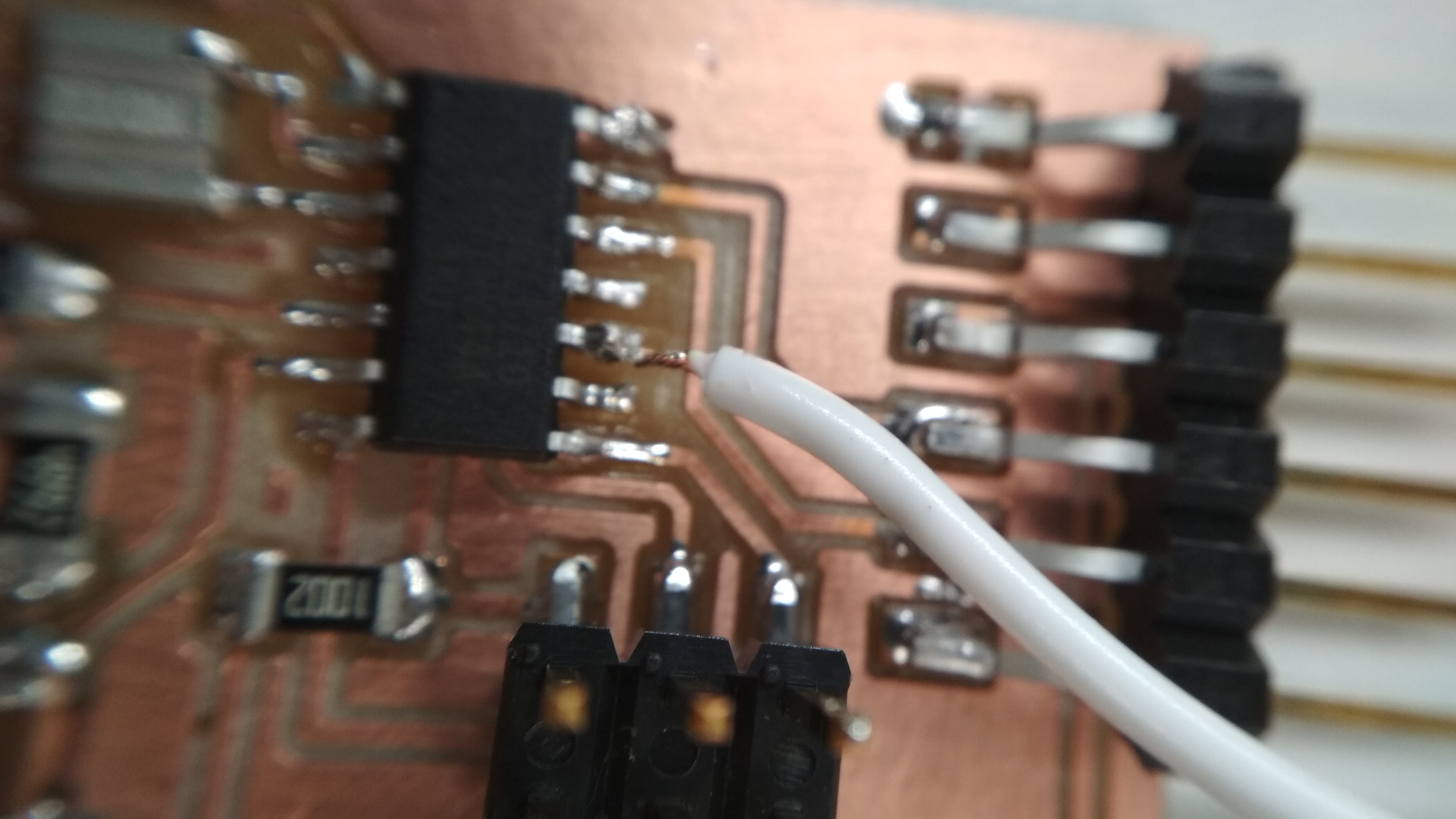
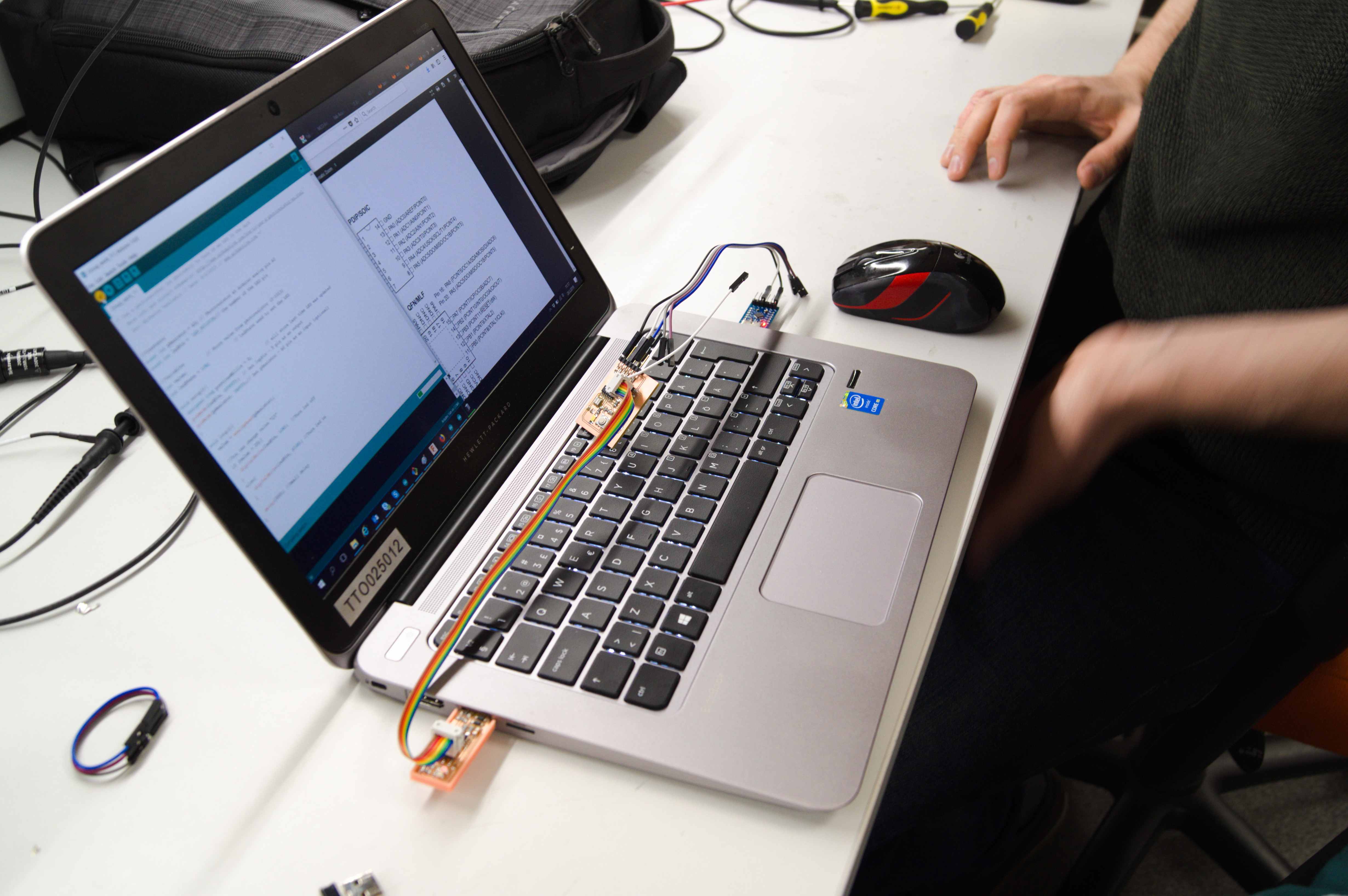
As said before our plan was to use ATTiny. Using Arduino IDE, we create a code, which was turning LED on every time photoresistor was lacking light. Our previously designed board didn't have pinheads to connect with output boards, because of that we simply soldered signal line to unused port.
Programming was interesting, as unluckily laptop, which we were using had very limited amounts of USB ports. Regards to Hewlett-Packard. Anyway, we managed and we continued our journey.
.
After programming circuit was supplied from USB port. It didn't require more than two connections, 5V and GND. After couple attempts we managed to make it fully functional. It could be used as demonstration setup as working principle is similar to lamps with dusk sensor. Below some a little proof that it worked.
Photoresistor and Serial port
Alright, analog input to analog output worked nicely. Finally, we decided to test analog to digital version. For this instance, ATTiny will send some characters depending on what it will sense with previously used photoresistor. This time connection was a bit more complicated.
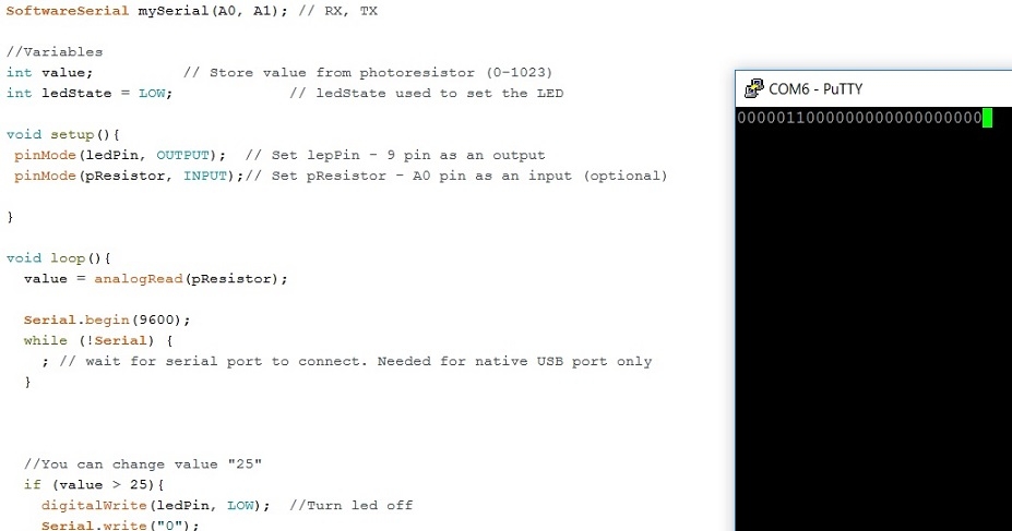
We have improved Arduino code, every time there will be no light detected "0" will be send, where any voltage (create by light) above given threshold will send "1" over serial port. This would be easily readable using putty. After couple attempts we achieved it.
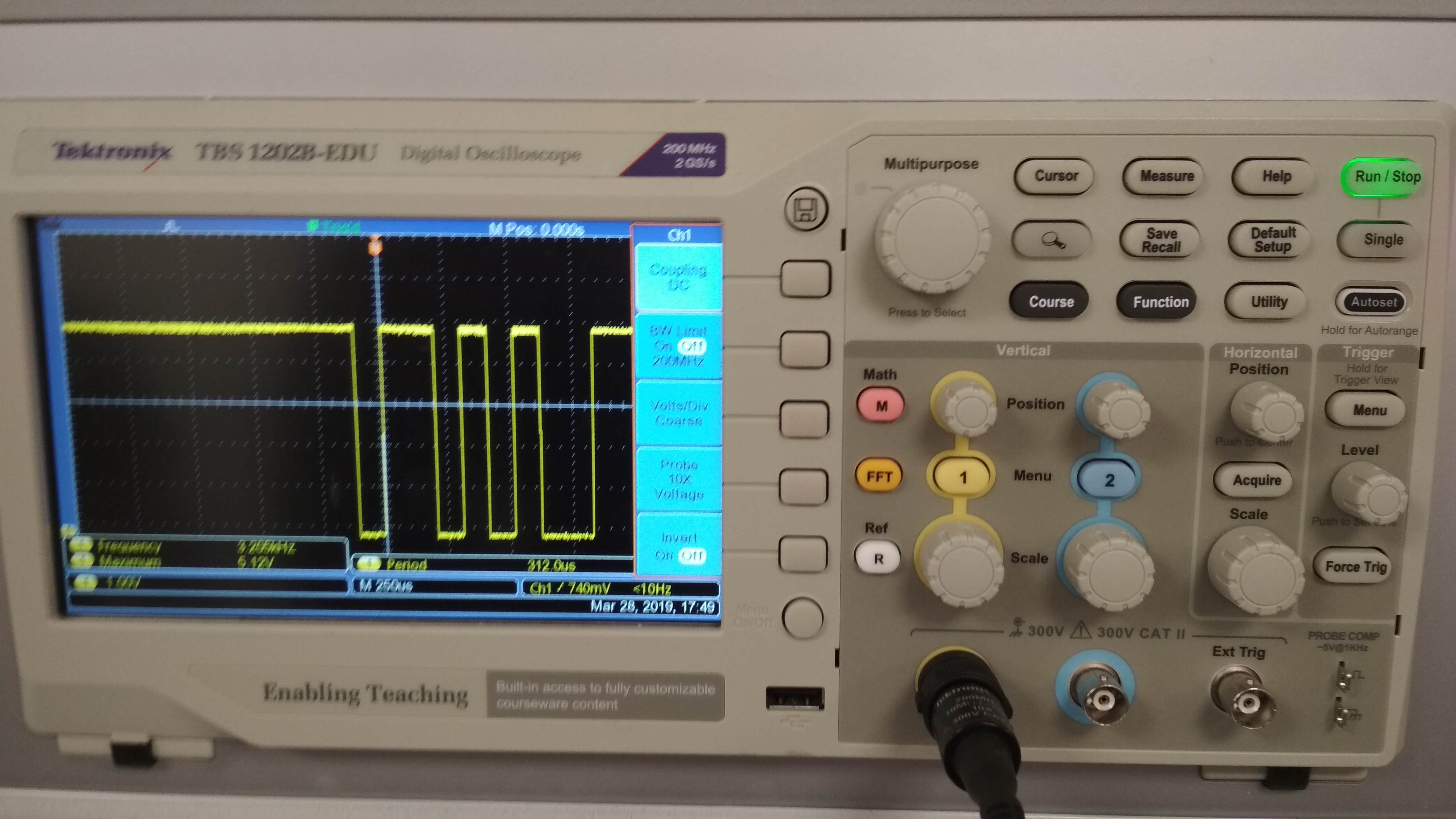
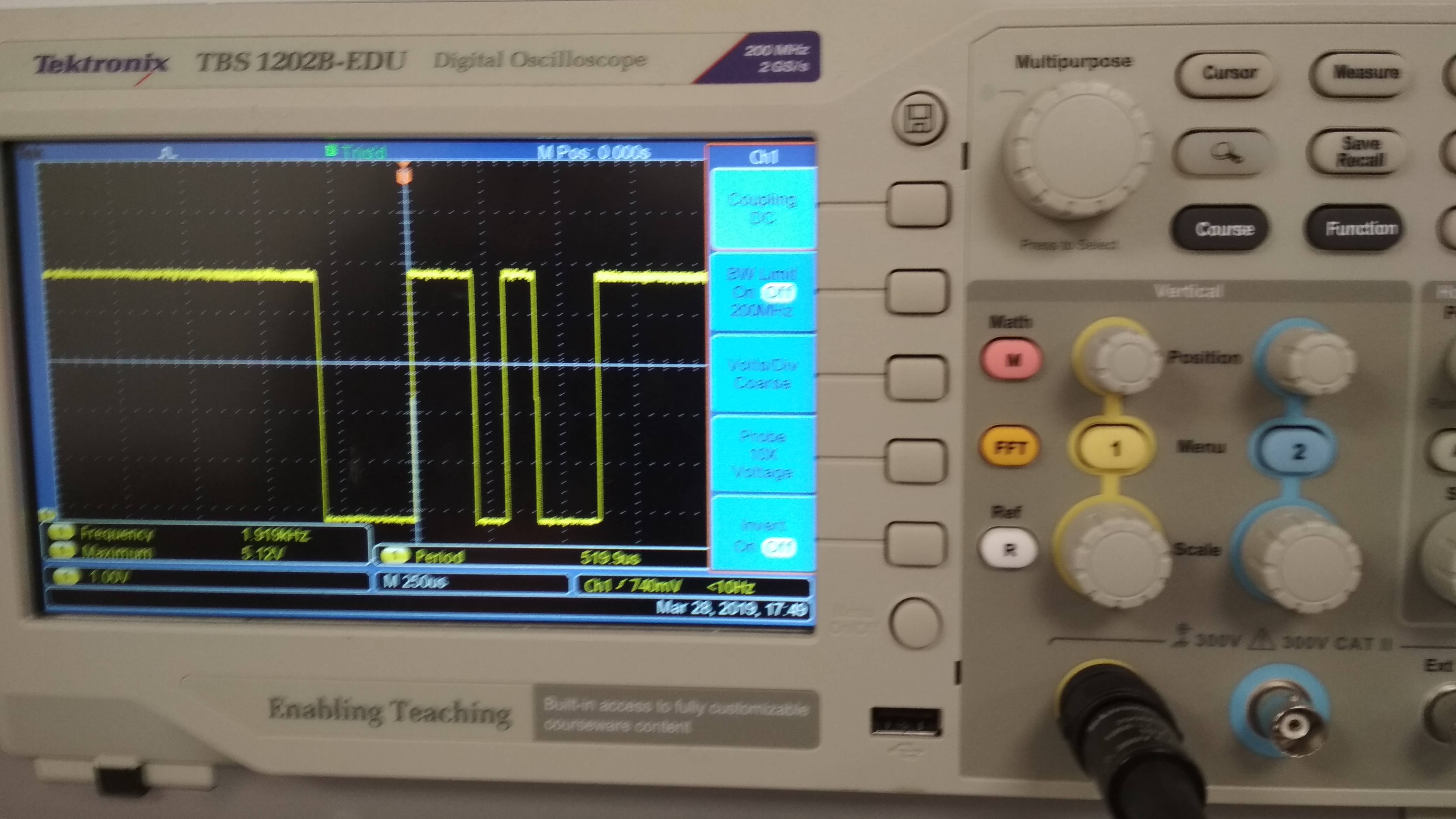
After a moment we decided to investigate Arduino function Serial.Wire and instead using characters, we used ASCII codes. We picked two random numbers: "43" and "44". It turned out that first was plus sign and second was comma. Fair enough. We measured transmission using oscilloscope. Everything worked well.
Both Arduino codes are available to download in correct section. There are very descriptive comments on each functionality
Individual Assignment
Creating schematic
Measure something: add a sensor to a microcontroller board that you have designed and read it.
I had very late start this week. I hope everything, which is good starts with some kind of disaster. This time disaster was ripping of my ISP pins out of the board. The valuable lesson from life is: in Winter there is ice, ice is slippery, when you slide without control - you are trying to grip to something, despite of having PCBs in your hands.
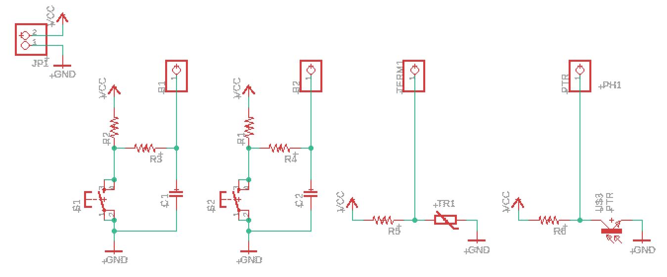
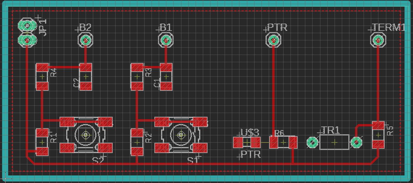
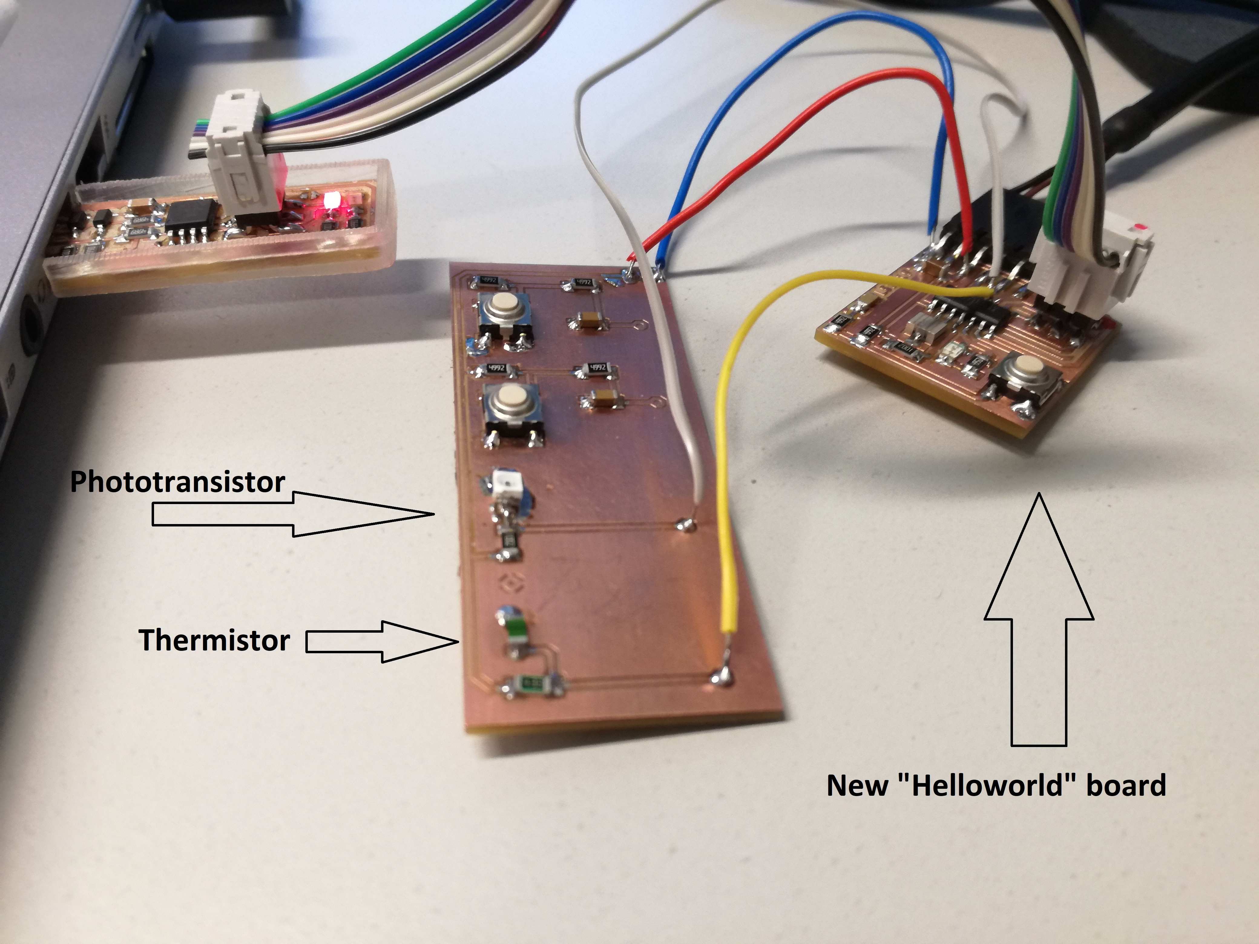
So I went trough part of Electronics design week and fabricated another "Hello world board". In the meantime I designed something that I call "Interface". It includes:
- Two buttons with debouncer circuits
- Phototransistor circuit
- Thermistor circuit
- Power supply pins
My intention was to use it for the final project as interface with the user. However, not everything went well as planned. I think I will create another interface board. Of course I will describe this with more details on Final project page. I set size of the board to 7 x 3 [cm] in order to fit it in TARS case (currently dimensions are in my own head).
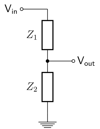
The good news is that I could use Interface board for purpose of this week assignment as well. Schematic is very simple. The only new feature is voltage divider configuration, in which both thermistor and phototransistor are working. Both elements are active and change their resistance under changes of illumination or temperature. It creates voltage drops on them, which may be sensed using microcontrollers ADC pins. In order to choose correct resistors I used datasheets for both active components. Those might be found under following links: Photoresistor and Thermistor.
Printed circuit board
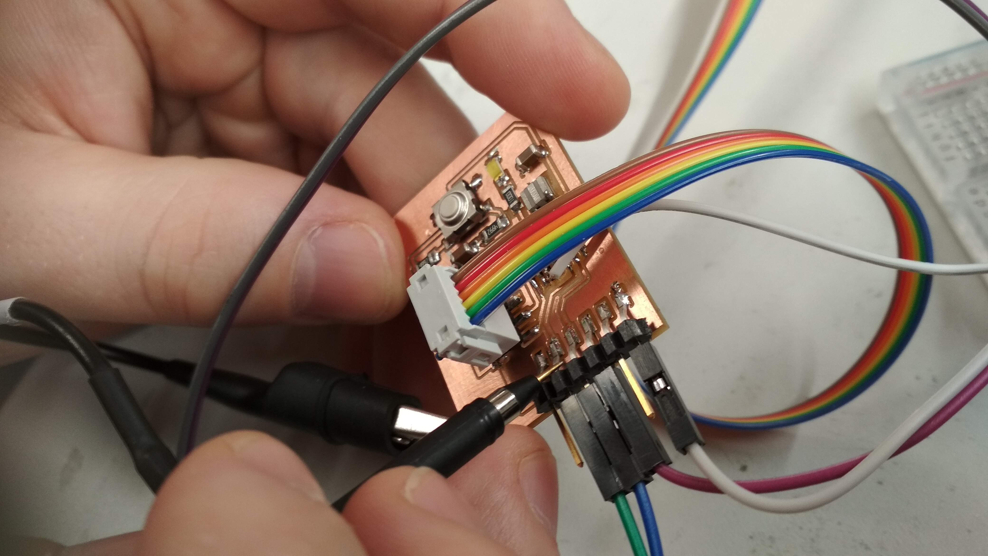
I designed the board using Eagle, milling was done in Fablab. This time knowledge from Electronics production was put in practice (once again). As I made it already numerous of times this part went extremely easy and pleasant. Soldering was also trivial. I only had to lift phototransistor a bit as pads were a bit too small.
After ensuring all connections are right and there are no shorts. I powered everything up from FTDI cable. I could program it and use it from now on. The prototype was ready.
Phototransistor
From the datasheet I learned that phototransistor has resistance of 10 kOhms when no light reaching it. Resistance drops to several Ohms when fully opened. I decided to use another 10 kOhm resistor with it. It enables voltage to flip between 0 - 5 Volts. The rest is just code.
Thermistor
Circuit is very similar the only difference is that I failed this time. Thermistor resistance in ambient temperature is also 10 kOhms. The hotter it gets lower the resistance. However, the change is not that significant as with photoresistor. I was dead sure it is enough to use voltage divider circuit. Unfortunately, when using decent 50 kOhm resistor voltage drop is equal to 100 mV. It is not enough. I learned my lesson. Next time I will use bridge circuit. I already know values of components.
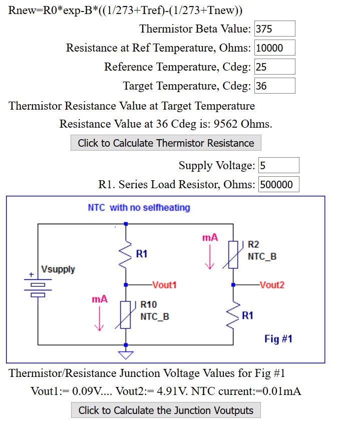
I could calculate value of bridge components by myself but WHY?. I simply used This on-line calculator. Bridge schematic is more precise and reliable and this circuit will be part of my final project. My values used for calculation were:
- Beta value: 375 (taken from datasheet)
- Resistance at Reference Temperature: 10 000 [Ohm]
- Reference Temperature: 25 [C]
- Target Temperature: 36 [C] (human body)
- Supply voltage: 5 [V]
- Load resistor: 500k [Ohms] - adjustable value
Once again Arduino code was the most of work. I read value of thermistor in the same way as I read phototransistor. Unfortunately it is really difficult to fix the value in condition loop so when warmed with finger I could sense it with 10bit ADC. Anyway, final code will be attached in Files section.
Code and Results
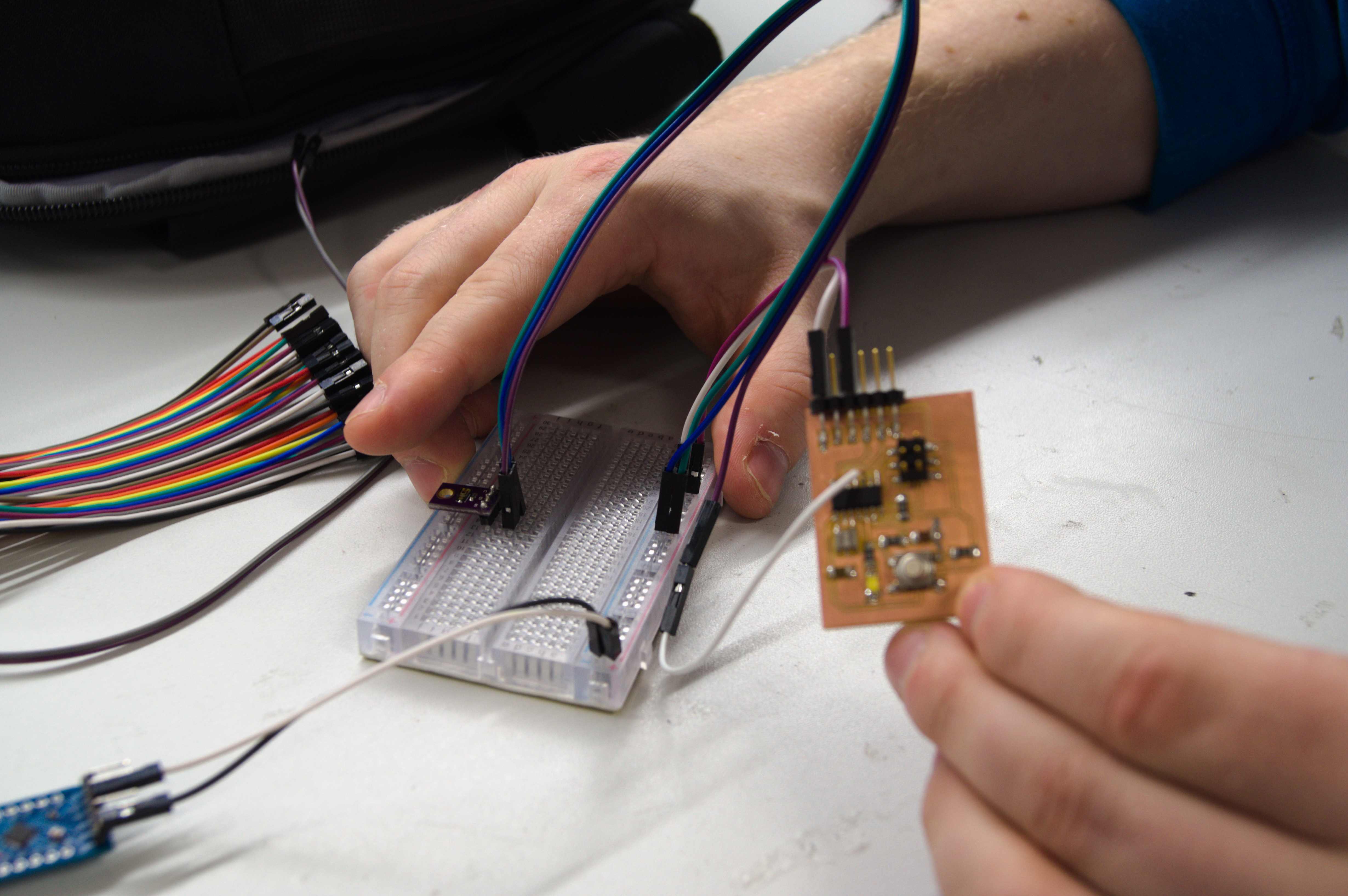
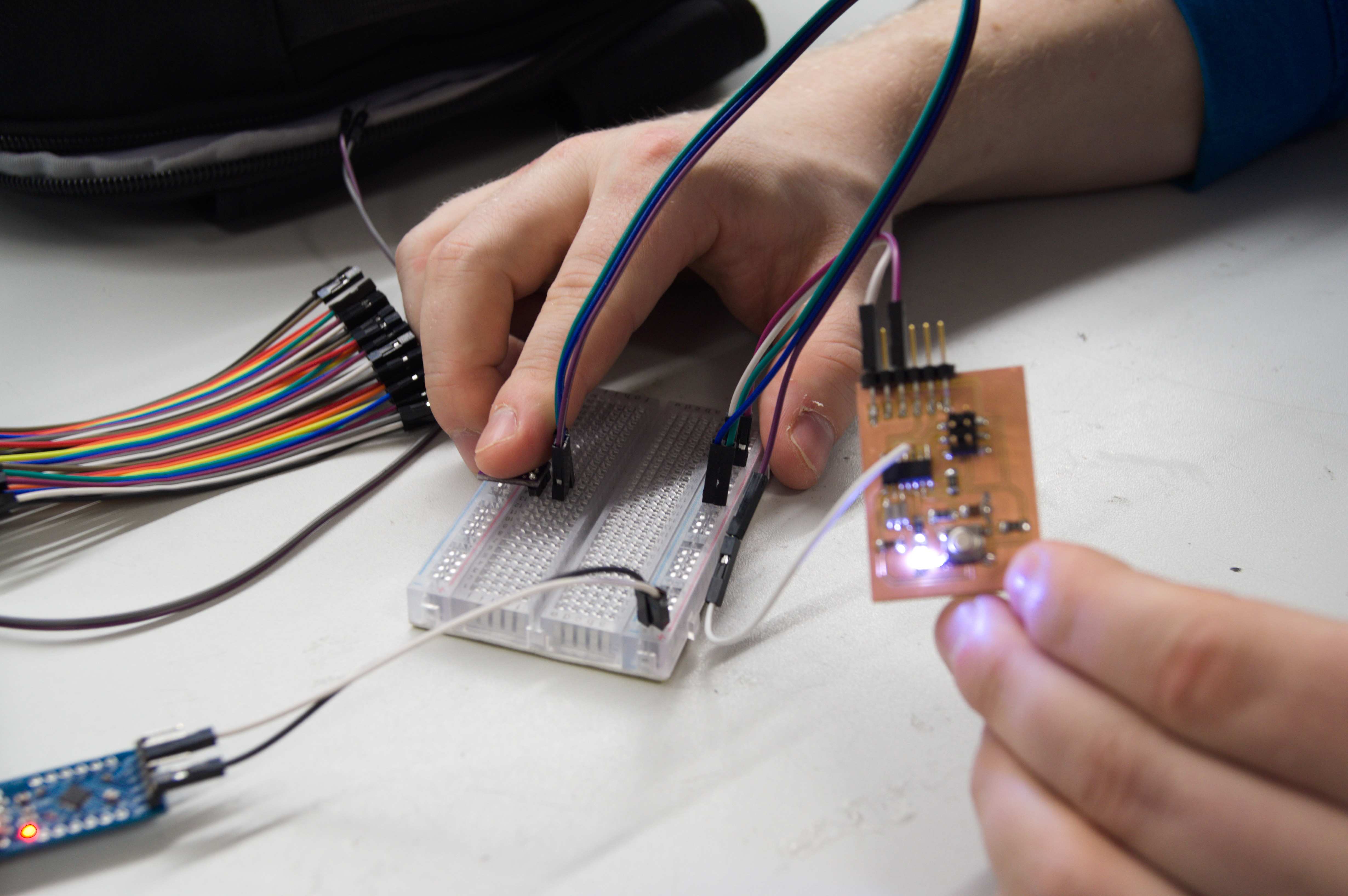
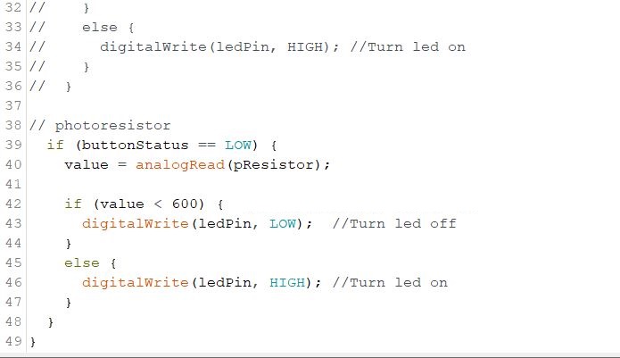
I decided to combine previous weeks. I programed my board in some new and fancy way. While button is pressed value of phototransistor is read. In case there is not enough light in the room LED will turn on. Simple and elegant. There is a bit of code below. Fully connected and programmed circuit photo is after.
The most important part of the code is presented below. Value is an integer value of defined photoresistor. Depending on value it will trigger LED.
Files:
Download: Group work codesDownload: Individual work codes
Download: Eagle schematic
Download: Eagle Board