I started concentrating on the final project implementation two weeks before the presentation deadline. The schedule was quite tight for me,
because I was a bit behind also on my assignment work. I only had a first sketch of the project.
Nevertheless, I had a clear schedule in my head and on paper, and I was confident that I had the required skills to make it.
Development Process Summary
I described the background and motivation of my project in the Applications and Implications week's report.
I also gave a short summary of the aims and the development process steps there.
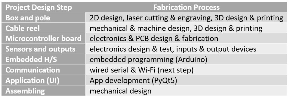
So, here, I will go directly to explaining the development steps. Fig. 1 shows the different steps of the process that
I took (and the parts that were designed) and assembled for building the project, and the skills that were required by each:
Figure 1. Project development steps.
In the following sections, each of the steps are explained and the following questions are answered about each:
What questions were answered in the process? How was it evaluated? What were the implications? What materials and components were used,
where did they come from, and how much did they cost? What has worked in this step and what has not?
What questions still need to be resolved? What did I learn?
Box and Pole
I decided to make a wooden box for the block heater,
but I wanted it to have curved sides instead of a simple box with sharp edges.
Since the only available option was 6mm-thick pine plywood,
and I needed sides that were tens of centimeters wide, I thought of stacking and gluing.
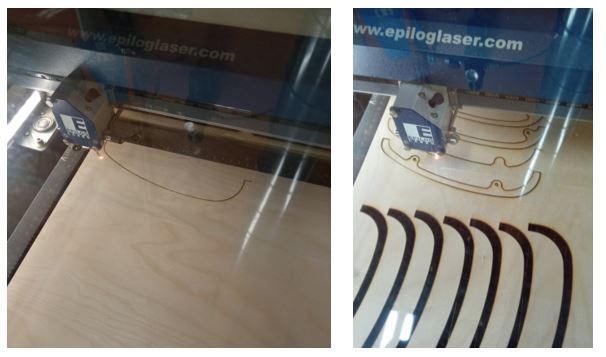
I fabricated (by laser-cutting as in Fig. 2) multiple 6mm-wide curved sticks
and combined them to create the thickness that I needed.
A video of the laser-cutting process is also shown.
Figure 2. Lasercutting process.
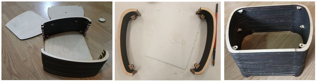
I stacked the side/top/bottom parts that I had laser cut and glued them together with wood glue.
Figure 3. Unassembled box parts.
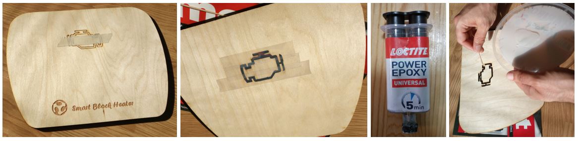
As the LED display, I laser cut the shape of an engine in the front panel,
so that only the pattern edges were cut out. Then,
I fixed the middle part with taping it from the back and filled the empty edges with epoxy.
Figure 4. The logo and LED display.
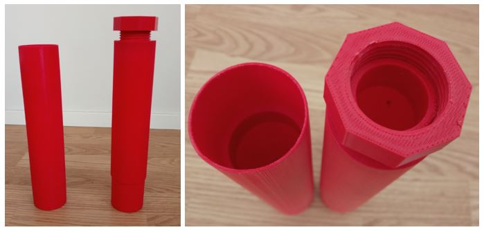
I 3D printed the pole. It consists of two parts that can be pressfit together.
The bottom part will be fixed into a lasercut wooden base,
and the upper part is threaded and will be fixed into the box with a 3D printed bolt.
I sanded the pole, pre-painted and then spray painted it brown.
Figure 5. The pole.
Cable Reel
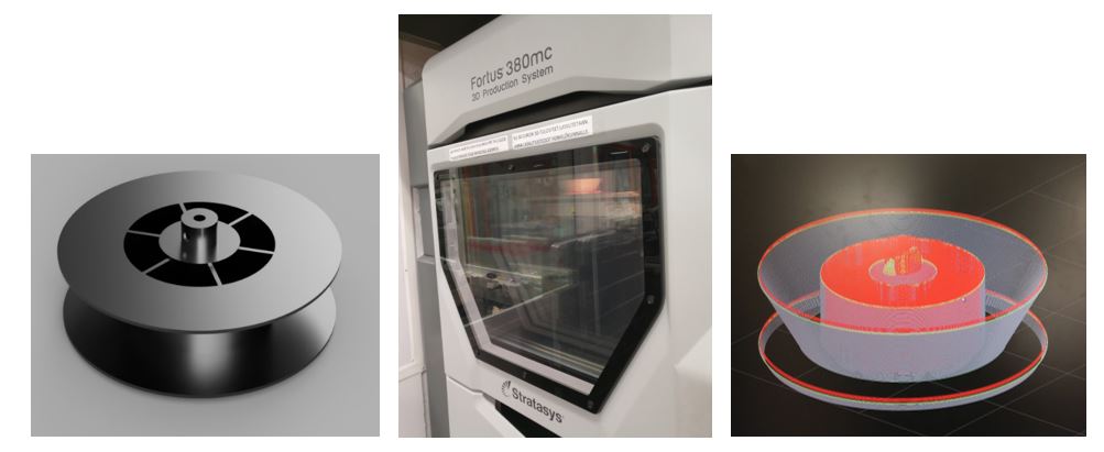
The reel was designed, and 3D printed. The size was adjusted to accommodate
a desktop monitor power cable, and it should be connectable to the motor.
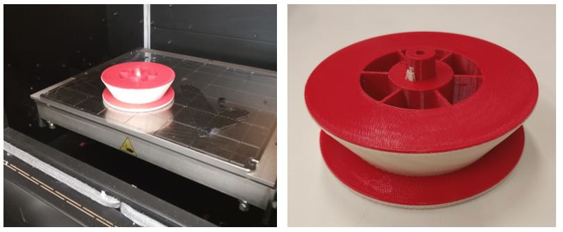
A video of the 3D printing process of the reel is also shown.
Figure 6. The reel designs and in making in 3D printer.
Figure 7. The reel after printing a before solution.
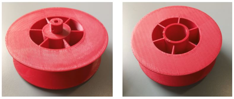
Figure 8. Front and backside of the reel.
Microcontroller Board
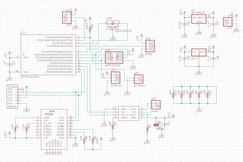
The schematics of the designed board is shown in Fig. 9.
I used an ATTiny44 microcontroller for my final project,
since I had gained experience using it in the assignments.
Each of the different parts of the design (inputs, outputs, communication …),
their functionalities,
their implementations, challenges are explained in detail in the following sections.
Figure 9. Schematic of the designed microcontroller board.
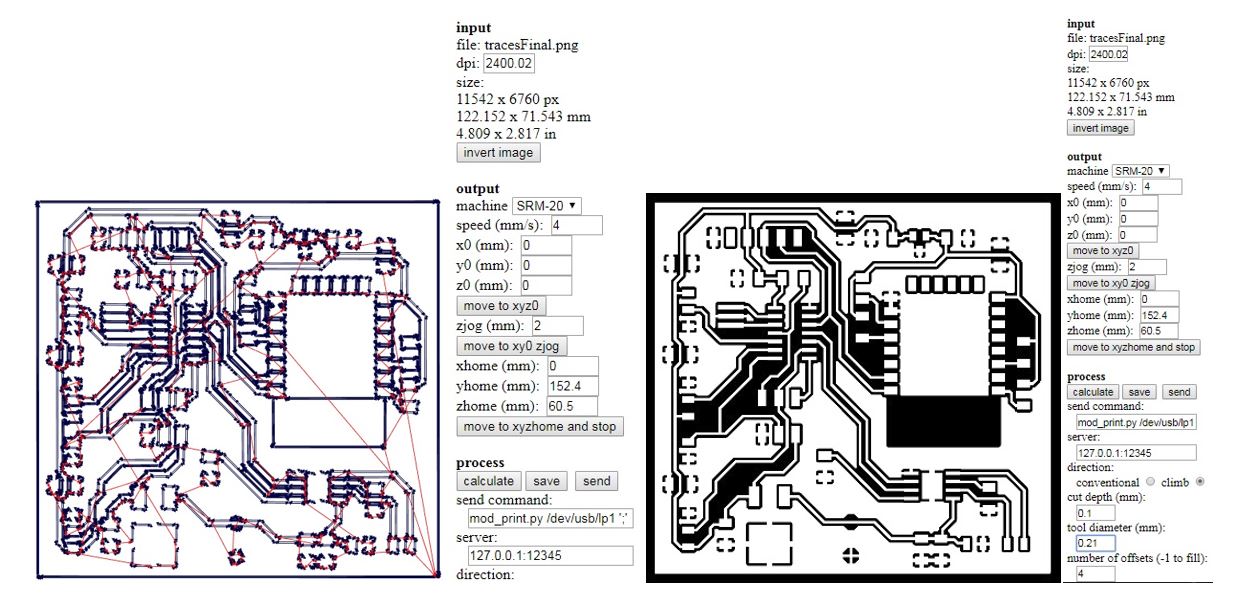
The PCB design was a bit challenging, because I wanted to have everything
on one small-sized PCB (so that it would fit inside the box) and in our FabLab,
only making one-sided PCBs is possible. So, figuring out the wiring pattern took some time.
A video of the PCB printing process is also shown.
Figure 10. Milling RML file and settings.
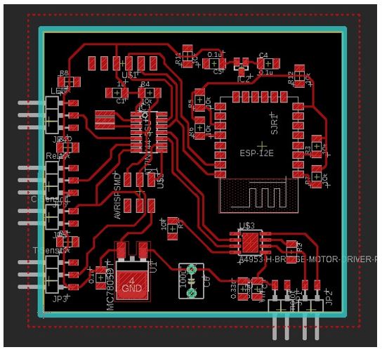
Figure 11. The PCB layout design.
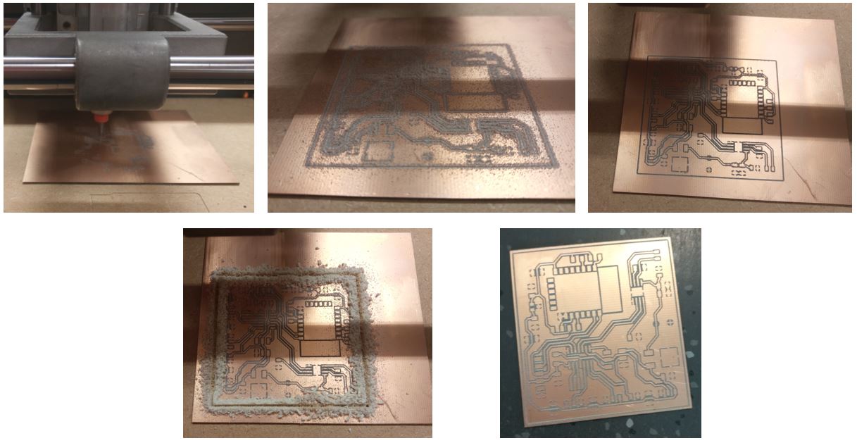
Figure 12. Fabricating the PCB.
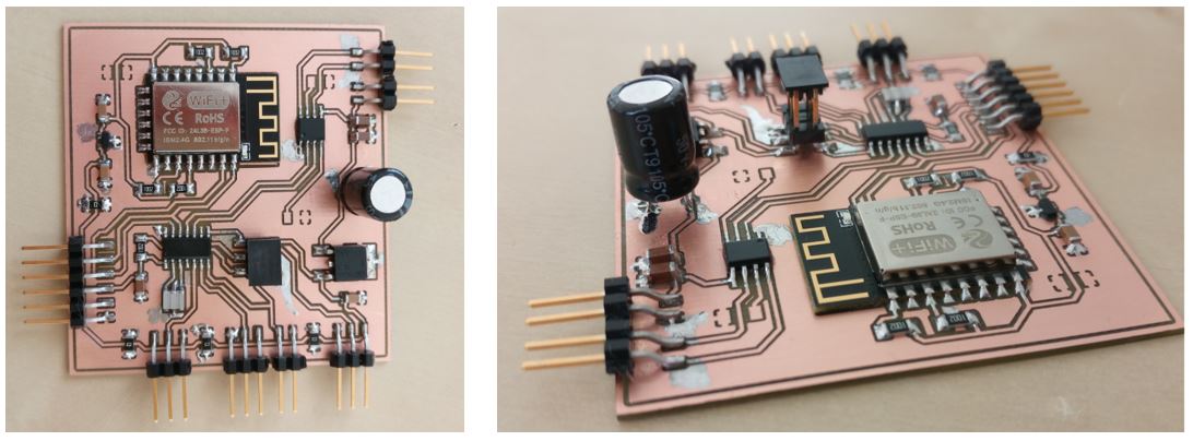
Figure 13. The board after soldering the components.
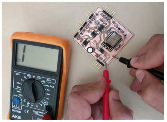
Figure 14. Testing the board and soldering for unwanted shorts.
Sensors and Outputs
My project had a temperature sensor,
and three outputs (a motor, a relay and LED).
The outputs and their test procedure and results were
explained in detail in the Output Week. So, here I will add about the input:
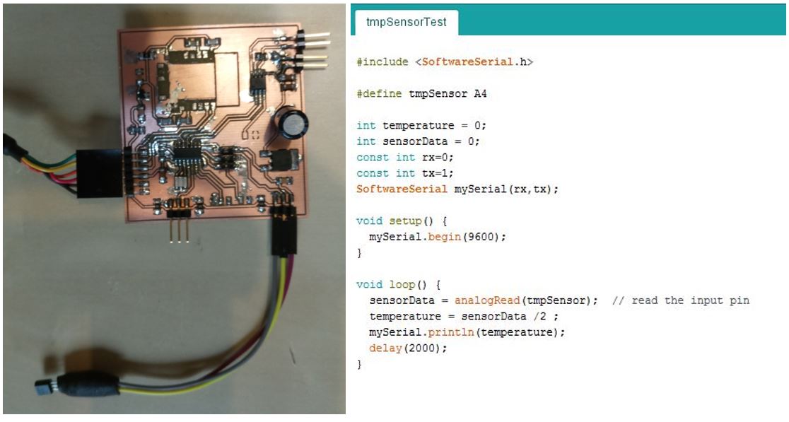
The temperature sensor that I used was a LM35. I tested it by reading its temperature in
the normal ambient condition and then I heated it and monitored the change.
Figure 15. Temperature sensor.
To test the temperature sensor, I used the following code.
In normal ambient temperature, the sensor measures 29 degrees.
For further testing, I put the sensor close to a working laptop’s fan
and monitored the temperature change over time.
A video of this test is shown below.
Figure 16. Temperature sensor’s test and test code.
As the assignment of the Output Week, I designed and tested each of
the outputs separately, and got positive results. On the other hand,
I had also tested the serial connection separately.
However, when I got to this point in the final project,
I tried to combine these two functionalities in my code,
but I could not get a positive result. After a lot of speculation,
I found the problem. Both The serial connection and LED
control libraries use interrupts timed with the only integrated
timer available in ATTiny44 and this was causing timing issues.
To solve this, one option was to change the microcontroller
to one that comes with an integrated UART module or at least
more than one timer. This would cause many changes to
the project electronics, which I could not afford to do at this stage
(owing to limited time I had available before the deadline).
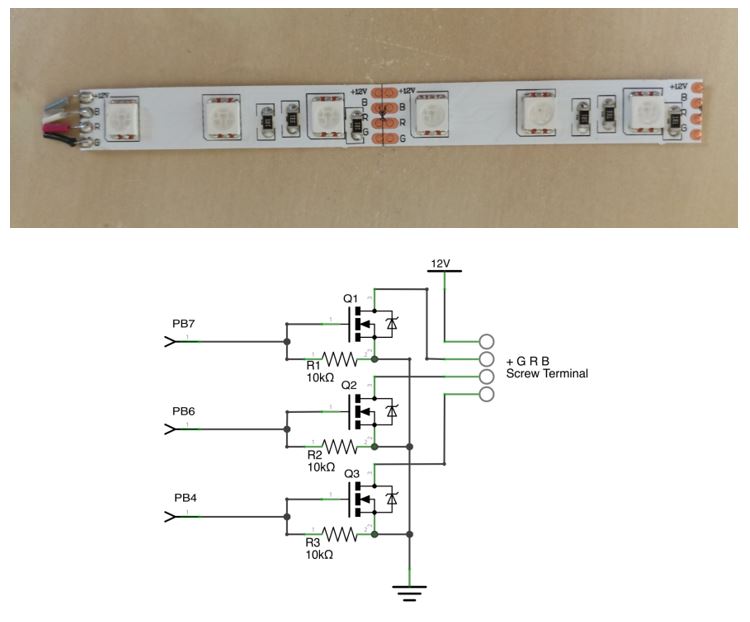
Therefore, I decided to go with my second solution that was changing the LEDs to a 12V RGB LED strip.
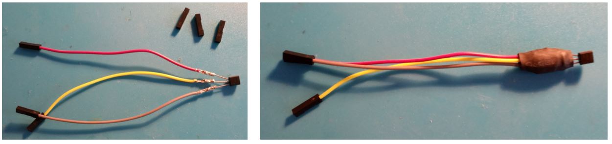
Figure 17. 12V RGB LED strip and bias circuit.
I built the biasing circuit and wrote a code for controlling the 12V LED strip.
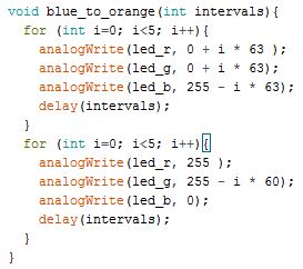
The configuration and code is shown below. One challenge was to write the code for gradually changing
colors of the LEDs during the timer run but I finally managed to do it by dividing it into two loops.
Figure 18. 12V RGB LED strip configuration.
Figure 19. 12V RGB LED strip test code.
Embedded Software
The embedded code, which was programmed and for the ATTiny44,
has the following features:
- It releases and rolls up the cable at user’s request
through the UI by controlling the motor.
- It receives a time duration from the UI, which specifies after
how many hours the engine needs to be warm and ready.
- It receives the temperature from the input sensor and calculates
the optimum time after which the heater must be switched on,
for the engine to be efficiently heated.
- It sets a timer that counts down to ‘turn on’.
- When the ‘turn on’ timer runs out, it connects the relay,
and sets a timer that counts down to ‘turn off’.
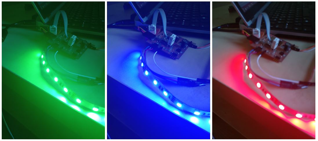
- At the same time, it turns on the display LEDs, and changes
LED colors according to the remaining time of the ‘turn off’ counter
(from blue/cold to orange/warm.)
For testing purposes, every 1 minute was considered 10 seconds
in the code.
The calculation of the timer values based on temperature is done
very simply here, just to depict the possibility.
To implement this efficiently, tests in real situation is probably needed.
The codes are added in the Files section.
Communication
There are two communication possibilities embedded on the board.
The first one is a wired serial connection through an FTDI cable
to a PC. After the physical check of the board, I programmed
the microcontroller with a test code that sends a known number
to the serial port. This was just to make sure that the ATTiny44
works properly (all test codes can be found in the Files section).
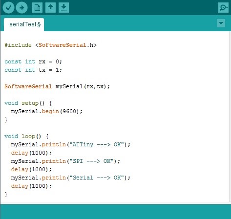
After this step, I programmed a simple test code (Fig. 20)
to make sure the microcontroller can be
programmed and that the basic communication functionality is OK.
Figure 20. Serial test code.
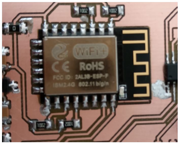
There is a wireless communication possibility also
included on the board. ESP8266-12E, when used as a Wi-Fi adapter,
adds wireless internet access to my project. Microcontroller can be
connected simply through SPI/SDIO or I2C/UART interface to this.
Fig. 21 shows the IC soldered on my board.
Figure 21. The Wi-Fi IC and antenna.
This feature of the system is not implemented yet and
was just integrated on the board to add the wireless communication
functionality in later development phases. Although the wireless
feature is not tested yet,
the needed electronics and PCB is designed and implemented already.
Application (UI)
For interacting with the smart block heater, and testing the
functionalities, as the first step, Arduino’s serial monitor was
used to deliver the commands
through the serial connection.
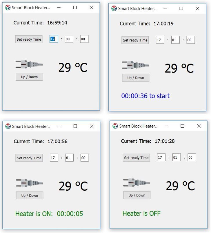
As the next step, a desktop user interface application was
designed and implemented using PyQt5 to implement the tested
functionalities through a graphical interface. A preliminary version of this interface was build
as Interface and Application Programming week's assignment.
All the features are explained there. The only addition was the implementation of the cord roll up/down
function, and displaying the temperature.
Fig. 22 shows a few snap shots of the application.
Figure 22. Desktop UI snapshots.
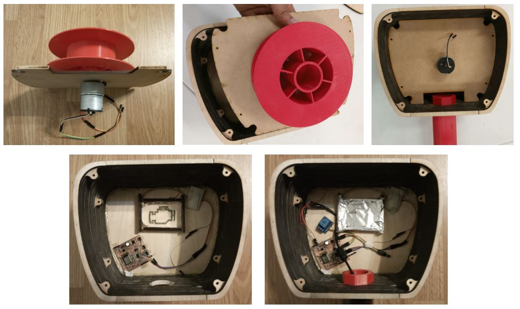
Assembling
Fig. 23 shows different steps in assembling the final design.
Figure 23. Assembling the project.
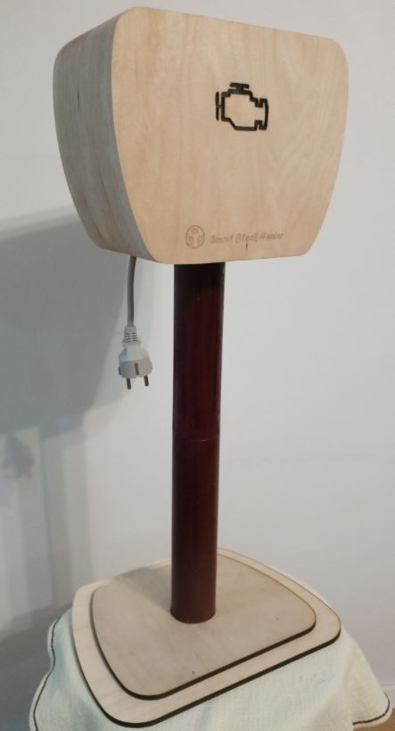
And here is an image of the final result:
Figure 24. Assembling the project.
Summary
What tasks have been completed and what tasks remain?
Completed tasks: Design and fabrication of the box, design and fabrication of the pole and stand, design and
integrated implementation of microcontroller board (a single PCB incorporates all elements), design, fabrication and implementation
of motorized cord reel, implementation of temperature sensor and temperature-optimized timer, implementation of HV relay,
wired serial communication to a windows-based UI, PyQt5-based desktop UI for setting up the block heater timer and remote control of cord reel,
implementation of RGB LEDs for displaying the heating status. Remaining tasks: Testing the already included current sensor for calculating and reporting user consumption,
testing the already included wireless connection via the WiFi IC, implementing an Android-based app to support remote wireless connection.
What has worked? What hasn't?
All the above-mentioned completed tasks have been tested and worked. while building the LED display, I had to compromise and use a 12V RGB LED strip
instead of 5V addressable LED strip, which I was planning to use. This was because both The serial connection and LED control libraries
use interrupts timed with the only integrated timer available in ATTiny44 and this was causing timing issues. But the design worked well
also with the 12V RGB LEDs.
What questions need to be resolved?
Can this prototype be fabricated with lower cost? Can it be implemented with material that endure outside conditions in subzero temperature?
I saw a clear need for a more sophisticated microcontroller during the development process. What are the exact specifications that the
new microcontroller should have to be able to handle all the functionalities?
What will happen When?
The functionality of project is already explained in detail (here and in Final Project page).
I will add the WiFi communication, Android app, and consumption record via current sensor. Then,
I need to start thinking about if I want to continue working on this further or not?
What have you learned?
The main learning outcome of this project for me was how to handle and schedule a project in a short time, to think fast, work hard and make
the right decisions and compromises to deliver a multi-dimensional project on time. I used a new method for fabricating a box with curved edges
using thin plywood (which I was thinking to try for sometime now!). While making the bill of material, I got to really find out and think about
how much the parts cost. I had a clear knowledge of electronics cost, and I had already included the cost parameter in choosing my electronics elements,
but not so much for the wooden or 3D printed parts.
Reflection
I have to admit that I was tested to my limits to deliver this project in time.
There is still a lot of room for improvement with this project: some extra features can be added,
more sophisticated codes and algorithms can be implemented ... I'll add more about the future work in the project page.