Week's Assignments
In this week's assignment, I will explain my final project and its features, the motivation behind it,
the materials and components used in it (together with their source and cost), different parts of the project and processes used to make them,
and evaluation and implications of each.
Background
Conventional Car-heating (Fig. 1) is timer-controlled. There is a timer for each plug socket,
and the user can set it as needed for two hours. When you want to set the heating time,
you need to turn the outer ring of the timer clockwise until the red arrow points at the time that you want your car to be ready for use.
For example, if you want your car engine to be warm at 3 pm (i.e. at 15.00 on the 24-hour clock),
turn the outer ring so that the red arrow points at number 15. The heating will start at 1 pm (i.e. at 13.00 on the 24-hour clock).
The green arrow on the ring shows the time when the heating starts.
The white triangle outside the ring of the timer must point at the current time.
 Figure 1.
 Existing block heater.
Some of the disadvantages of this system are:
• User does not always know when he/she is going to use the car next time.
• The system keeps the heater turned on for two hours regardless of the ambient temperature
(it does not matter if the weather is - 5 or - 25 degrees).
• The block heater door has a lock that is sometimes frozen in winter,
and the user struggles when he/she wants to change the timer values.
• Parking fee for the block heater is fixed
(regardless of the amount of electricity that the user has consumed).
• Usually users keep the cables plugged in the socket at all times,
because the subzero temperature stays for at least a few months.
Therefore, when the car is not in the parking, the other end of the cable had to be protected by a lid,
and the user should make sure that it is not exposed to rain or snow, while unplugged from the car.
In the open parking areas, this usually means careful wrapping of the cord around the block heater
in a way that the unplugged end faces downwards and does not touch the snow!
Design Features
Inspired to find a solution for these issues, in my final project,
I decided to redesign a block heater. My design will have the following features:
• The user can set the timer remotely
over the internet using a mobile app (an Android application).
• A ESP8266 module embedded
with an AVR microcontroller provides the data transfer capability over the internet.
• The system has a temperature sensor to measure the ambient temperature.
• The obtained temperature data can be used to set the timer more efficiently.
• A current sensor will measure the electricity consumption.
• A relay will be used to turn the heater on and off by microcontroller command signals.
• The block heater pole will have a motor-controlled cord reel; therefore, the users do not need to carry his/her own cord or
worry about it plugging it in and out or wrapping it every time.
• RGB display LEDs for tracking timer’s on/off state and the remaining time.
I could not find any block heater related project in Fab Academy. This is probably because
the problems that I am trying to solve with this design are very specific
to northern countries like Finland. Having lived most of my life in a much southern
country, I had never heard of block heater either, before moving to Finland a few years ago!
I did all the design and implementation of the smart block heater on my own.
However, I used a few Arduino libraries for my sensors and outputs,
which I referenced in the explanation of the development process.
The design of the electronic part of the project was not new for me.
I had worked with different temperature sensors before. For example, in my Electrical Engineering Master's Degree project,
I used an LM35 and a PT100 to measure the temperate variation
on each side of a Thermoelectric Generator. I also had driven multiple AC loads (e.g. coil, heater, lamps, etc.) up to 16A using
either magnetic or solid-state relays. But, regarding mechanical parts of the project, I did not get the idea from fab academy projects,
instead I learned from many helpful videos on YouTube.
Materials & Components
The material and components that I plan to use mostly come from Fablab Oulu's inventory.
In the following table, a list of the material and their prices is given. Therefore, the prototype cost is 57 euro.
More detail about the components' and materials' features in the Project Development page.
 Figure 2.
 Materials and Components
(
a and
b).
Development Steps & Processes
The planned steps are as follows: Design and fabrication of the box and the pole, design and fabrication of the retractable cable mechanics,
research for suitable sensors and outputs,
design and fabrication of electronics (PCB and circuit design and test),
implementation of the embedded software, and assembling the final design.
The processes that I will use for implementing the project are shortly:
• 2D design and laser cutting for fabricating the box.
• 3D deign and printing for the cord reel.
• Circuit design, PCB design, milling and soldering for the electronic parts (microcontroller, sensors, motor driver, etc.).
• Input device integration of temperature sensor.
• Output device implementation of relay, LEDs and motor.
• Embedded programming of the microcontroller.
Fig. 4 shows the different systems and the parts that were designed and assembled for building the project,
and the processes that were required by each:
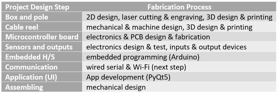 Figure 4.
 List of project's parts and involved processes.
All the parts and systems are explained in detail in the 'Project Development' week.
I give a short summary of the designed and implemented parts here (Fig. 5):
- The box was made of 6mm-thick pine plywood with curved sides.
stacked the side/top/bottom parts that I had laser cut and glued them together.
The front of the box has a transparent LED display and engraving.
- The pole is 3D printed (two part pressfit and thread/bolt connection to box) and the stand is laser cut wood.
- The cord reel is 3D printed and attached to a DC motor.
- The electronics is a microcontroller (ATTiny44) board, with all parts integrated on the same PCB.
- An LM35 temperature sensor, and three outputs (relay, LED strip and a DC motor)
are implemented and all controlled by the embedded code implemented on ATTiny44.
The temperature sensor is used by the embedded code to optimize the timer.
The relay connects/disconnects the system from power. The LEDs show the state of the system and the remaining time.
The DC motor is used for automatic roll up/down of the cable.
- The Arduino code orchestrates all the functions.
- The serial data connection provides communication between the system and UI.
- The desktop user interface lets the user interact with the system, change its settings,
activate/deactivate it ...
Evaluation & Implication
The project will be evaluated separately for each part of the design by designing tests,
which demand the functionalities of the part under test.
For testing the final assembled project,
a routine of block heater use will be completely tested
(user rolls down the cord and sets the ready time using the UI, the block heater
calculates on/off times based on temperature, connects the relay when needed,
updates LEDs to show remaining time, disconnects the really when timer runs out and updates LEDs to show
that heating is completed, rolls up the cord at user's request).
While developing the project, these questions should be answered:
- Can the microcontroller chip (which is a very basic one) handle the needed functionalities?
- After the prototype is tested with wired communication, will it be easy to implement it
through the already designed WiFi communication?
- Can I implement the functionalities with the hardware that I have chosen or will
I need to change sensors or outputs?
- Will there be a way to make the prototype cheaper?