Output Devices

Week's Assignments

Individual Assignment:
- Add an output device to a microcontroller board you have designed, and program it to do something.
Group Assignment:
- Measure the power consumption of an output device.
I did both the assignments on my own this week, because I wanted to include the assignment result as a part of my final project.

Microcontroller Board & Outputs

I used the board that I designed for my final project for this week’s assignments (Fig. 1).


Figure 1. The microcontroller board.

I used an ATTiny44 microcontroller for my final project, since I had gained experience using it in the assignments. All the board capabilities were not ready at this stage, but the outputs were. The details of the circuit design are presented in the Project Development Week, and here, I concentrate on the output part. Fig. 2 shows the schematic of the designed board with each output’s related circuit is marked separately. Each output is explained separately in the following sections.


Figure 2. The related circuits and connections for the outputs.

My final project has three outputs:
- A current relay, which is used to connect/disconnect the block heater form the 220V electricity supply.
- A DC motor that is used to roll a cord reel that moves a cord up/down.
- A 5V addressable LED strip, which will be used to show the on/off state of the current relay and the remaining time of a countdown time.

Relay

I used a Songle Relay SRD-05VDC-SL-C mounted on a WeMos D1 Mini ESP8266 Development Board for my project. It is very popular relay among Arduino users. This relay has 5 pins: two pins for the coil, a COM (common) pin, a NO (Normally Open) pin and a NC (Normally Close) pin. When current flows through the coil of the relay, a magnetic field is created that causes a ferrous armature to move, either making or breaking an electrical connection. When the electromagnet is energized, the NO is the one which is on and NC is the one which is off. When the coil is de-energized the electromagnetic force disappears and the armature moves back to the original position turning on the NC contact. The closing and releasing of the contacts result in powering on and off the circuits.


Figure 3. Songle Relay SRD-05VDC-SL-C mounted on a WeMos D1 Mini ESP8266 Development Board.

The maximum Current and Voltage Rating: it is the maximum current and/or voltage that can be passed through the switch are 10A@250VAC and 10A@28VDC. The Nominal Coil Voltage or Relay Activation Voltage (the voltage necessary for the coil to activate the relay) is 5VDC.

The relay usually needs some passive components for biasing (protection diode, transistor, current limiting resistor ...), but as can be seen in Fig 2, my schematic does not have any. This is because this relay comes with biasing components already mounted on a WeMos D1 Mini ESP8266 Development Board. An informative tutorial on how to drive a RELAY (not a relay module) with an Arduino can be found here.

DC Motor

I used a Jameco ReliaPro DC motor to rotate the cord reel. It operates at a DC voltage of 12V, with current of 74mA, Torque of 1100 g-cm and speed of 120 rpm at its maximum efficiency. I chose a driver for driving the motor, since ATTiny44 did not have output pins that could provide the needed power. The drive IC was a Full-Bridge DMOS PWM Motor Drivers (A4953). It is intended for pulse width modulated (PWM) control of DC motors; are capable of peak output currents to +/- 2A and operating voltages to 40V and comes in an 8-pin SOICN package. Input terminals are provided for use in controlling the speed and direction of a DC motor with externally applied PWM control signals from the ATTiny44.

I attached the motor to the board and wrote a test code to test it (Fig. 4). The test alternates the motor’s direction of rotation every five seconds. A video of the test result is also shown.


Figure 4. Test configuration and code for the motor.

LEDs

For showing the block heater state, I plan to use a 5V addressable LED strip. I got these from FabLab. Each RGB LED can be individually addressed using a one-wire interface, allowing a full control over the color of each. The combined LED/driver of these LEDs make them very compact.

I first found a guide on how to control Individually addressable LEDs using Arduino. For programming the Arduino, it suggested to use the FastLED library. I tried it, but unfortunately it was too large for my microcontroller’s flash (ATTiny44). So, I had to do more research and I finally found another guide, which specifically used a simple ATTiny microcontroller. It suggested another library called NeoPixel, which worked well. The test code and configuration are shown in Fig. 5, and a video of the test result is also shown.


Figure 5. Test configuration and code for the LED strip.

Group Work

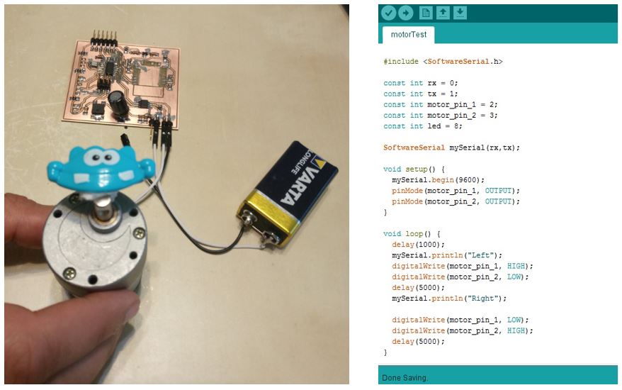
For this week’s group assignment, I needed to measure the power consumption of a device. I chose the motor for this assignment. Of course, I have previously done this measurement when I wanted to choose a suitable driver for the motor. I connected the motor to a power supply (9V) and measured its DC current consumption. Then, I chose a driver IC that had an output current suitable to my motor’s consumption. However, since I did not record it to report it, I redid the measurement. I used a multi-meter in current measuring mode series with my motor and running the same test code above, I measured the current consumption, which is around 90mA at a 9V bias voltage.
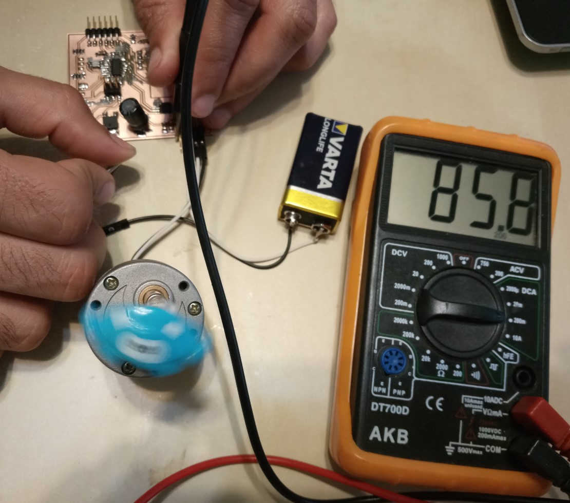

Figure 6. Measuring the current consumption of motor with a multi-meter.

As mentioned above, the code changed the direction of the motor rotation every five seconds. Although the motor has a DC current consumption, during the transitions, since the rotation needs to be stopped and restarted in the reverse direction, there is a momentary higher consumption that can be seen even with the multi-meter.

Reflection

This week, I got to test all the outputs for my final project individually.