Week's Assignments
Assignment:
● This weeks assignment was to model (raster, vector, 2D, 3D, render, animate, simulate, …) a possible final project, and post it on your class page.
Learning Outcomes:
● Evaluate and select 2D and 3D software.
● Demonstrate processes used in modelling with 2D and 3D software.
2D raster tool
Gimp
There are various photo editor software such as Adobe Photoshop,
Capture One,
GIMP, Paint.NET, Pixlr Editor,
Adobe Lightroom etc. I usually use Paint.NET and Adobe Lightroom To edit a raster picture.
Paint.NET is a freeware raster graphics editor program for Microsoft Windows, it is almost full-featured image editing program, that provides variety of tools needed for image editing. Also Adobe Lightroom is a powerful
photo editing photo especially when it comes to the lightening correction features. So I use the combination of these two software to edit a raster picture. However I am satisfied with Paint.Net, To learn a new software
I decided to use GIMP as a raster picture editor during the FabAcademy. GIMP is a free software which can be run on Windows, Mac, and Linux operating systems. Therefore I easily downloaded and installed it. Then I followed
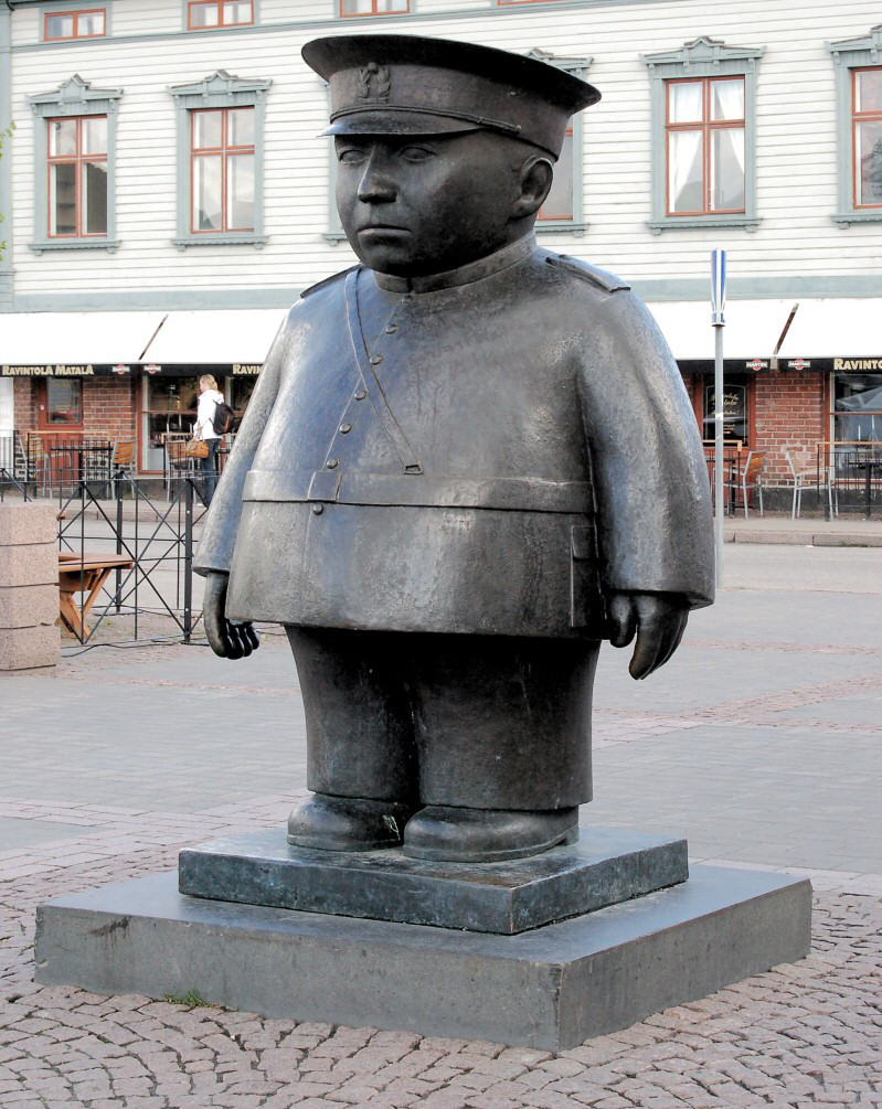
this tutorial to turn a raster photo of Toripoliisi
into logo with Gimp. Toripolliisi (The Bobby at the Market Place in English) is a bronze sculpture located at the market square in Oulu.
These are the steps that I took to make the logo:
1. Remove the saturation from the photo to turn it to black and white. Then use the Curves function to deepen the shadows a bit (Figure 1-2).
2. Add a new layer on top of the image by clicking on Create a New Layer icon located in bottom right toolbar.
3. Bring the opacity of the created layer down to 30 percent.
4. Select Paintbrush tool and trace over outline of the subject.
5. make the size of the brush smaller and trace over the shadows.
6. Add another new layer and fill it with white color, then bring that down beneath the layer that we previously created. It helps to see the traces better.
7. Use the Bucket Fill tool to fill the shadows (Figure 1-3).
8. Bring the opacity back up to 100% and use the Threshold function to make the sketch entirely black (Figure 1-4).
9. Export the design as PNG file.
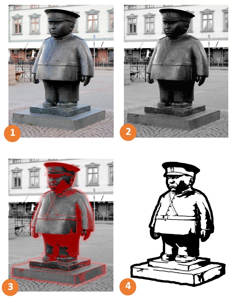 Figure 1.
 Making logo from a raster photo.
2D vector tool
Inkscape
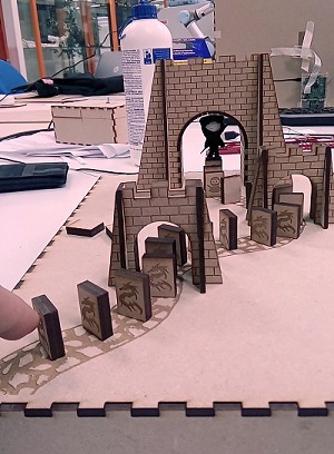 I have a basic knowledge of 2d vector designing. In some of my previous project (game, useless box, etc.) I utilized Inkscape to design the
different parts for each one. (Figure 1). Inkscape is a free and open-source vector graphics editor and I already was familiar with it, so I decided
to continue using Inkscape during fab academy as well. As a practice for this week I tried convert a graphical image to a vector image, which I had not done before.
I have a basic knowledge of 2d vector designing. In some of my previous project (game, useless box, etc.) I utilized Inkscape to design the
different parts for each one. (Figure 1). Inkscape is a free and open-source vector graphics editor and I already was familiar with it, so I decided
to continue using Inkscape during fab academy as well. As a practice for this week I tried convert a graphical image to a vector image, which I had not done before.
I found out it more convenient to hide the border while I was working on image. To do that you need to uncheck the Show page border from
Document and properties under File menu. These are the steps that I took to vectorize my image.
1. Dragging and dropping the image into the Inkscape.
2. Opening Trace Bitmap from Path menu.
3. Checking the Live Preview to see the image.
4. Playing around with Brightness cutoff to see which setting is better for the image. It is actually a threshold that determine whether the pixel should be consider black or white.
5. Setting the Edge detection. This setting adjust the darkness or thickness of the edge in the output.
6. Setting the Brightness cutoff. It tries to find edges where colors change. The setting here determine how many colors output will have.
7. Setting the Brightness steps, this let you to set the number of scan you want to have in output.
8. The output vectorize image will show exactly on top of graphical image. I dragged it to somewhere else.
9. Different layers are stacked in the output image. In order separate the layers, I did right click on the vectorized image and selected Ungroup.
 Figure 2
 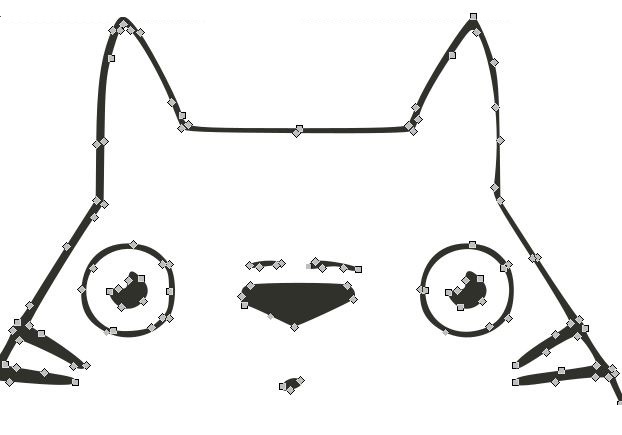 Figure 3.
 Verbalized Image
3D tool
Fusion 360
I selected Fusion 360 as the 3D tool to work with, during the Fab Academy. Fusion 360 software is a 3D CAD, CAM, and CAE tool from Autodesk. It gives a single cloud-based platform for design, engineering, and CAM.
Fusion 360 supports editing inside the browser, more importantly it is free for students and small companies.
Yriö Louhisalmi, Fab Lab Oulu stuff and a student of Fab Academy 2017, gave a lecture about Fusion 360
and how to use the basic functions in Fusion 360. It was a really good lecture and we tried several functions to get to know them. Moreover I
watched some tutorial on You Tube in order
to feel more confident to start using Fusion 360.
After some practicing I taught it is the time to make my hands dirty and start to create a 3d model. I decided to create a part of a
retractable cord reel which I am going to have in my final project. However I have a general view of my final project, still many details
are unclear. Therefore probably some of the features of this design such as dimensions should be change for the final projects.
Here is summarized the steps I follow to build the retractable cord reel:
1. Sketching three circles from Sketch > Circle > Center diameter Circle as the base of the cord reel (Figure 4).
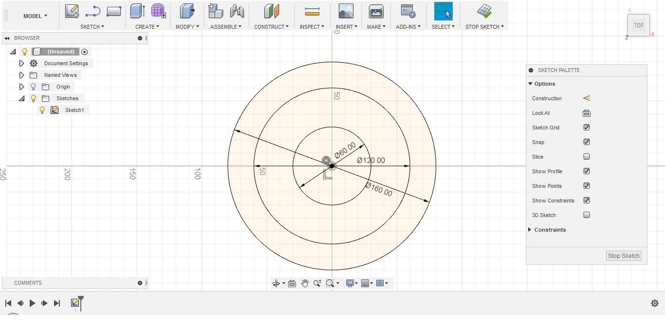 Figure 4.
 Sketching three circles.
2. To extrude the circles, Selecting Create > Extrude, click the surface and then dragging it up and setting the height I desired (Figure 5).
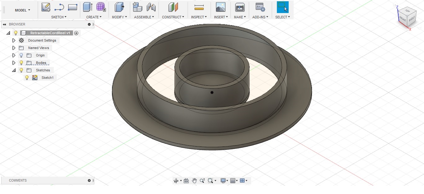 Figure 5.
 Extrude the circles.
3. Sketching a narrow rectangle from Sketch > rectangle > 3-Point Rectangle to make a blade connections between inner and outer part of the cord reel.
4. To make the drawing symmetrical click on SKETCH PALETTE > Symmetry, then take two points of the rectangle and select the line as a reference line.
5. Extrude the rectangle and set the height you desired (figure 6).
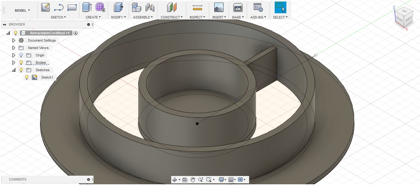 Figure 6.
 Extrude the sketched rectangle.
6. The next blade connection should have been made 60 degree shifted to the previous one. To accomplish this, I pressed L and sketched a line
started from center point and angled to the line that firs blade had became symmetrical against. The length and angle could be specified while drawing the line (Figure 7).
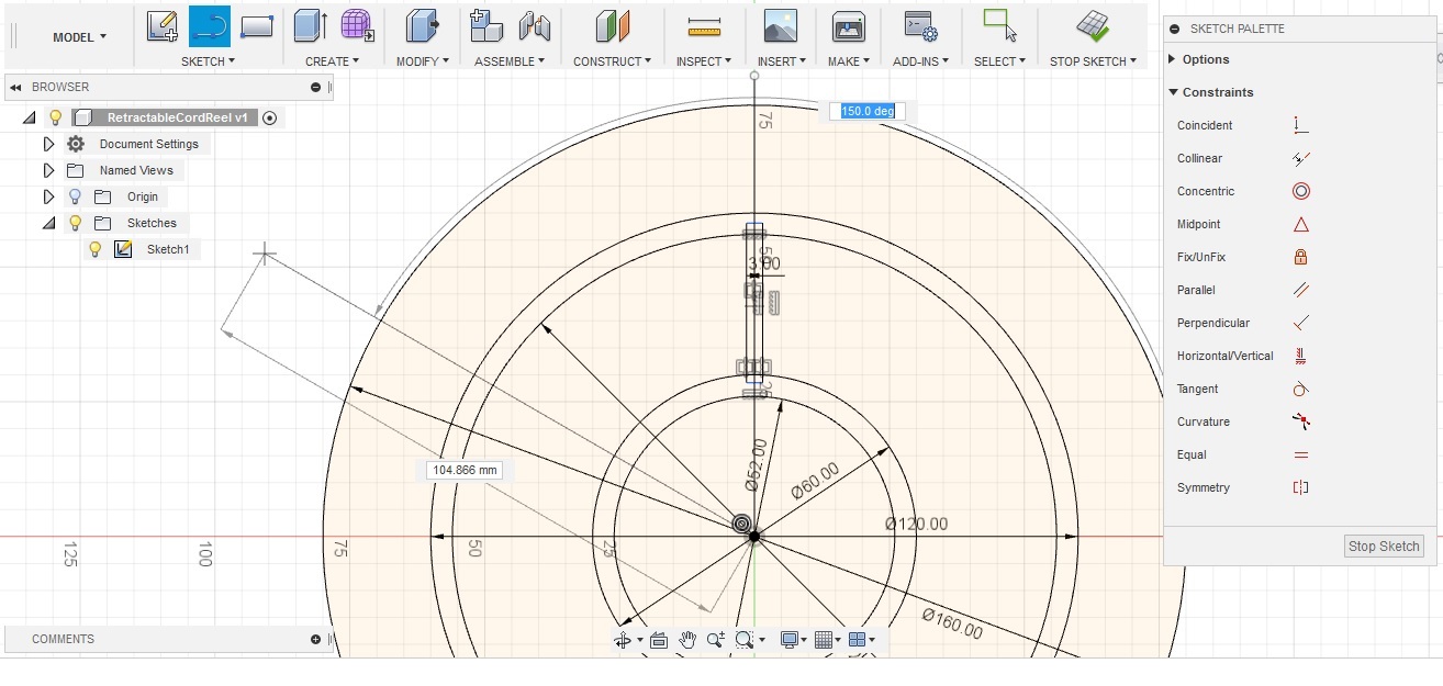 Figure 7
7. Repeating steps 3-6 to build all the six blades.
8. When the model was ready I cleaned it up by removing the extra sketches such as lines (Figure 8).
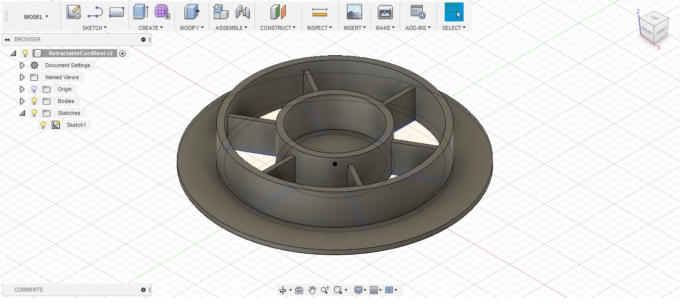 Figure 8.
 Final design.
Reflection
During this week I started using GIMP as a raster photo editor. I also learned to vectorize an image with Inkscape. I had a basic experience with 3D designing, had used AutoCAD
before for merely a couple of simple designs. During this week I got familiar with designing in Fussion 360 and designed a 3D model of a part that will be utilized in my final projects.
Regarding to the final project, the idea is quite clear, but still there is some
details that should be defined.