Week's Assignments
Group Assignment:
● Review the safety data sheets for each of your molding and casting materials.
Then, make and compare test casts with each of them.
Individual Assignments:
● Design a mold around the stock and tooling that you'll be using,
mill it (rough cut + (at least) three-axis finish cut),
and use it to cast parts.
Group Work
I did this week’s group assignment with Michael and Alok.
The task was to review the data sheets and safety data sheets for the molding and casting materials and compare test casts made with each of materials.
As always, safety is the number one priority (especially this week, because we are working with different types of material)!
Ari (Fablab Oulu instructor) explained the process of molding and casting, and general safety rules that should be maintained. So, we made sure that the ventilation worked properly,
and we wore safety glasses and vinyl safety gloves (chemical-resistant) to prevent skin/eye irritation, and long sleeves or lab coats.
In all cases, if the skin or the eye are exposed to the material, the following first aid procedures should be applied quickly:
“Flush eyes with water for 15 minutes and seek immediate medical attention. Remove from skin with water-less hand cleaner followed by soap and water.”
Then, we went through the datasheets and safety instructions of the three
different material available to us (technical bulletins: OOMOO 30,
Smooth-SilTM 940 and
Smooth-castTM 300 Series).
Safety data sheets for OOMOO 30 and Smooth-Sil 940 and
Smooth-Cast 300 were also studied.
Here is a short summary of what we learned:
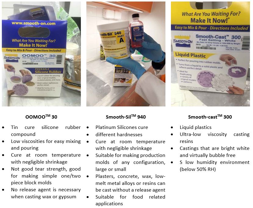 Figure 1.
 Summary of material characteristics and applications.
Table 1 summarizes the main practical information for the three mentioned materials:
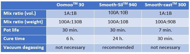 Table 1.
 Practical info for the three materials.
We were given molds that were already made in last year’s Fab Academy to cast. The following figures show the process from start to end.
A few notes: The proportions should be weighted accurately. Mixing should be done until color traces of the compounds disappear.
Vacuum degassing with Smooth-Sil should not be forgotten.
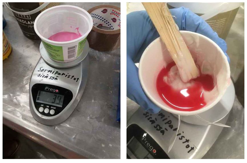 Figure 2.
 Measuring the weight and mixing the cures.
 Figure 3.
 Vacuum degassing.
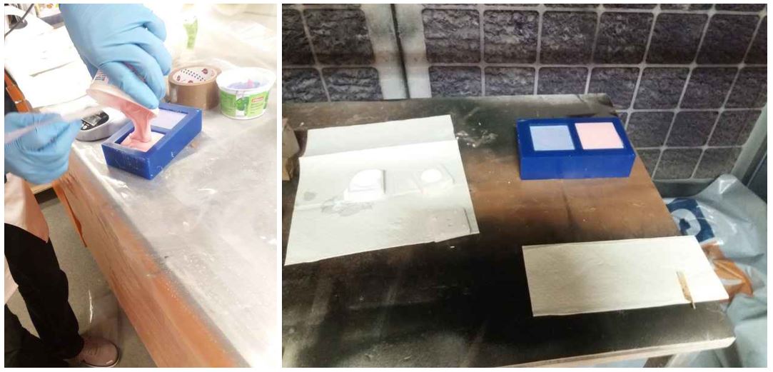 Figure 4.
 Pouring and curing.
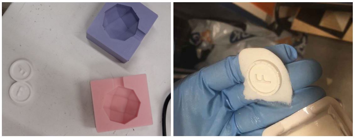 Figure 5.
 The result of molding and casting.
3D Design
I used Fusion 360 to design the 3D design of the positive mold.
The steps are illustrated below:
1- First I defined the design parameters.
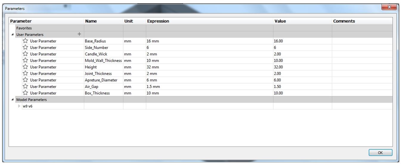 Figure 6.
 Design parameters.
2- Sketch a polygon from SKETCH > Polygon and also a circle for the candle wick, then extrude them.
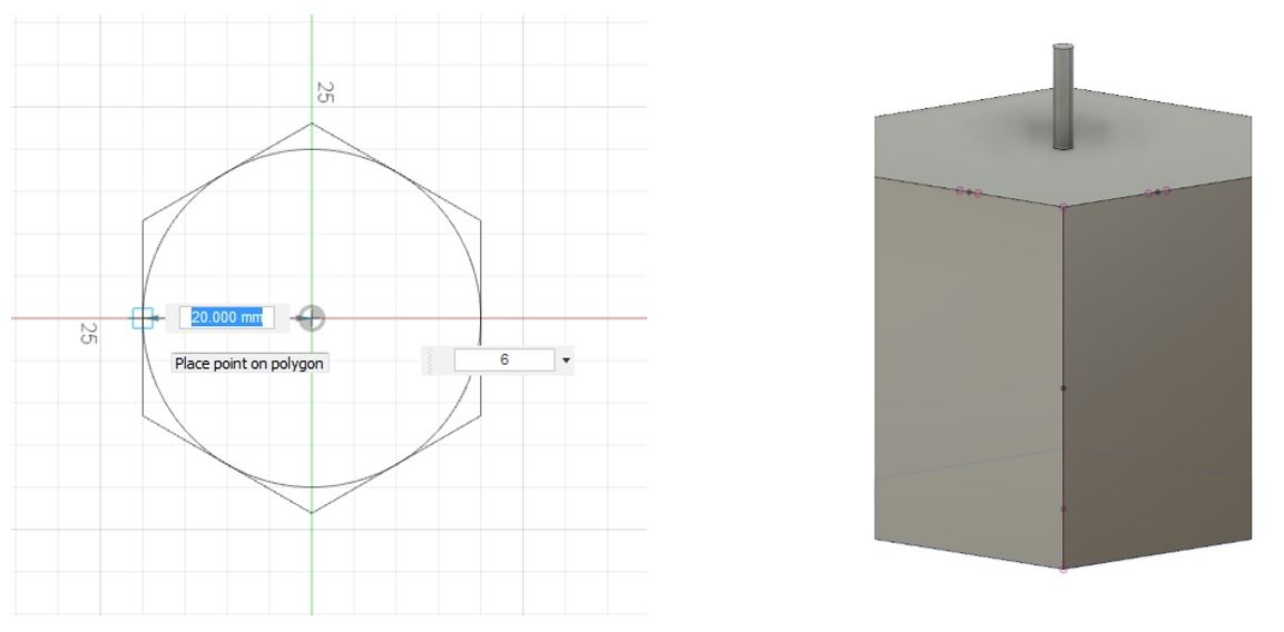 Figure 7.
 Sketch a polygon.
3- Add three points and then create a new plane from CONSTRUCT > Plane Through Three Points.
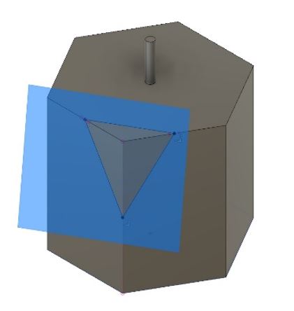 Figure 8.
 New plane.
4- Sketch a triangle through three points using Line tool.
5- Select extrude, go to SELECT > Selection Filters and only check Sketch Profile. Then, select the triangle that was made at previous step and extrude cut it.
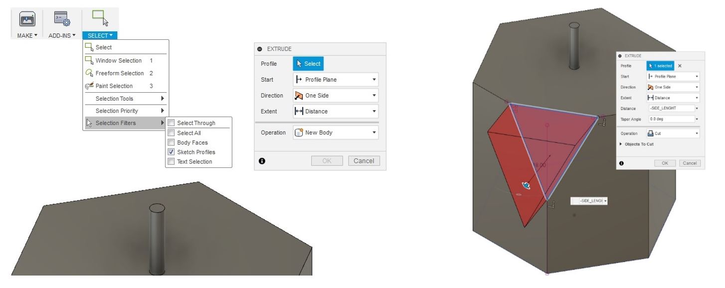 Figure 9.
 Extrude.
6- We need to repeat the steps all around the shape.
To do that, we used pattern tools from CREATE > Pattern > Circular Pattern.
Select the new surface that
we just made as the object and set the axis to the vertical one.
Finally set the quantity.
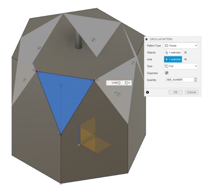 Figure 10.
 Repeat the steps all around the shape.
7- Repeat step 3-6 to form the bottom side of the shape.
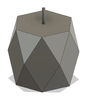 Figure 11.
 Repeat for bottom side.
We also need to make a curve body as cavity to inject the paraffin through that. To make that:
8- Sketch a vertical line, and a horizontal one, then use Spline tools to sketch the curved line.
 Figure 12.
 Make a curve body as cavity.
9- Revolve the drawn profile from CREATE > Revolve, choose the horizontal line as the axis.
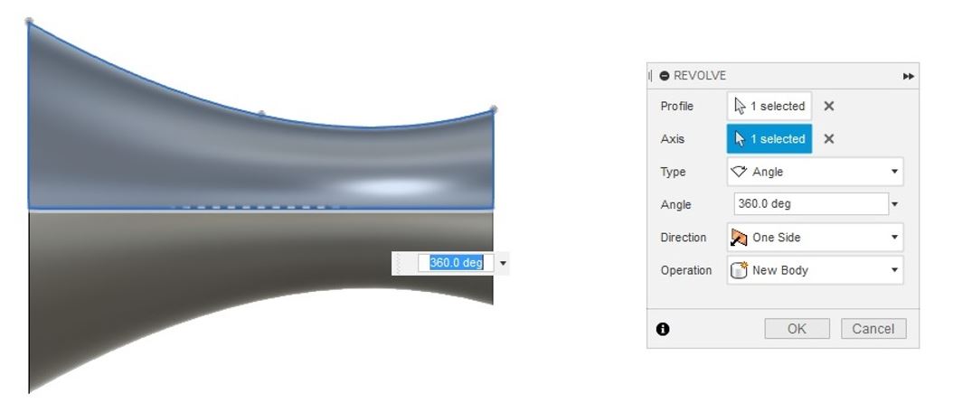 Figure 13.
 Revolve the drown profile.
10- Align the built curve model (MODIFY > Align) on top of the main design.
11- Then create a narrow cylinder as an air gap to let the air escape when injecting the material in the mold.
 Figure 14.
 Cylinder for air gap.
12- To create the frame I sketched a rectangle, extrude it and next I used Shell tool. Then I made a copy of that.
13- The last step is to split the main design and align it to the frame box. To split the main design, select its body then MODIFY > Split Body,
and then, select a panel or line as the Splitting Tool.
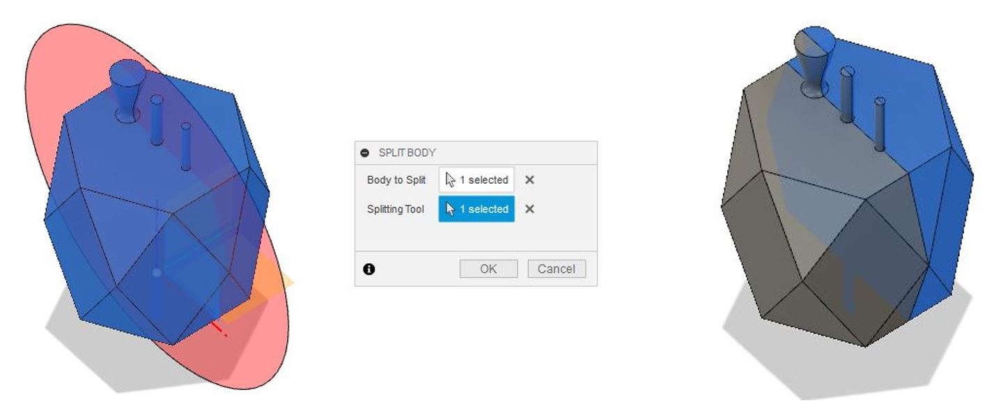 Figure 15.
 Split the main design and align it to the frame box.
Now, the design is ready, and we need to prepare a mold.
Since this is the negative mold,
we need to create a box to host the rubber silicon for the mold.
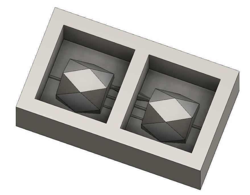 Figure 16.
 Negative mold.
Milling the Mold Design
We used MODELA Player 4 to set the file configurations for milling,
to mill out the NEGATIVE space and leaving the POSITIVE behind.
We also used VPanel to position the wax mold along the XY Z axes
in Roland SRM-20 CNC-milling machine. The selected material from the Modela was milling wax. It presets the values for the milling process.
1. Import the STL file into MODELA.
2. Set the origin to match the setting of the milling machine by: Set > Model > Origin. Make sure that the size and orientations are correct.
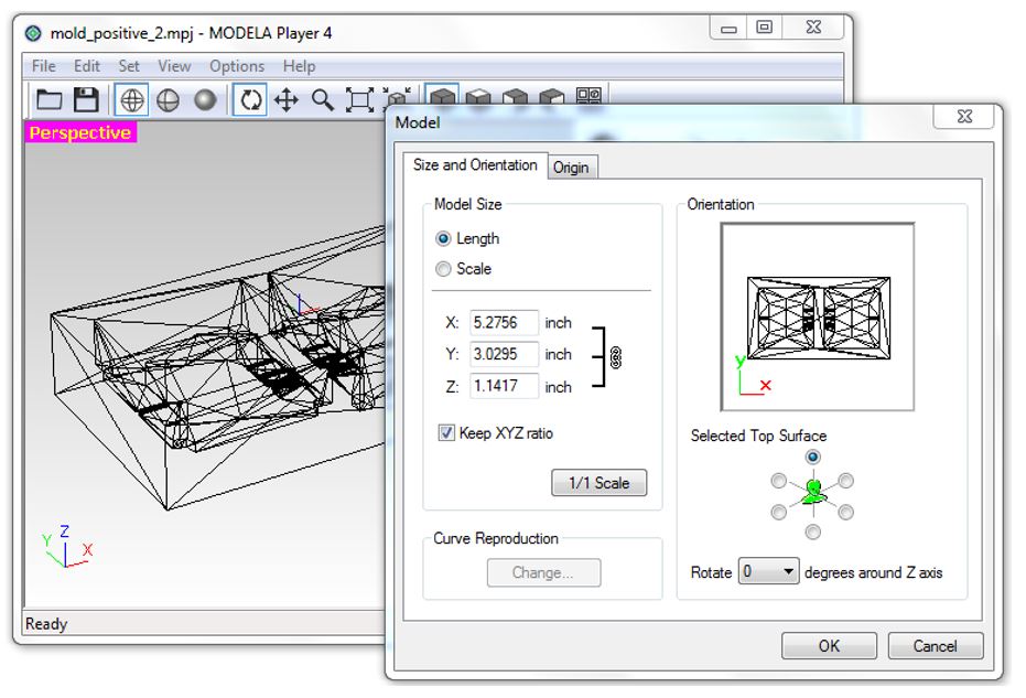 Figure 17.
 Size and orientations.
3. Set the margins by Set > Modeling Form > Margin.
Just check that the margin is zero and leave the other parameters to
their default values.
4. Create a new process by: Set > New Process. Here,
you select the tool and set the cutting parameters for the milling process.
5. Roughing process: click next. You are shown the selection of cutting surface.
6. Choose the tool for cutting (I used the default Flat 3.18mm).
7. Check if the cutting area and depth for the design are correct.
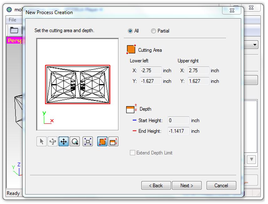 Figure 18.
 Cutting area and depth.
8. Choose the tool path to create (I chose Scan Lines (X + Y) and
Cutting Start Position as lower left).
9. Set the cutting parameters: XY Speed, i.e. the horizontal speed of
the milling tool (30 mm/s), Cutting-in Amount, i.e. the depth of the cut (1 mm)
and Path Interval, i.e. offset between parallel cuts (1.5 mm).
10. Create the tool path for the roughing process.
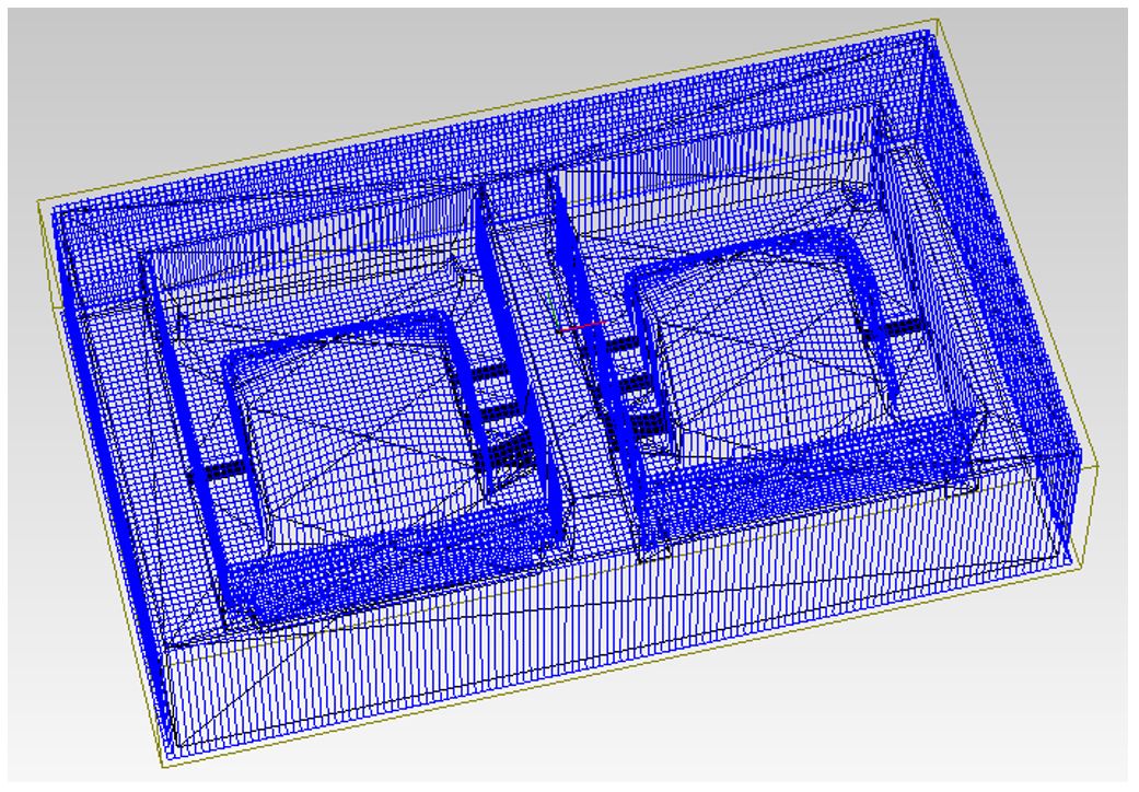 Figure 19.
 Tool path for the roughing process.
11. Create a new process again Set > New Process.
12. This time select Finishing for creating a smooth surface.
13. Change the cutting tool to R1.5 Ball.
14. Set the cutting parameters: XY Speed (24 mm/s), Z speed,
i.e. the vertical speed of the milling tool (24 mm/s),
Path Interval (0.2 mm) and the Finish Margin (0 mm).
15. Create the tool path for the finishing process. Now the file is ready.
16. Change the milling bit to flat 3.18 mm tool for roughing.
17. Place the wax mold on the base of the milling machine.
I taped both the sacrifice board (spoiler board) and the back of the wax.
Then I used hot glue gun to fix the wax on the sacrifice board.
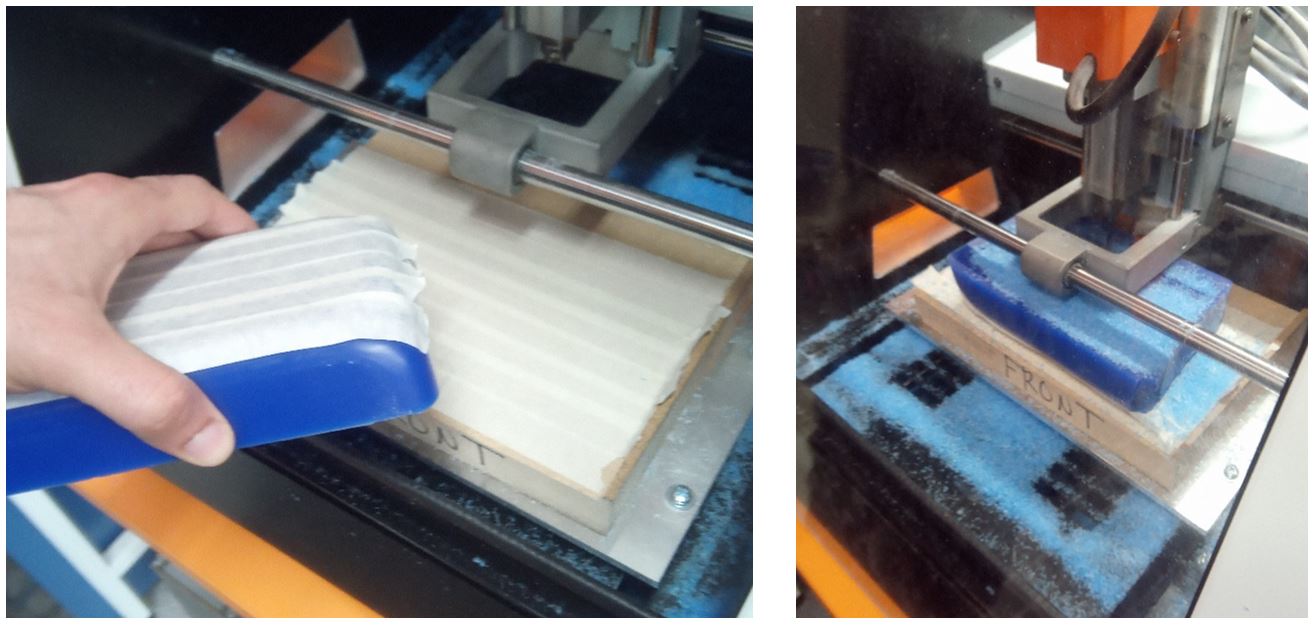 Figure 20.
 Milling machine.
18. Use VPanel for SRM-20 to position the axes.
19. In MODELA Player, press the cut button in the bottom right corner.
20. The Output dialogue box opens. Press Continue. Now the roughing starts.
Just after roughing processed got done the milling bit
were going back to its rest position, contacted the wall of the wax mold
and changed the position of that. So to do the finishing process,
I needed to do the roughing process again. Since even the roughing result was fine
for the 3D model that I had, I skipped the finishing process.
Molding and Casting
I used OOMOO 30 to make the negative mold.
The process what as explained in group work.
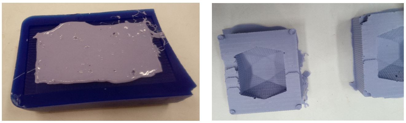 Figure 21.
 OOMOO 30 negative mold.
After the negative mold was ready, I placed a wick in the middle of negative mold
and filled it with melted paraffin to make the candle.
I used a syringe to inject the paraffin into the mold.
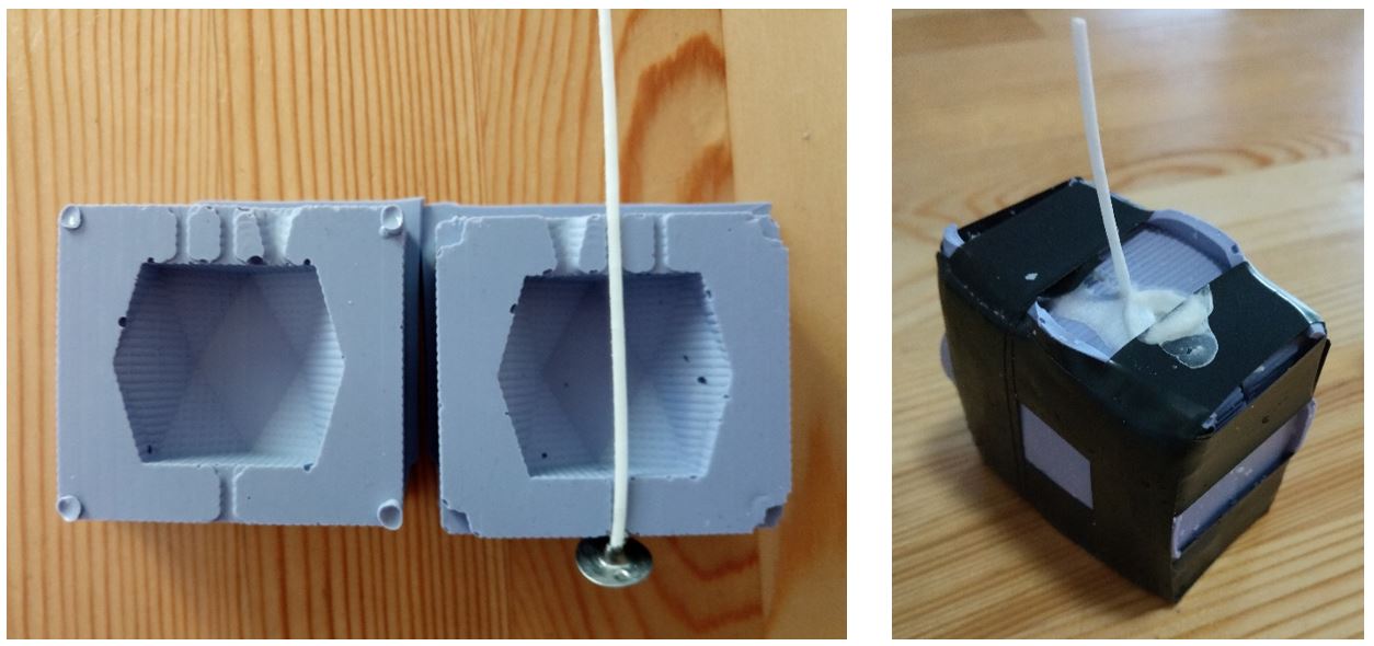 Figure 22.
 Ready for paraffin.
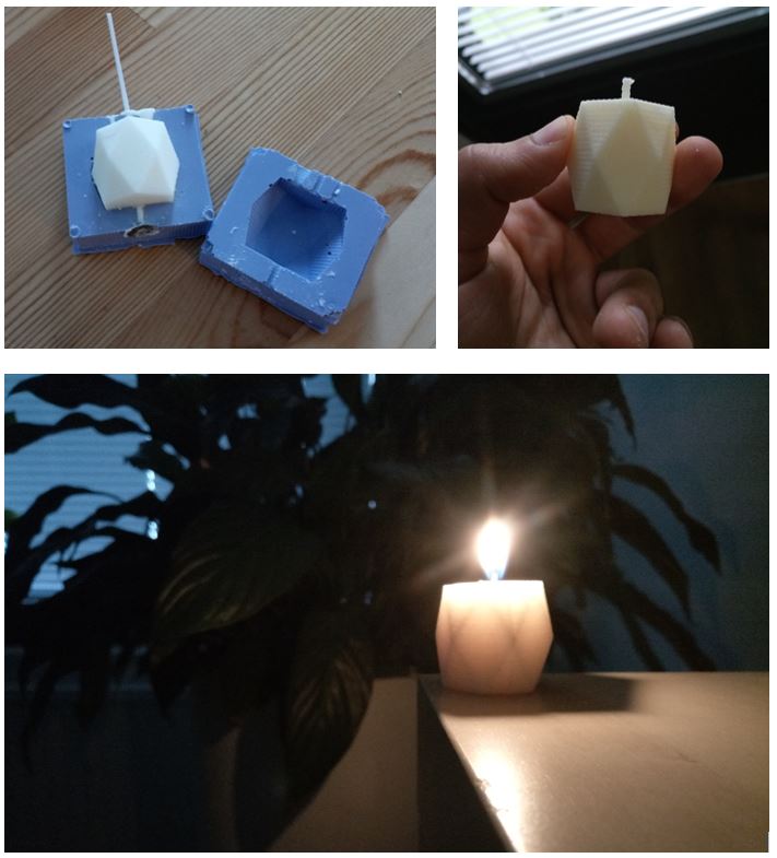 Figure 23.
 Final result.
Reflection
Nearly all we did during this week was new to me, so I learned a lot.