OUTPUT DEVICES | WEEK 11
A0 Link to group assignment.
You can see the group assignment hereDuring the of molding and casting I prepare a Polyester resin piece with 6 LEDs inside. My idea was to use this part during this week. The objetive of the week is create an output device but, since I have this piece with 6 leds I would like to create a dice using a tilt sensor.
.jpg)
Electronics design and production.
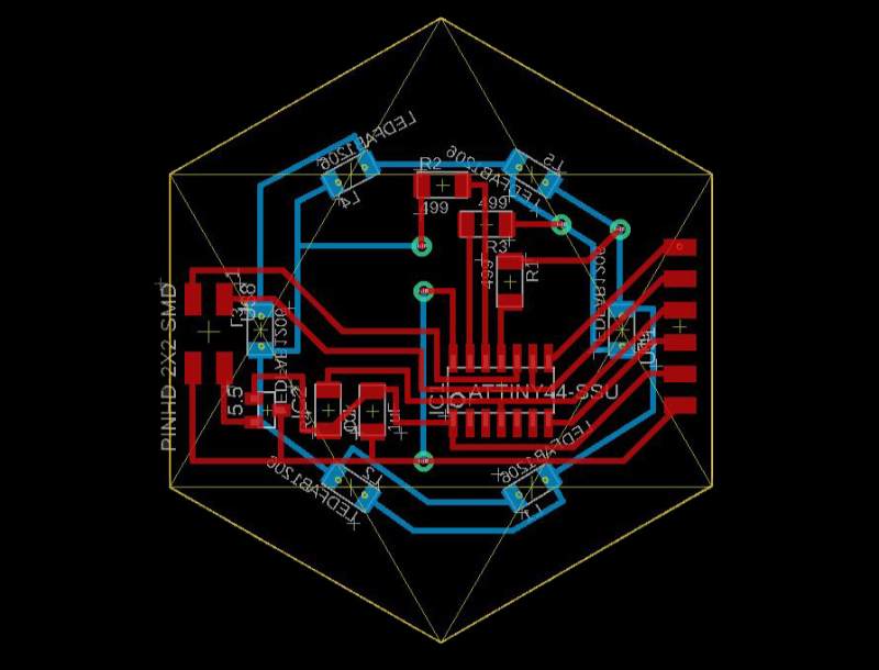
The first thing that I did is to design a pcb based on Charlie plexing I used the model gave by neil and also the explanation in this web page

Charlie plexing lets you control more LEDS than the Pins you have. The form it's like this:
N x (N-1)
This means that with 3 pins I can control 6 LEDs. But I have to connect them correctly. Using the three position that are possible for a LED: Output low, Output high and Input

Now that I know how to do it. After I have all the components I need to order all the components of my PCB inside the a hexagon with the same size and put the female headers in exact place of the male headers. I did it using the same dxf file that I used to put the LEDs in the resin piece.

After I imported it, it appeared in the screen and I started to order my components inside.


There were so much thing to put inside that I had to do two tricks. the first one was to use both sides of the pcb. We don't have sheets with copper in both faces so I'm going to mill each side separated and then glue them together.

The second trick was to change the six pin header that we usually use for programming for one that we use for FTDI. I did this because is smaller and I can sold the pins looking to the right instead than to the top.
Now it's time to mill the PCBs, i'll do it for separate and then connect them.


3d printing and plugged resin part.

I designed a 3d print to hide the PCB inside hold the resin part.
.jpg)
.jpg)
Programming

I download and edit a example code from the tutorial that i linked before. For some reason I had to expend some time at the hospital, so I didn't had time to sold and program the real PCB but I found a way to try my code before put it in the physic PCB: ThinkerCad
ThinkerCad it's a online program of Autodesk for 3d design and also for learning and emulate electronics. There aren't Atmel chips but it possible to load a Arduino 1 and a protoboard, Enough to try if the code is working or not.

The design can be view and modify here
The code can be seen in here
Soldering
I sold the board separate and then glued togheter and connect them using wires and tin
.jpg)
When everything was ok I tried the connection with the resin piece. It looks fine, anyway, I'm going to test the board with regular LEDs before connect the resin part to the board.
Testing and fixing problems
I burn the program in the microcontroller and the LEDS started to turn on and off but not as I would like, as you can see in the pictures some never turn on and some of them turn on at the same time..jpg)
.jpg)
I checked connections and everyting looks fine, I also checked my code which It was working fine too. So I suppossed that my LEDs wasn't in the correct position. This part is a little messy and after lost myself two or three times I drawn an sketch with the LEDs correct position.

After that I tried again and this time every one of them worked correctly :) first video show the turn on of the LEDs with a delay of 1000, second video shows a delay of 10.
During the process I thought that it would be cool to use this design to do something and, since I have six LEDs, it looks like a good idea to create a dice using a Tilt sensor and a battery. This would make it a tiny little final project because it will include all the elements included.
First thing that I need to do is adapt the board, because it wasn't designed for this sensor. My idea is to take of the 2x2 pin header and put there the tilt connector, I only need to cut some routes and put others together.
I think this drawing explains what I have to do: The tilt sensor needs to be connected to the VCC (5V) in one side and to the GND (with a 10k resistor in the middle) and to one pin, in this case I will use the one tha I was gonna use for TX and, also, I will disconnect the Rx and use it only to fix the tilt sensor.

Here you can see in three steps the process to finish it.
.jpg)
.jpg)
.jpg)
Programming
Now it's time for the code. I've been watching tutorials and examples to create a dice based in a button to create random parameters. I've been trying to mix that with my charlieplexing code but the results are not good yet.

For the Final project I design a second Output device with two buttons that will work as the capacitator that I will use in the final project. With the two buttons the Pcb is really full so I will connect some components in the bottom like I did in the other Output device board.

Here are the files ready to mill.
