NETWORKING AND COMMUNICATIONS. | WEEK 13

This week I got distracted with some things and I'm late with the assignment. To made things better I chose bluetooth instead a wire and thing become complicate for me...
The reason why I chose bluetooth it's my final project. I'm going to need a wireless system because two elements will by separate from 5 to 12 meters and I think that it's a huge distance for a wire.
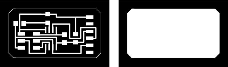
.jpg)
The modules that I'm going to use is the HC-05 and the HC-06. The first of them (HC-05) can be use as a slave or as a master, the second (HC-06) only as a slave. I made this drawing to understand better the different components and the difference between them. Visually HC-05 has more pins and a button
The goal for this week
I had a big goal for this week, I wanted to create the 3 boards that I need for my final project in this week and connect them. Many things to do from scratch.
I lost time trying to understand capacitive sensors and how I could adapt them to my poliuretane resin climb holders. I made some drawings about that.
.jpg)
Two boards will have a capacitive sensor, a led, a battery and a bluetooth. The third one it will receive data from the sensor and show a timer in a LCD screen, the board also includes a button, a battery, two LEDs and the master bluetooth device.
.jpg)
Testing. (debugging a no-assingment)
To test the bluetooth device I used my Fabduino. As an exercise I want to connect the bluetooth device and the LCD and send messages from my computer to the board.
It was my first time using a Protoboard so I started trying the resistors and the connections with a simple LED
.jpg)
I spent more time than I wanted doing this try, my FTDI with an outpower of 3.3V it wasn't working well and I ended using a regular one with a out power of 5V. It worked well but I spent the time worried about burn the ATmega
.jpg)
When I learned how to use the protoboard I based on an arduino diagram to connect a LCD.
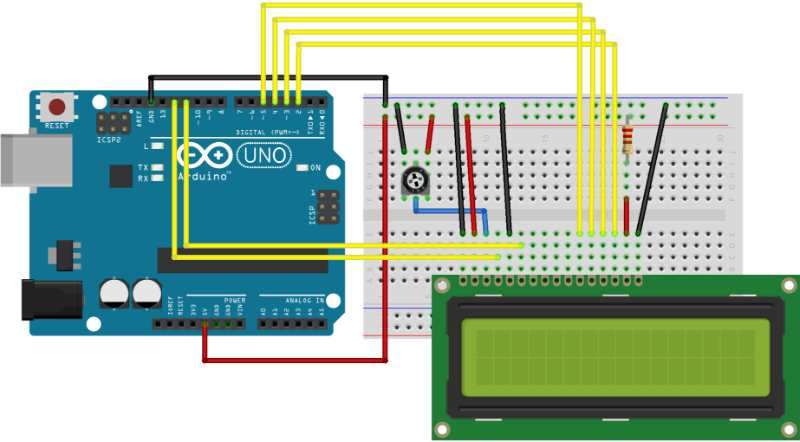
Although I did the connections well the screen doesn't look good the rectangles appeared and disappeared.
I've tried the example codes from arduino IDE but nothing appeared in the screen.
I supposed that the problem could be the screen so I changed the connections for the LCD screen from Fab's inventory. It didn't worked. Again I had problems with the screen
.jpg)
With all this problems I finally didn't even the assignment for this week :(
.jpg)
My final project has two different boards, one for the input (a photoresistor) and another one for the outputs ( six Neopixel and one stepmotor). I need to connect them so this is perfect to finish my networking assignment.
Photoresisitorboard
.jpg)
.jpg)
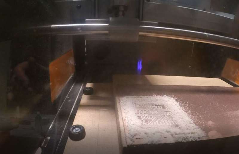
Here is the first board that I made, the small one with one Input, a phototransistor that can measure the quantity of light. I Mill it and then sold all the components. before try the networking I used serial to see i the computer could read the values correctly. The code was very simple:
.jpg)
But It wasn't working well, I checked connections and everything was working well, at some point I've found that the computer could read everything well at 300bps, which is odd because I define the speed at 9600bps. I didn't know why this was happenning but I divide 9600 / 300 and the number is 8. The only thing with an 8 that I can think about it's the internal clock (8Mhz) but I can understand why this is happening, I've change the speed to 9600 x 8 = 76.800 and then I could read the values at 9600bps. Which is ok because it's a way to make it work but I'm still worried about something that it's happening without my understanding.
Solution: Two hours later Rodrigo, one of my classmates, has the same problem and we understand why. We didn't burn the bootloader before burn the program and that was the reason why the board wasn't working well. Not I can go to the next board.
Helioduino board
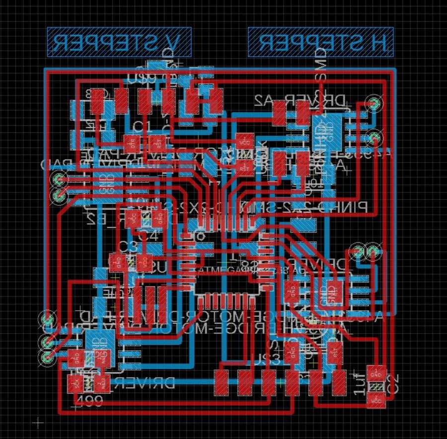
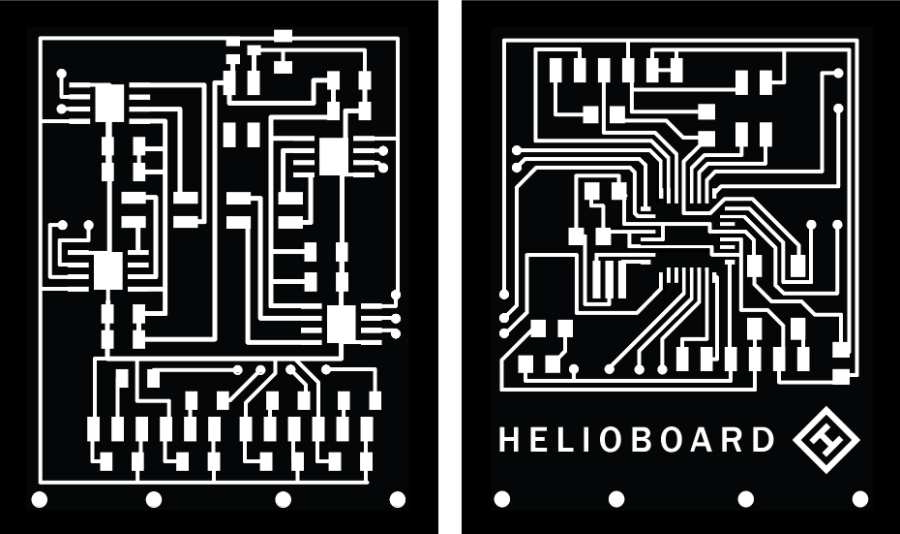
The helioduino is the most complicate board that i have ever done. It has to sides and it's prepared to move two bipolar stepmotors, and control 6 NEOpixels, I also left some space to add a button and it can be program without programmer, just using the FTDI cable. If you want more details I explain everything better in the the project develpment section. There you can see how I tested connections many times and do some changes to make it worked (at some point I was very sure that I'll never working). When I get it work to move a step motor it was time to try to do it using my phototransistor.
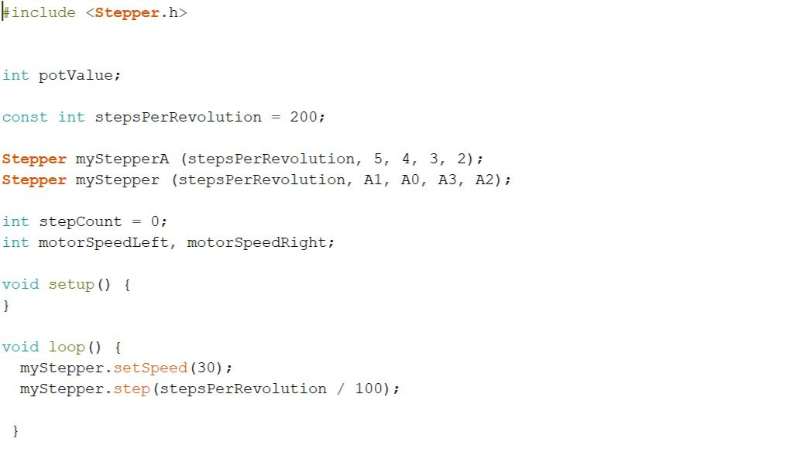
Here is the code that I used to try that my helioduino board works.
Networking
To connect both boards I used Serial library. Phototransistor board is the emitter and sends values to the Helioduino board that changes the speed of the stepper. Here is the code for the Phototransistor board
Instead of use the line:
mySerial.print(s);
I changed print by write, because the other board can't read print
mySerial.write(s);
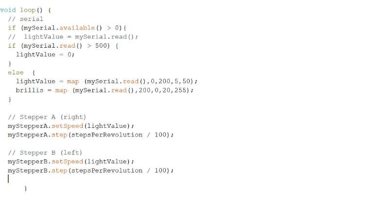
In the helioduino board I mapped the value from the photoresistor so it adjust to the range of a stepper (from 0 to 100)
Here is the code to read values from the phototransistor board
The whole code can be found in my documentation or here:
Results
Here is a hero shot of the stepper motor responding to the signal of th photransistor.
After It worked with the stepper I tried also with the LEDS
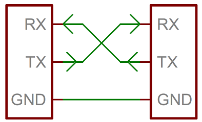
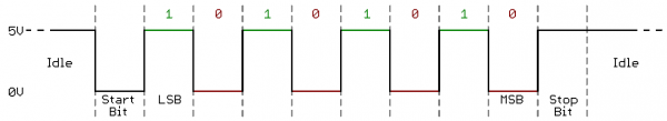
The serial communications that I used in the final project works but it's not enough to create a network, as my global instructor said I need an adress for each device if I want to connect more than two boards. I read this tutorials to unsderstand better what is serial communication. this from sparkfun it's kind of interesting, basically explains how the wires must be connect, it is necessary to use three wires, (RX, TX, and GROUND), the two of them for communication must be crossed (the transmiter from one board is the receiver in the other one). They also explain communication based on TTL protocol. It based on bits to send the message.
The other tutorial that I followed is this one that explains how to connect two or more arduinos together, we don't like arduino, but I think that the dynamic it's the same. In this case they use the I2C protocol or "Inter-Integrated Circuit. It need three wires, one send the clock signal (SCL), the second one is to send the data (SDA) and the third one is the ground, all the boards needs to share the same ground.
Trying with my own boards.
For this exercise I chose two boards that I have at home, because my final project it's still at the fablab. I chose my sonar board and the RGb board that I did during the first week of proyect development.
.jpg)
In arduino IDE I modified the code to include the serial and the give a specific ID to the board that I wanted to connect to. The code is designed to change the color of the light when a object it's too close to the sonar.
.JPG)
The picture looks very small so both codes can be seen better here
Here is the video when finally I got both boards together and they worked
The codes can be consulted in the documentation or here
RBG board Sonar boards