
PROJECT DEVELOPMENT.
Well, here we are. After 20 long and intense weeks it's time for the final project development. I decided to do (or at least try) a daily ordered documentation and that's why I have created this webpage.
31/05/2019. Electronics design and programming.
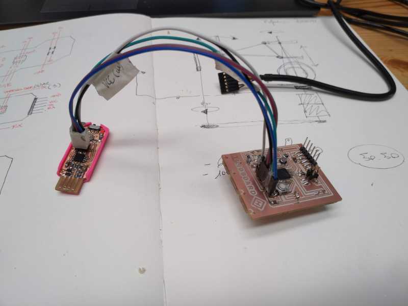
I'm worried about my electronics and specially my programming habilities, so my first step with this final project is design program and connect three basic boards that will be the prototype for my real final board.
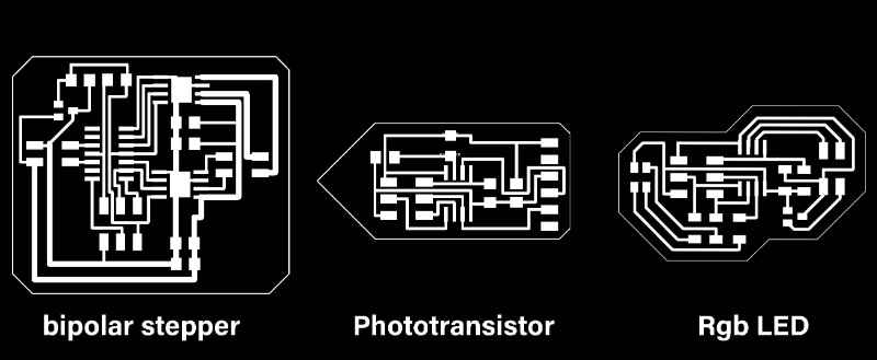
My final project has light and movement made by a light color sensor. I dont' have the light color sensor but I can try with the photransistor to make something and comunicate the three boards between each other and see what happens. So I design and mill a first board with an RGB, a second board with a phototransistor and a third one with a step motor.
These are very basic design based on Neil's boards, I'm not worried about complexity because what I want to know it's if the works. This is something that I should have do in the input / output devices week but I wans't decided my project then. Here is the Pngs ready to put into fab modules. Here they are
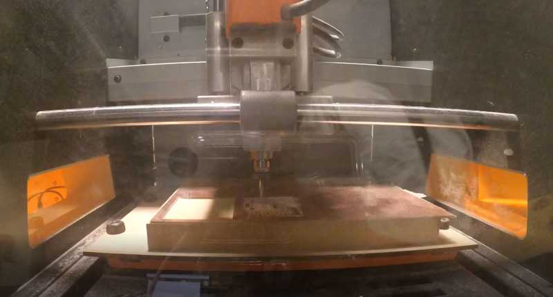
It's time to mill them. After some time without do it I've lost practice and the machine is not in it best way so I have some problems with the routing, specially in the phototransistor, RGB has a white area to0 profound and the copper routes in the phototransistor where more than slim. Anyway, It was enough to sold components and test them.
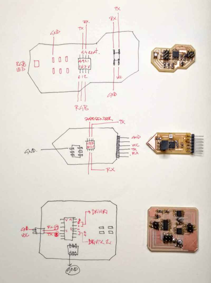
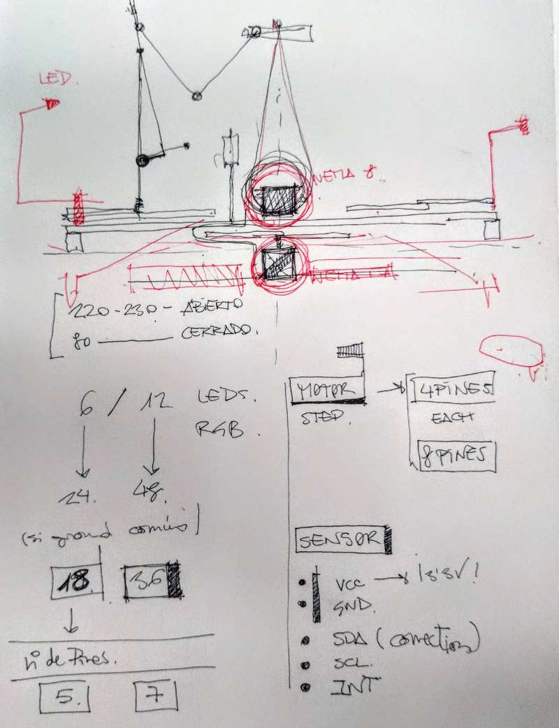
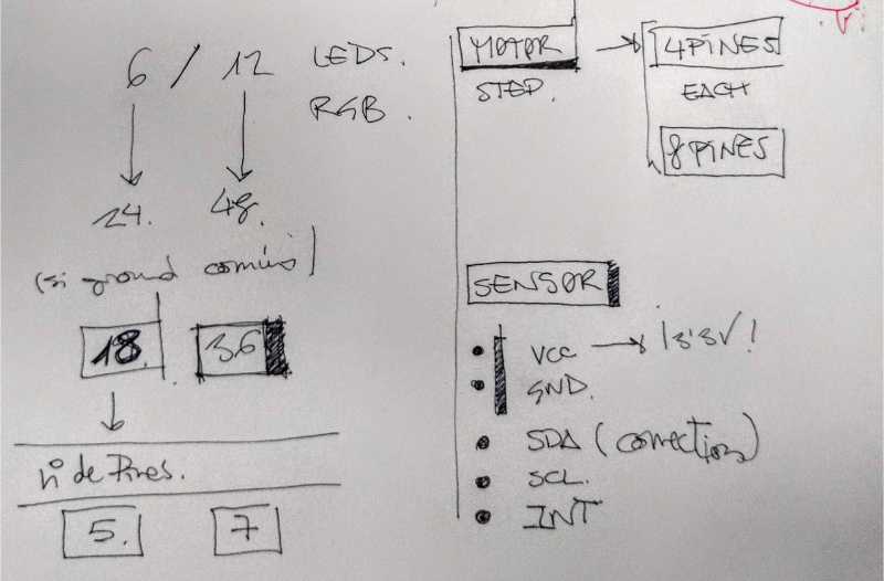
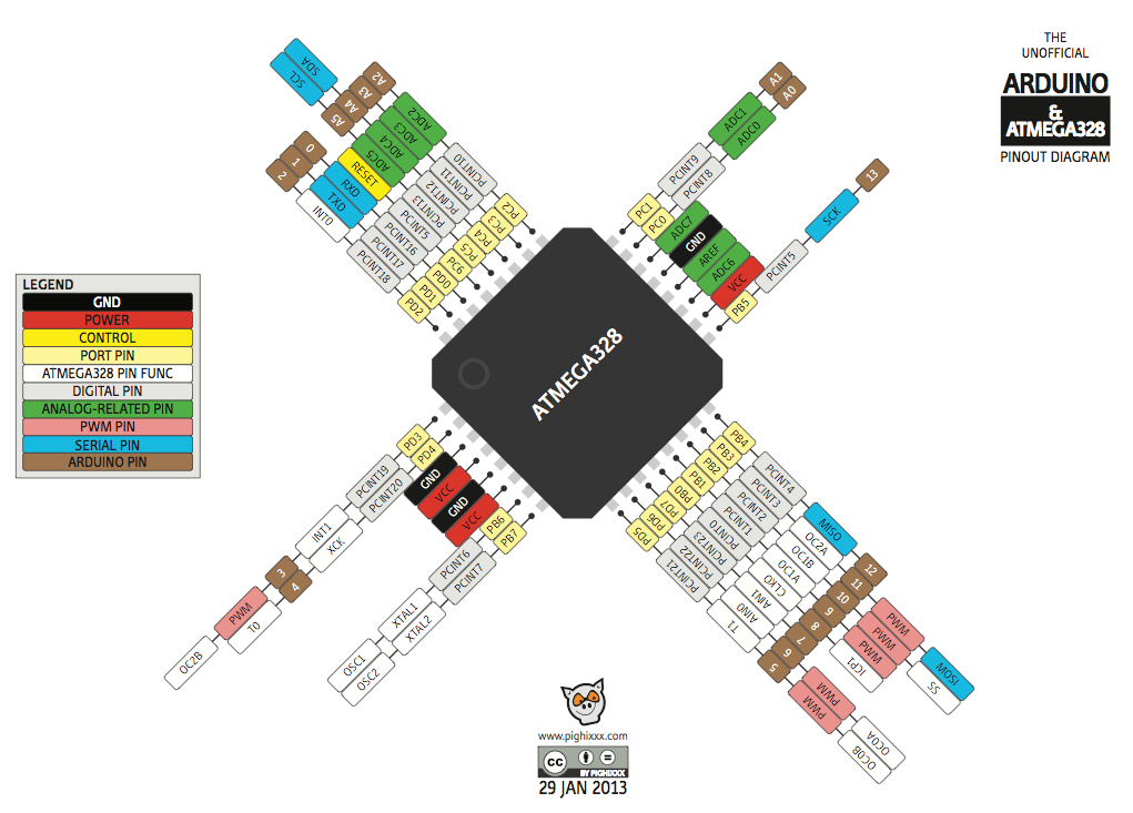
I usually get lost with the pins and have many problems because I'm not using the correct ones so I create this drawings to have everything close to me and well documented.
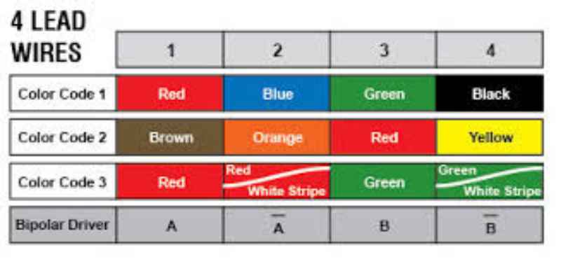
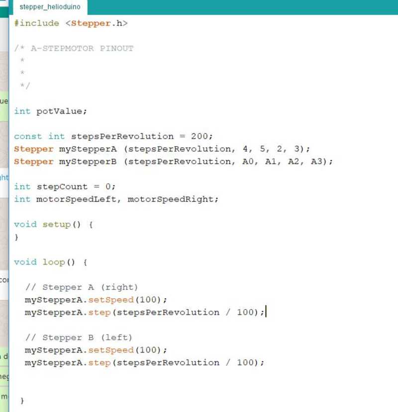
Stepper
First problem with the stepper is the understand what are the correct wores for each pin, I look for the pinout of a stepper and I found this diagram, which works perfectly.
Not I prepera a very basic code, just enough to make the stepper move with a constant speed
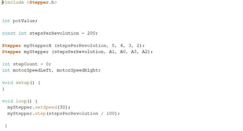
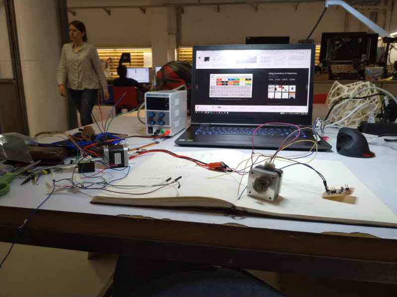
the code work fine and the stepper moves ok as you can see in this video.
RGB
I did the same for the RGB, I'm not sure how I'm going to use this LEDs but this board It's a good Start. Again, I'm using a basic code just to see what happens.
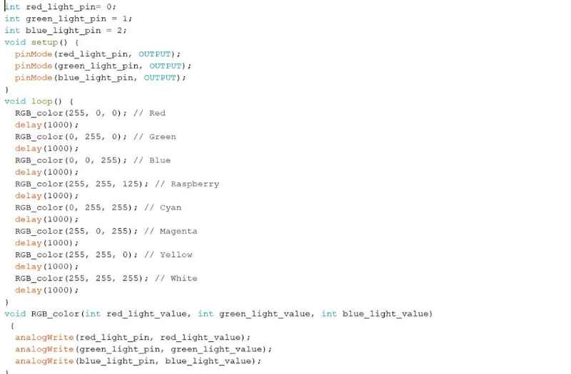
The code works fine as you can see in this video
phototransistor
I left the photransistor for the end I didn't have time to finish it my test. I hope to do it in a following day.
1/06/2019. Mechanical design
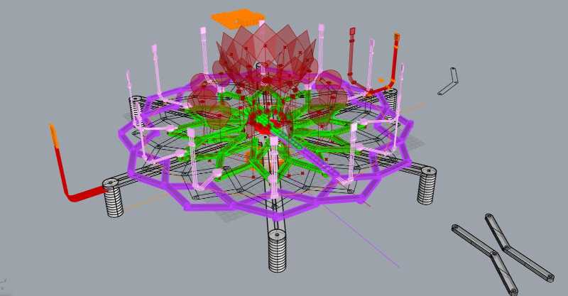
It's weekend I want to spend it designing and trying the structure for my final project. I have a basic 3d model made with Rhinoceros and grasshopper that I started a few weeks ago. My idea is to improve this model to defines sizes and distances and then create a physical prototype with MDF.
Computer aided design (Rhinoceros + Grasshopper)
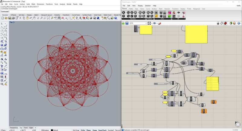
I have some problems at the start with the grasshopper code, I usually get lost when I have to connect diferrent list, but after some tries and error I got a good result
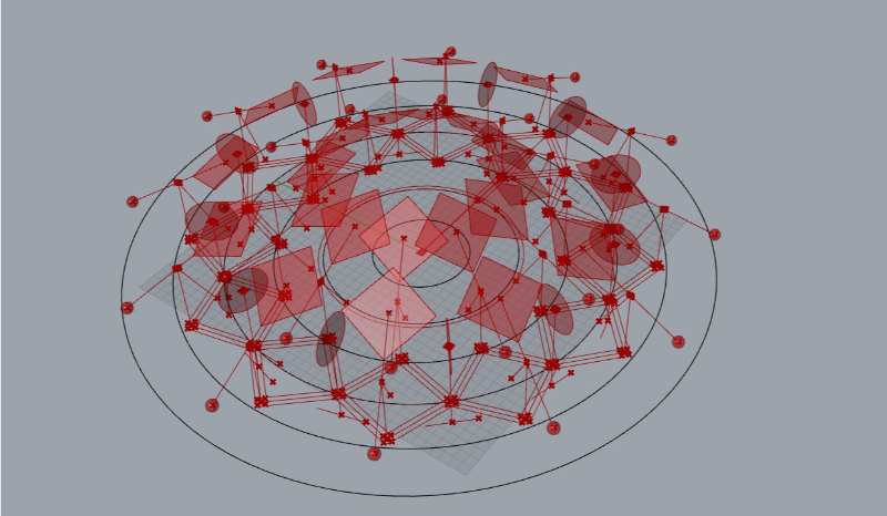
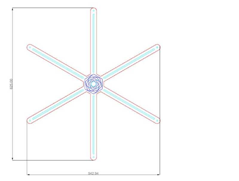
Now I need to make "physic" this structure by giving it a more precise size to each element in the structure. But here you can see a small animation of what I want to get
Maybe this is too ambitious because I'm not sure of can I connect the three movement or control them whit the stepmotor. My idea is to focus in one of them and, if I have time improve it in a future spiral.
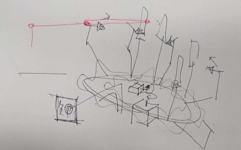
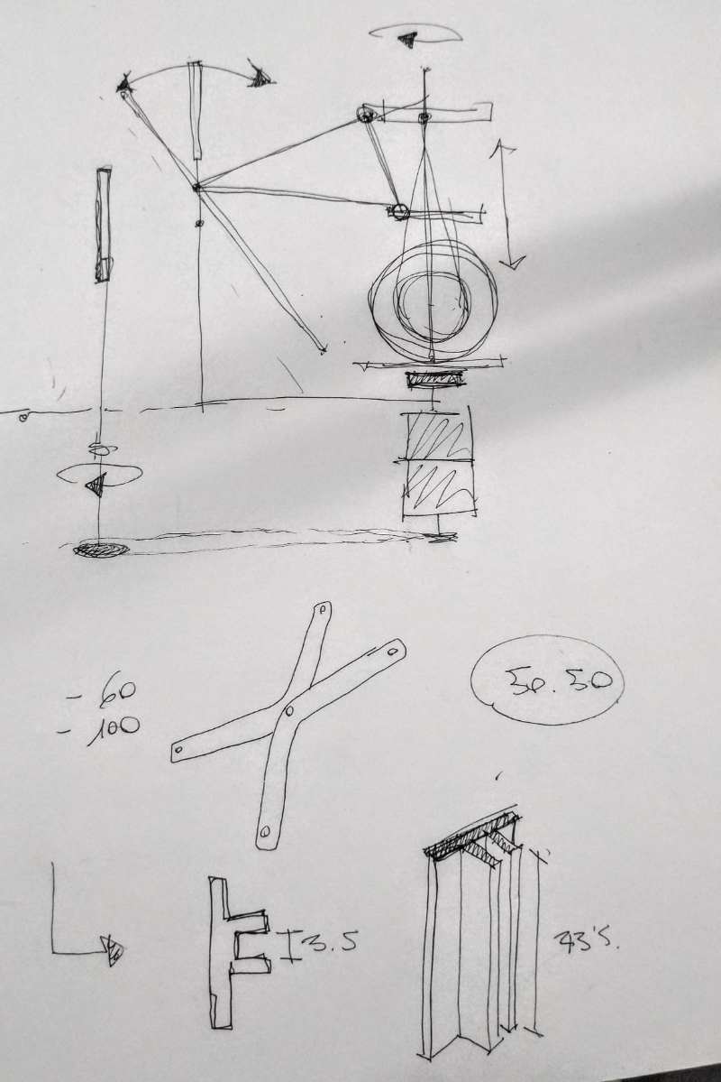
I spent the rest of the afternoon making my project "take ground" and redesigning everything, I like to think with pencil and paper at the same time that I'm working in the computer. Here are some scketches of the afternoon, as you see i'm concern about the movement.
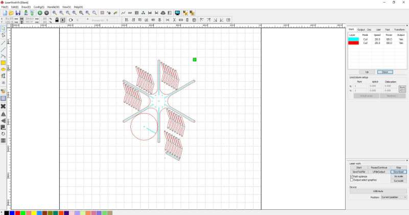
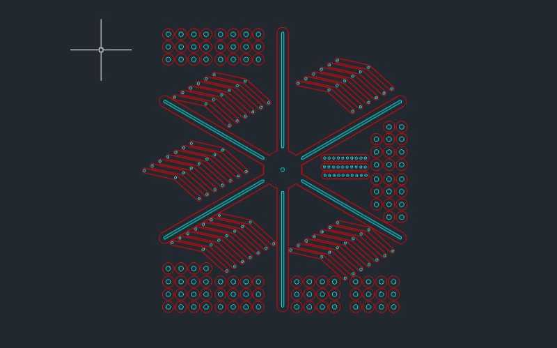
By the end of the day I have prepared a file to lasercut with some pieces for the first prototype, tomorrow I'll be focused only in this because I want to have the mechanism ready for monday
2/06/2019. First prototype
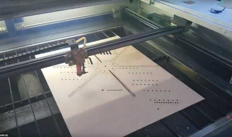
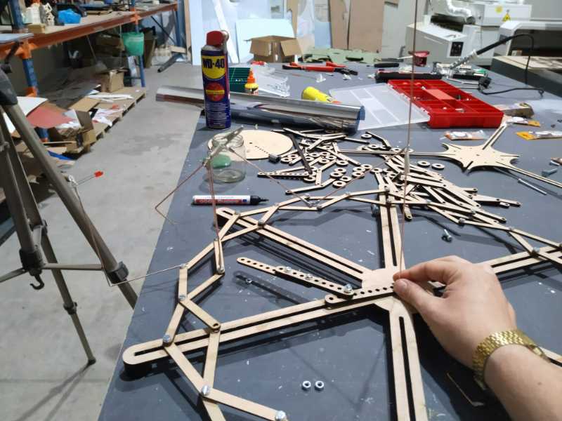
I cut a first set of parts in MDF to test the movement that works so well in my computer. Guess what, reality is not the same. i could cut them on Monday because I worked in a lasercut company and they let me use the factory in the weekends.
.jpg)
.jpg)
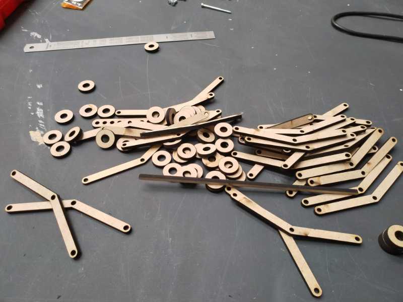
I bought some screws and i'm using it to create the whole zig-zag circle. With some time I get it but I find my first mistake: If I thighten the bolts the movement becomes imposible and if they are loosely the fall of the structure. Anyway I can mount every thing and test.
.jpg)
It's really hard to move the structure, I think that it's because of the friction of the MDF, the structure is very thin (I have use 3mm MDF) and is curve. I think that it would work better if I use 5mm MDF and reinforce the structure in some points. Anyway, i test the final element of my design: a wheel that will be connected to the motor to move everything.
It was a good idea to mount everything together, now I feel that the wheel is very unconfortable and It's not really necessary, mi idea was to use it to put more stuff in the top but now I understand that the top it's the only place to the connection between the wheel and the flower structure ( in the bottom it cross with the axis of the motor)
Redesign and second prototype.
With my new expertise in mechanism I made some modifications for the second set which are:
- thicker parts of 5mm MDF
- Reinforcements to make the structure more solid and avoid curvature.
- Change the central wheel for some linear parts with different wholes to try different appertures of the flower mechanism.
.jpg)
.jpg)
With the new part I have a stronger structure and a better mechanism but the problem of friction was still there. I was starting to worry very much when I finally decided to try with give some wax and some oil to the structure.
It worked!
Upper structure. Time for the copper rods.
My idea for the upper structure is to use copper rods sold and fold, connected to the structure using electronic elements. I started with the basics.
.jpg)
.jpg)
The "V" structure is design to sustain a two rods crossed that can make a pendulum movement. Here is the first V finished
.jpg)
And here are some details of the connections
.jpg)
.jpg)
.jpg)
With this elements I created a basic section of the structure, if this works the rest are as easy as copy this one twelve times.
My conclusion is that it's possible to do but I really have to think about how can be done and I don't know if I'm going to have time to do it. Here is the video of my try.
Conclusions of the day
Well, it's the end of the weekend and I'm not very happy, I wanted to have the mechanical finished or very closed to the final idea and it's not. At this moment I have to think how can I simplify my project, because I have to work in the mornings and I don't have so much time to spend.
3/06/2019. My head is a mess. Thinking about the electronics
I want to redesign the electronics for the final project but I don't know how many boards and how to put them together. At this moment my project is inconsistent and I'm scared. I spent most of the afternoon talking with Marta and counting pins.
I start to redesign the same fabduino that I did in the week of input devices bad didn't finished. I need to clarify my ideas.
4/06/2019. Electronics design
After yesterday today my ideas are clare, I'm going to use two boards, the main one will be focused in the outputs of my final project (two stepper motors and six neopixel), the secundary one will be focused in the input devices, a phototransistor and a color light sensor that I would like to incclude if I have time. The problem is that is a model from Sparkfun and I don't know if I would have it on time.
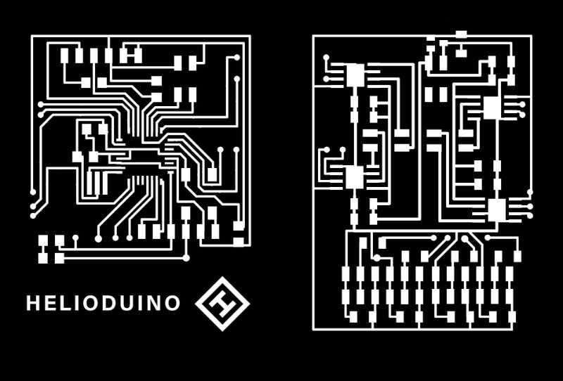
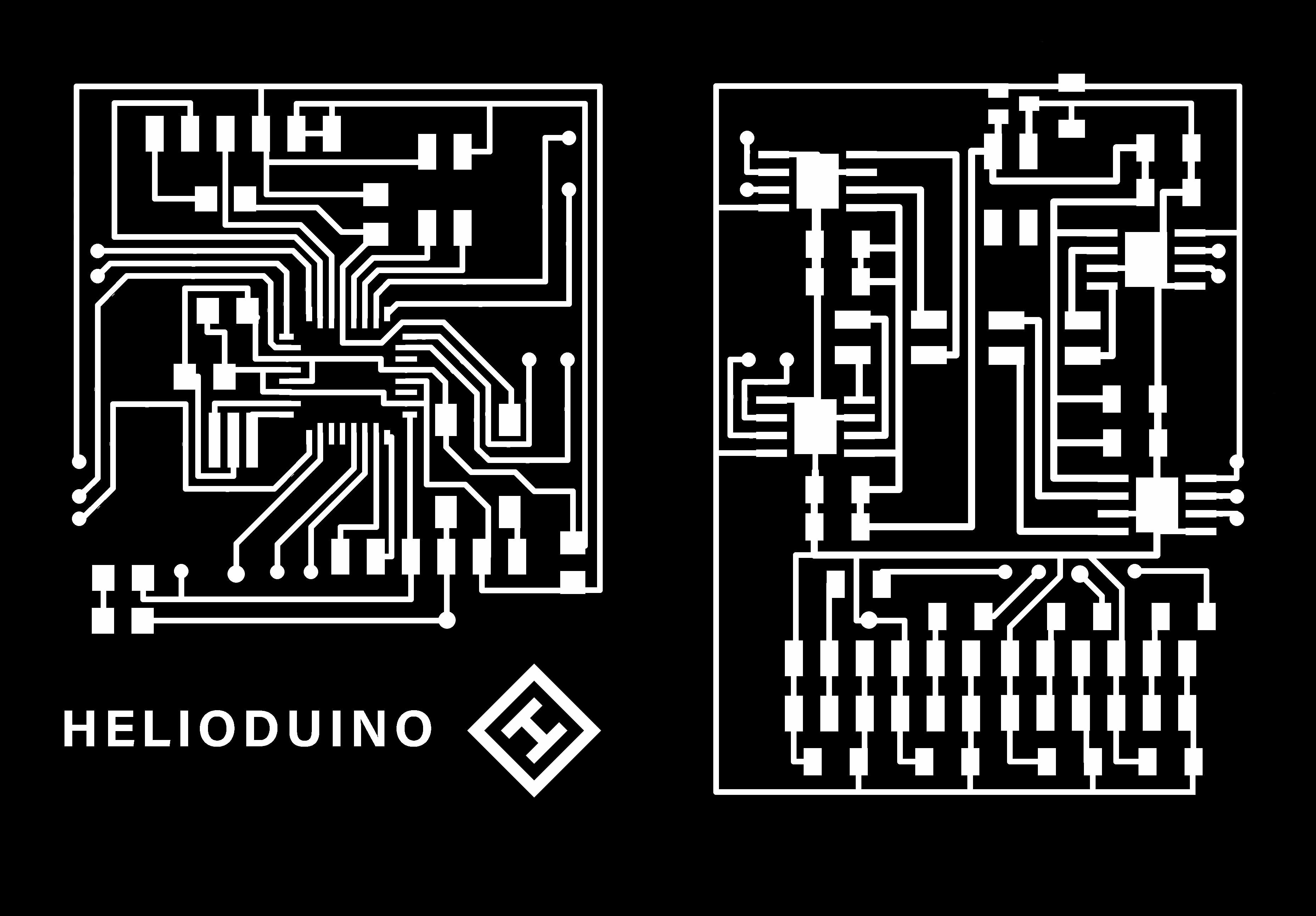
My goal for today is design my own version of a fabduino, The HELIODUINO.
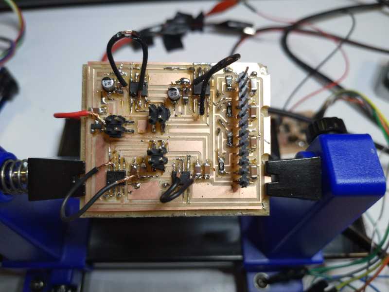
The base for this board is a AtMEGAP, I'm not scared about sold it because I did it in the past but too much pins are a lot to worry about so I print this picture and go very slowly
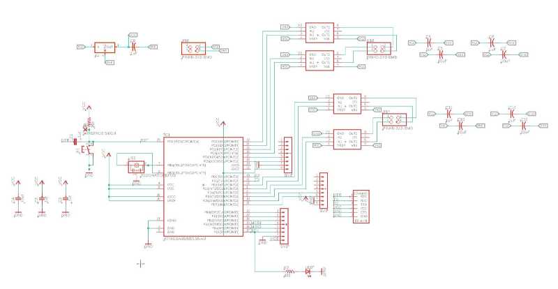
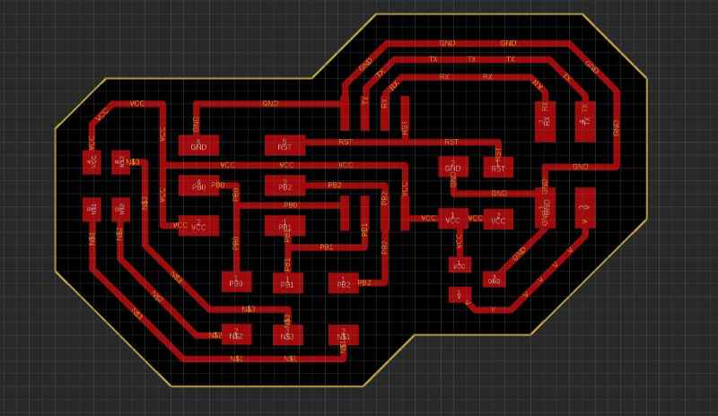
I didn't started from scratch. On contrary I used the schematic of the fabduino and start to change everything from there. At some point I felt that it was going to be very difficult to put everything where I wanted to be if I didn't use one of the faces of the board so, as I did with my charlieplexing board (output devices week) I flip all the components focused on the outputs and left one side almost with the basic elements of the fabduino, although I took it of everything that it wasn't necessary for me. In the other side I start to order the drivers for the step motor, and the pin out for the Neopixel LEDs.
I cut a first set of parts in MDF to test the movement that works so well in my computer. Guess what, reality is not the same. i could cut them on Monday because I worked in a lasercut company and they let me use the factory in the weekends.
Here is the result of the whoel thing, looks cool and scary but wait, if you see layer by layer is something much more simple.
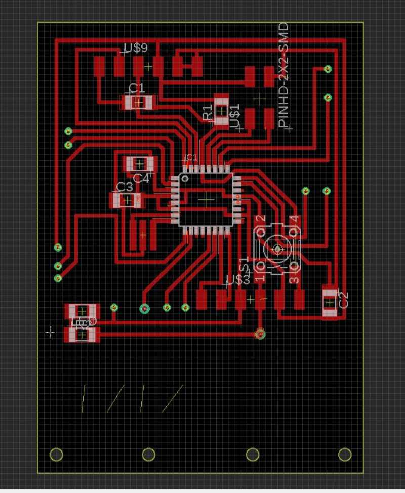
Here is the top layer with the Atmega, the LED of the fabduino that I left to check my board and the button which is something very useful to reset the board if my motors start to do odd things.
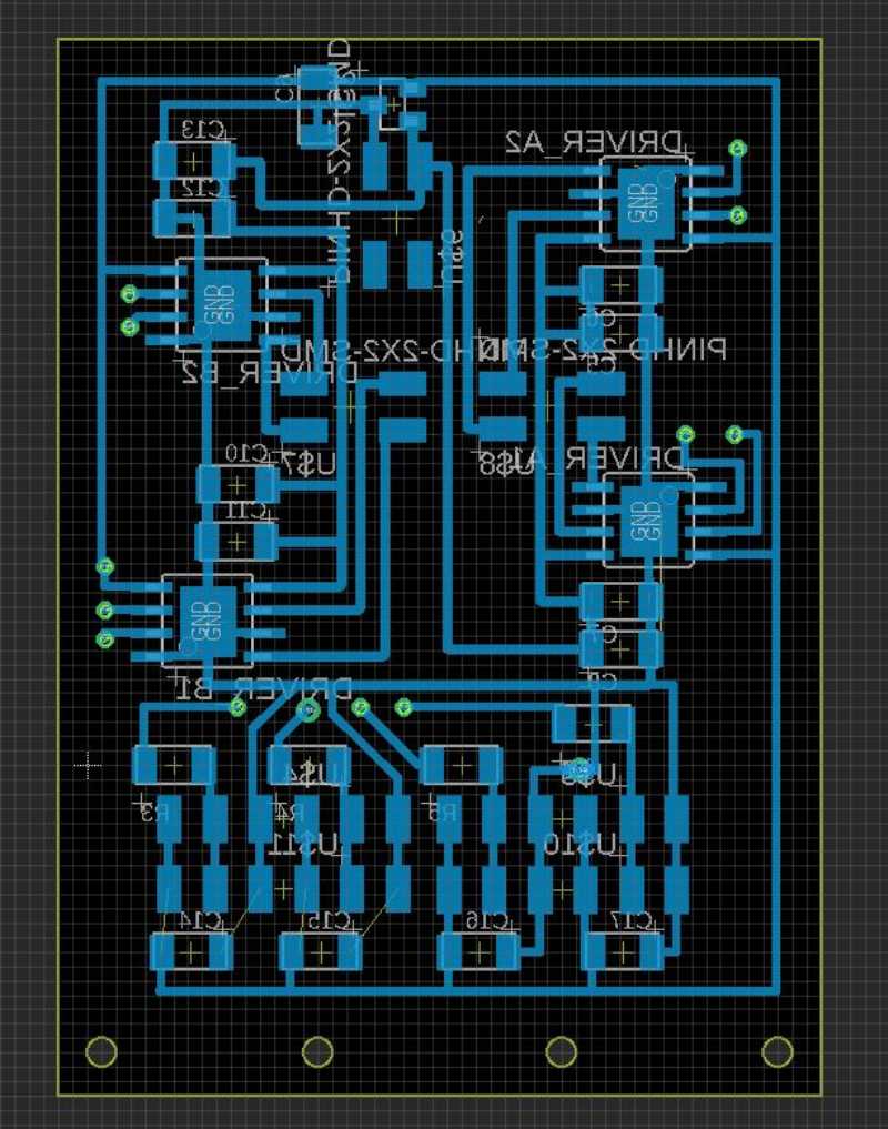
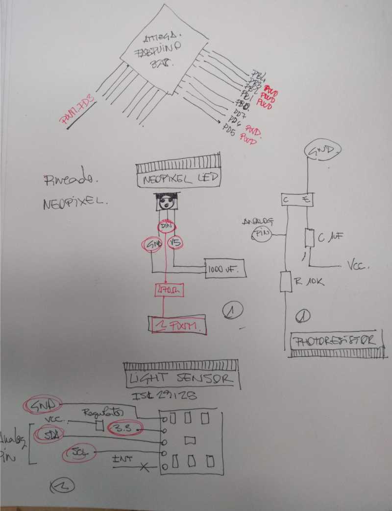
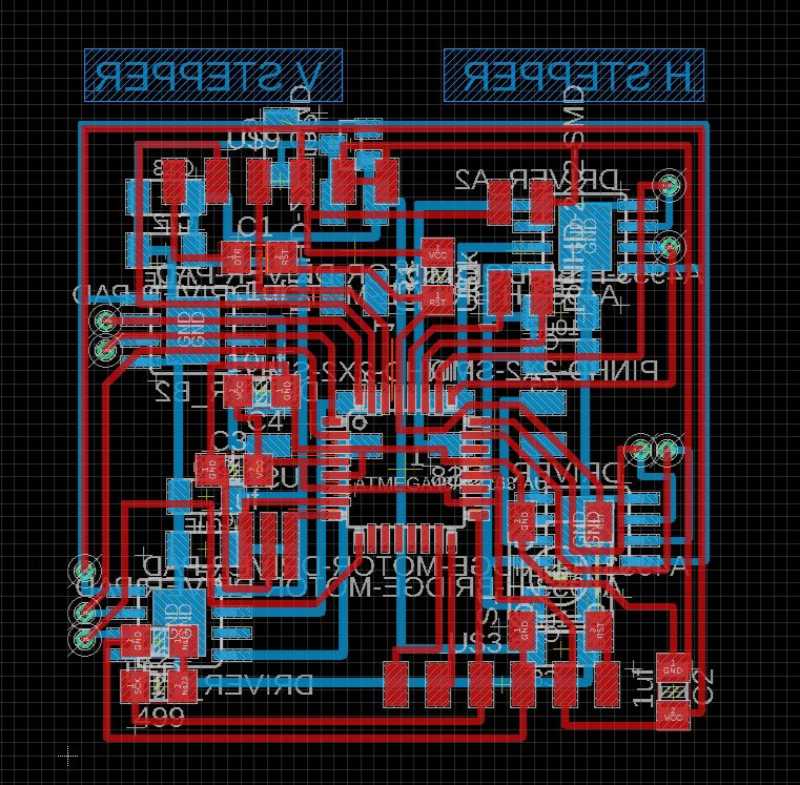
this is the bottom part, with the pin out for two bipolar step motors, and four lines of neopixels (in the bottom. Also, there is the pinout for the 12V power. I based in this schem for the protections of the neopixels and in neils boards for the schem of the step motor.
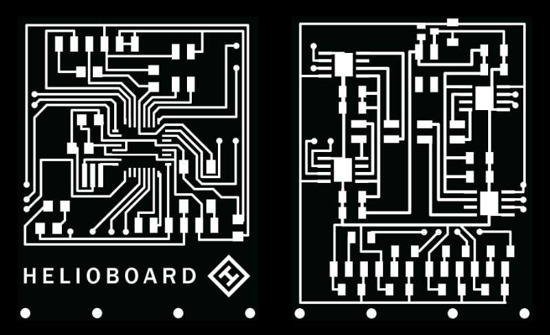
Now I just added the name and my logo in photoshop so the png is ready to be mill.
Conclusions of the day
I'm very happy with my board and I feel better about my chances to finish the project. Anyway I'm worried about the time that my job left me this week to finish.
5/06/2019. Electronic design (2)
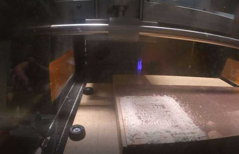
I started the day (or the afternoon) milling the Helioduino and while is milling I started to design the sensor board.
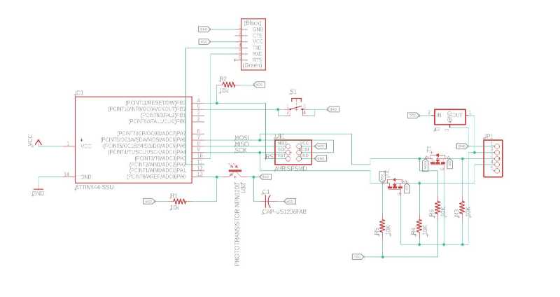
I prepared the schematic with a Attiny44 and then, when I was going to start with the board my instrutor suggest me to test in arduino IDE if the Attiny44 had enough space for all the libraries (the sparkfun library for the light sensor and for the serial to comunicate this board with the main one. So I stopped an try that.
The rgb sensor
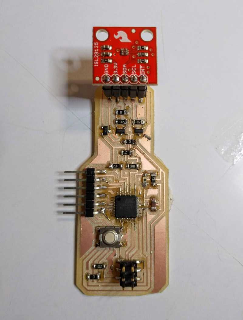
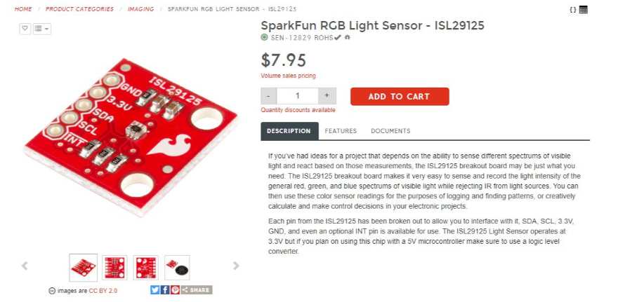
When I looked for a sensor that can read color I found that most of them are to read color, not the color of light. This is more specific and difficult, but I've found the ISL29125 too tiny to sold by hand, thankfully Sparkfun sells one prepared

The good news about it are that sparkfun has many information, tutorials and a example code to see the hardware and the software to use it. I didn't notice about the library and at this point of the week I did the probe that Marta (my instructor) told me.
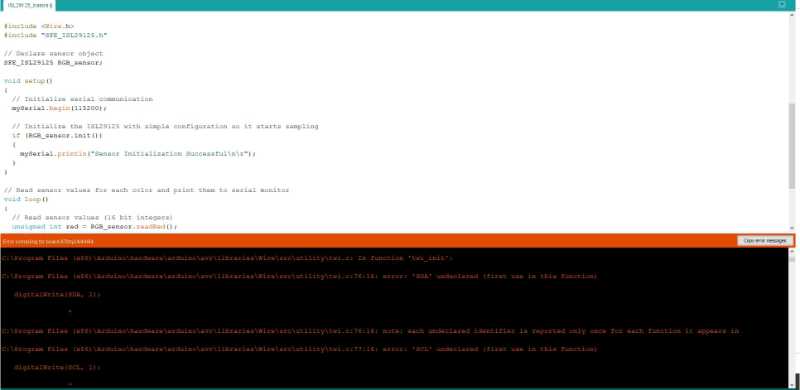
...and here is a huge problem. The program is too big for the Attiny44. I need to think about an alternative. The Attiny 84 could be an alternative but we don't have any one at the moment in the Fablab so I'm going to have to use another AtMega, maybe too much but it's what I have here right now. Even more I've found a image explaining how to connect the module to an arduino and, since the sensor is powered at 3.3v I'm gonna need to use a logical converter... which I don't have...
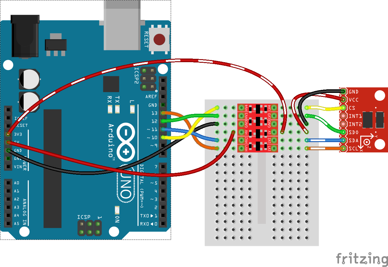
Anyway, this shouldn't be a problem, Neil has prepared me for this moment, I checked the logical converter board of Sparkfun BOB 12009 It's possible to download the eagle files and see the kind of components that they are using
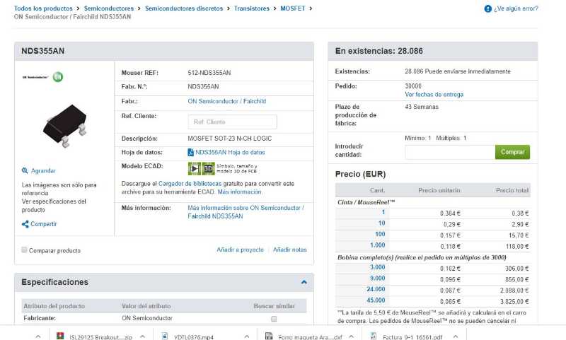
A mosfet converter for N-channel, I looked in the inventory of our lab and we don't have the one with the same voltage and amperage but, one of my classmates explain me that the important par it's the channel, ok, I can do this.
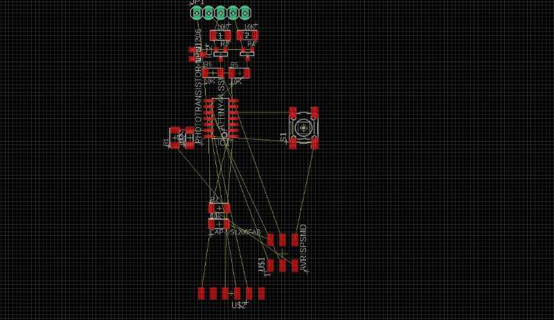
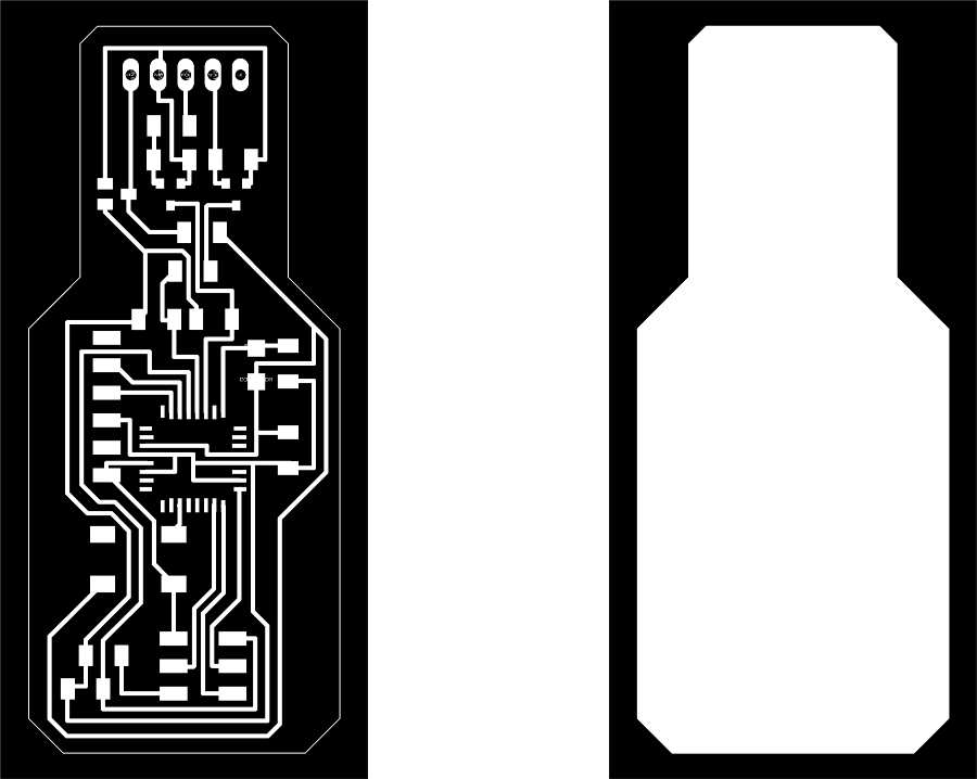
I donwload the board plans from sparkfun and rebuild my schematic and my board.
After some changes and 1 hour of hard work here is my final board for the sensor, it looks great, I think, but i'm worried about the rgb light sensor, so it's include a phototransistor, just in case.

Results
On the other side the milling of the board has been a nightmare, the milling machine is not in it's best moment. Tomorrow I want change the mdf base board and calibrate the machine because the result of the helioboard it's acceptable but not very good, not even close to a good result.
.jpg)
.jpg)
Conclusions of the day
I'm proud of my electronic design, it's something that a few months ago I don't even thought that I could do. In the other hand the clock it's ticking and I'm founding problems everywhere. The milling machine is working worst than ever and I'm founding problems that I didn't spect.
06/06/2019. review
This week is a bad week, we know that from the begining but with the stuff at work and the final project, sometimes look like something made with bad luck. Today is the day for the review, with Neil watching and all the stuff and... guess what, when he ask for me I had nothing uploaded and It was like those dream when you are naked in the middle of the class. Really, it's like hear a building fall. You can see it in this video. Minute 1:16:00
Fab-20190606B_Review18: invention, intellectual property, and income from Academany on Vimeo.
After something like that I was really worried, I got back to the lab and try to mill something, preprare something, everything at the same time... Bad day. At least, since today I have holydays and I can fully focus on the final project. I want to rest today and tomorrow we will see what happens.
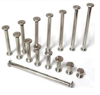
Some good news, I have the materials for my final project, the book screws, that I hope won't never fall while the mechanis is moving and the PVC flexible mirror for the top structure that I hope that it's possible to cut in the vynil machine. :) oh! And also my neopixel LEDs
07/06/2019. Solding and Milling
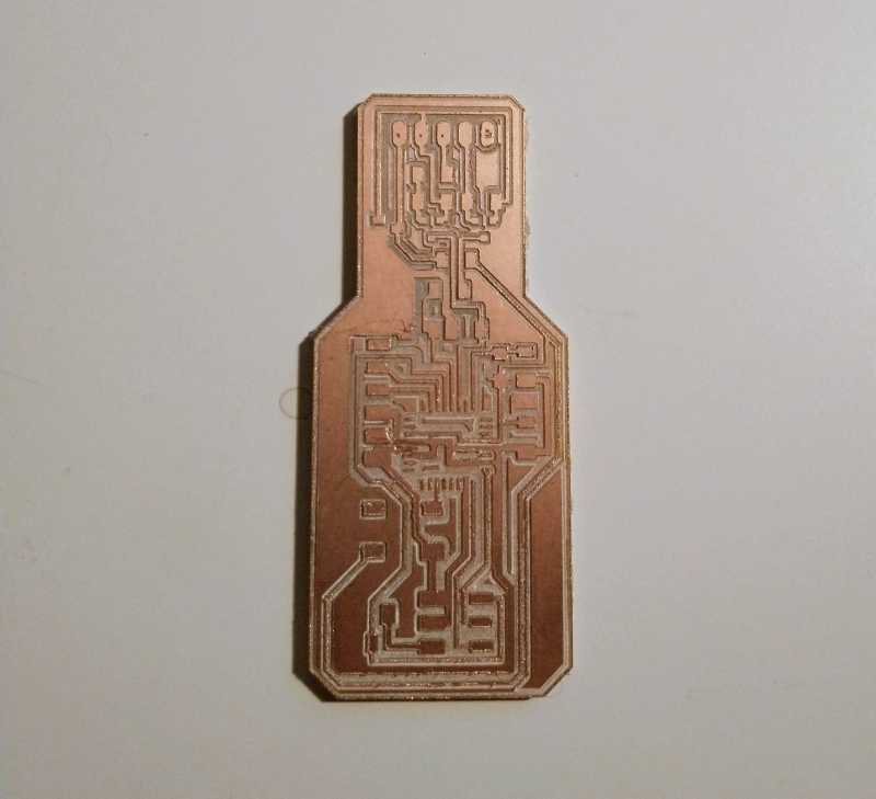
I woke up early and went to the Fablab to mill my last boards, tomorrow it's saturday I can't mill anything until monday, but I need my boards working before that. I have to mill three thing, the back part of the helioduino (the first time I did it I forgot to mirrored and now I can't use it, even with wires because traces drivers are not simetrical, the final version of the sensor board and the tiny phototransistor board (the one I made in day zero but with better routes, just in case). I calibrate the board and change the drill bit to ensure better result than in previous days.
First impression shows better results than in previous days. take care of your equipment, that's my advice.
.jpg)
The phototransistor board looks very good ( I only did a minor change and redraw the border to take out the triangular edge)
.jpg)
The Helioduino back part from the helioduino is fine, some problems with the border but the traces are good and looks good after I drilled the pads to the other side, so I can connect them. great!
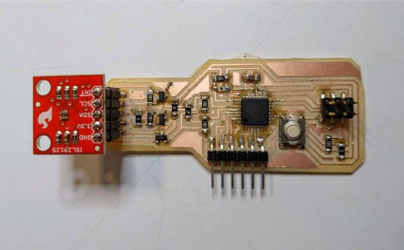
Sensor board had an error very extrange and the file forgot about one of the pads, so I had to mill it again. Anyway, at this point I have to focus on the elements that I have. Yesterday I decided to simplify and use only one motor and the phototransistor, I left the other motor and the RGB light sensor for the final days or as an extra after the final project.
I spent the rest of the day solding the Helioduino board, it takes more than I thought but if you think about it they are two boards connected with many components each of them, and after everything is sold I have to connect them together and check the connections of everything. I made timelaps to shor the hole process here it is.
At the end this is the result
.jpg)
.jpg)
I also have time to sold the phototransistor one
.jpg)
Now I'm ready for the weekend. Tomorrow it's time for programming.
07/06/2019. Programming and fabricating.
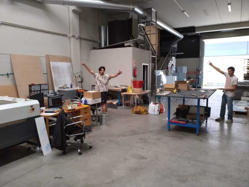
Saturday. five days to go and many many things to do. For this weekend we make a hackaton. Two of my classmates came to my home because we decided to work together in my job factory, since the Fablab can open during the weekend we think that it's the best options for us, it will make us be focused and work more. Even more, we can help each other to solve our doubts. The first thing that I need to do is put my sensor to work, I've made some tries with the stepper and the rgbs but the input it's still in the air.
I burned this code in the board, just a serial to read values on my computer. The code looks good and compile good but when I connect to the computer and put 9600bps this is what I got... noise...
Then I checked the code, ask to my instructor, ask to my classmates... not working. It's the saturday before the presentation and my board is not working OMG. Then I tried to see if I can read the values with another speed and... it works! If I select 1200bps in the serial monitor everyting seems to be fine. that's odd. Very odd but it works and as the first rulo of electronics says if it works don't touch it.
Some time later rodrigo has the same problem and we understand why: We didn't burn the booutloader before burn the program! After we did that the speed seems to be correct.
Time for the big board
Now I want to test the helioduinoboard and see what happens, if everything goes fine then I would only need to worry about the networking communication.
This is the basic code to use in the board. I burn the bootloader using the programmer, after that it's possible to programm the board directly using the ftdi wire and without using the programmer.
I do that and then try the stepmotor code. Nothing happens, the board doesn't even show amperage at all. Umm surely this is something about connections. I tried again. This time If I up the voltage it show a very small amperage but nothing moves.
.jpg)
I checked the motor with the other board the one that I tried the first day, the stepmotor works odd but works and the code is the same.
.jpg)
.jpg)
I check voltage in the drivers to see whats wrong values are not the same in both boards, I checked connections again and check the schematic again. I don't understand what happening. I talked with my classmates and seems bad. I test the components see neils board, review everything over and over nothing works. I'm worried because the stepper it's a nema 17 for 2.5 Amps, thats a lot. That could be the problem and in someway it is, because the movement in the other board it's odd and rare but it's has to be something else...
At some point I decided that It's better to continue with another task than get stuck there. I need to put some part to print if I want to do have them for tomorrow.
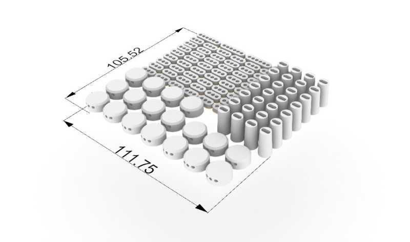
Remodelling my model
I start to add final parts to the abstract model that I made last weekend. This time parts have an specific size and funcion. The parts that I wan to print are the orane ones, connectors for my copper rods and other special parts as the wheel that connects the arm for movement with the step motor, the supports for the structure...
The code is now a very big pulp with many parts and elements, something very complex so I have to separete in groups and use panel to identify each part of it.
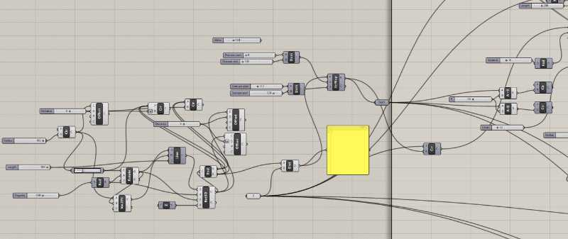
here is the connection with the step motor and the part that move everything.
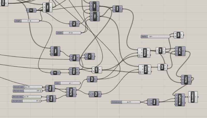
here is the main movement (the flower one based on the last image code.
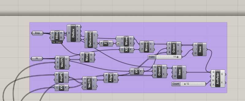
Here is the solid elements from rhino that I parametrice to move with the structure.
From all the structure I select those parts that I need to print to connect different elements, structure with mechanism, mechanisim with copper rods...
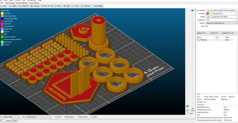
I used scil3r to prepare the parts for printing 10 hours, at this point of the day sounds like a call to go to sleep. So I consider the day finished after this point.
Conclusions of the day
I'm worried about the helioduino and the drivers, but I hope that tomorrow I will find a solution, at the end the board is working, I can program the LED and recieves current. It was a good idea to get back to the model, After that I was relaxed and felt more positive, because fabrication let you see something real, programming it's more abstract.
08/06/2019. Fabricating and first try with the stepper and the structure.
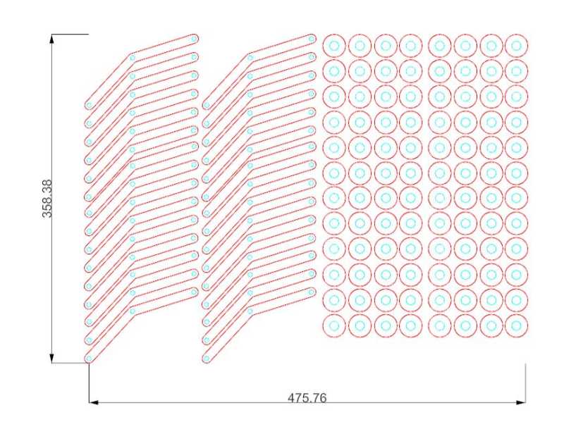
My main focus for the day is to have something physical that looks like a final project. I started by cutting the final parts in acrylic. This time I used different thickness for each part, the structure is a pìece of 6mm and the structure is made with 5mm acrylic Here are the archive before the laser cut
I put everything to cut and then I start to mount it
I also have the 3dparts from yesterday ready to be use.
.jpg)
Here is my solution for the stepper and the board, I don't wan to hide it because I feel that electronic are something that deserves to be seen and since this is a sculpture object and not something that it's going to be touch i can take the risk to leave everything outside.
.jpg)
I mounted the structure of acrylic with the 3d parts.
.jpg)
Also, I figured out a solution for the copper rods and the 3d elements.
.jpg)
Now, at the end of the day I want to test the stepmotor with the hole structure and see what happens.
This happens. First it's not working with the final board because the final board it's not working. Second, the preboard that I mave work odd with thi sstepper and here is the confirmation. The only curious thing it's that the step motor it's in someway "intelligent" because it change the directions when it finds any opposition. My classmate Rodrigo think that it is a great discovery because it's a machina that can't couse any harm. Well, I feel harmed. After some tries with different amperes and voltages I decided to left this thing for tomorrow. I'm going to buy a new stepper first thing in the morning and see if it's only the motor or everything it's against me.
Tomorrow it's Monday, the presentation it's on wednesday so tomorrow it's my last chance to make this board work with one step motor If I want to have something in front of Neil
NEOPIXEL
Before I went home I tried the Neopixel with the Helioduino, I sold some of them to three wires and test them turnning them on or off with arduino. They work fine, all of them. another reason to be worried about my drivers.
Conclusions of the day.
Tomorrow it's going to be a bad day. Many thing to do. At least the structure it's good. Let's see what happens with the stepper tomorrow.
09/06/2019. Debugging
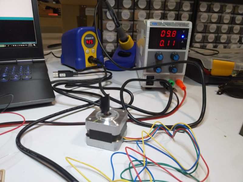
I bought a new step motor, a Nema 17 of 0.3amps and I was really excited to see if it works. With the first mini driver boards everythign was fine, so at least the problem here was in the other motor and not in the board. Now I tried again in the Helioduino board... Nothing... but finally...
At the end I've found my stupid, stupid error, I had a wrong connection in my drives the LSS pin had to be connected to the ground, mine wasn't connected at all. I fixed that and connect the ground from both faves. It's curius but Eagle doesn't advise of this problem. Well, Let see if I've found the problem.
It's alive! it's a frankestain but it's alive. Anyway it's the stepmotors in the analog pin the one who is moving correctly, the other one it's having the same problem than the 2.5V step motor with the old board... Interesting. I asked Marta and she was very surprised, but she didn't know the answer, anyway, I hae a stepper moving. at last!
Programmign comunications and reactions
After this good moment with the stepmotor I focused on the programming of my two boards and they interact between them. here is a video of my first test using the phototransistor to change the speed of the step motor. It's important to use a Map value to adapt the values from the phototransistor (from 0 to 1024) to the ones described in the stepper.h library.
)
Conclusions of the day.
Well it looks like thing are fnding their space and my head it's working better. Undestand the programation it has create a vere particular spanish guy, me.
11/06/2019. The day before. Now or never..
Today it's the day to do eveything. Let's think for a moment; I have the different parts, now it's the time to mix the whole thing to create something unite and then make it work, record a video, create a slide... it's going to be a long day.
Solding the rods
.jpg)
Since I decided to don't use wires I have to measure, cut and sold all the copper rods that connect the sensor and the Neo pixel with the central board. The result it's beautiful and it works
.jpg)
.jpg)
.jpg)
Now I have to sold the Neo pixel and checked if they worked.
They worked so I can go to the next step.
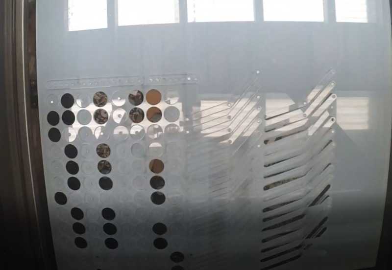
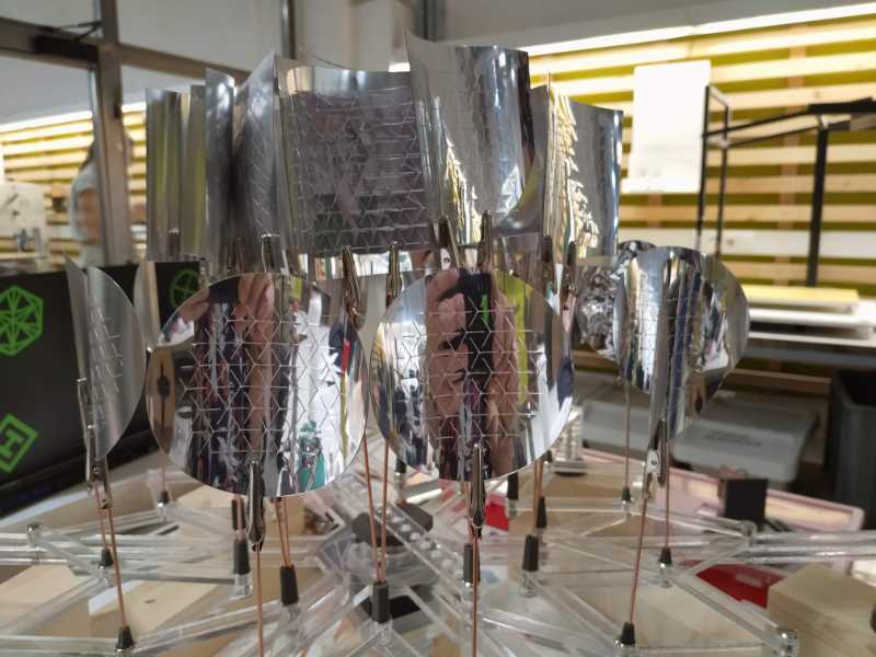
Vynil cuttting the PVC
.jpg)
.jpg)
The vynil gave some problems: the material it's too thick and hard for the machine, it can be cut but i lost many parts because the knife get stuck usually. At some point I dicided to cut only the exterior of the mirrors to save some time, now I have half of the mirrors with the origami pattern and half without it. It's ok because it looks cool anyway and rest some noise the whole object.
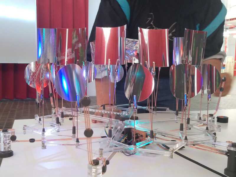
Construction
The rest of the day wasn't to think, it was a day to work hard and prepare all the connections, wires, rods that need to be in the structure, very long day. I think this video resumes it better than any word. 12 long hours without stop.
The end of the day
The final project it's almost done, I'm having some issues with the Neopixel and the current supply but I can't think a lot about it. I have this night to prepare my video and my slider, tomorrow we will see if I can improve what I have now.
12/06/2019. Presentation day
Day D. I don't have sleep a lot but my slider and my video are ready, I'm only worried about the problems that I detected yesterday in the evening like the power supply and the neopixel. At some point I discover that I connected all of them wrong and that's why they are nos working. So I have to sold them again. Here is the result of in sort videos.
Here I'm testing the neopixel and they looked good!
here it's the last test of the mechanism before the final presentation... ups i'm loosing a screw!
PRESENTATION
The project it's ready and quiet, it's time to wait for my turn and see what happens when Neil watch my proyect.
Proyect Develpment checklist
What task have been completed, and what tasks remain?
The whole project is finished but I would like to do some improvements, I couldn't sold and test the sensor board with the RGB sensor, I only used one motor and the helioduino is desing for two.
After the presentation I started with the improvements and I would put everything here when I finished
What has worked? What hasn't?
The mechanism and the copper rods worked and all the components work well.
But, one of the only the drivers and connections for one motor are working fine and the board needs to be millit again with some modifications. I want to add the second movement and the RGB sensor and make them work.
What questions need to be resolved?
The mechanism is not as fluid as I would like to, and it almost get stuck in some points. why?
The bib (2.5A) step motor moved very strange but the result was interesting. A harmless motor, I would like to make some research about this.
What will happen when?
don't know, I need to do research
What have you learned?
A few things about motors and electronics, many about order and planification. I could finished on time but I have to work very hard and I'm sure that it was not good for my health.
I would like to say as conclusion -and this can sound mainstream but it's true- that what I learned it's that I have many things to learn. The main reason to do the Fabacademy was to lost my fear to programming and electronics, and this goal it's complete now there is a long path to improve this project and create new ones.
Future plans and wishes
I think that the phototransistor is enough to pass the final project assignment But I still want to do some changes to my final project.first I would like to improve the sensor with the RGB one.
Sensor boards (to be)
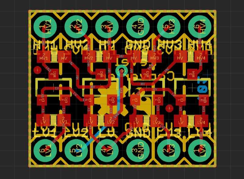
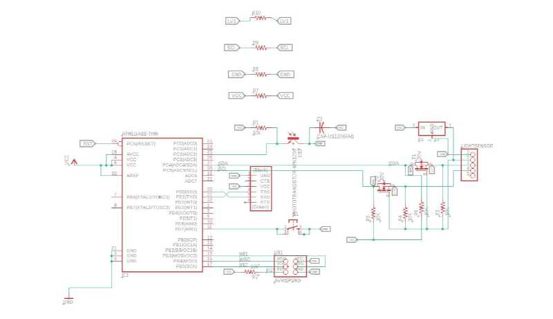
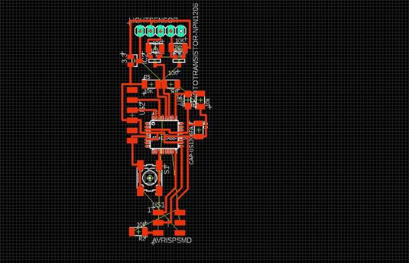
I designed a more complex version based on the 168 but I did not have enough time to fabricate and test this board and I really excited to know if my "home made" logical conversor works.
I have ready the board but now I have to test it.
Improving Helioduino
After all the wires that I had to use to fix the Helioduino I want to mill a new board with all that connections fixed. Also, I think it's a good opportunity to add some extras, more and better connectiosn for Neopixels and a pfemale power supply connector to avoid wire in this and have a cleaner output.
I need to buy more copper sheets because we finished them for the final project. But as you can see the board is ready to be milled. I think this one looks like more ordered, altought the old one was more compact.